Page 356 of 1202
H00234
D squibP squibAirbag Sensor
Assembly
Spiral
Cable LOCK
AB0117
N12639
H00026
Airbag Sensor Assembly LOCK
- DIAGNOSTICSSUPPLEMENTAL RESTRAINT SYSTEM
DI-181
1996 TERCEL (RM440U)
INSPECTION PROCEDURE
1 Preparation.
PREPARATION:
(a) Disconnect negative (-) terminal cable from the battery,
and wait at least 90 seconds.
(b) Remove steering wheel pad (See page SR-13).
(c) Disconnect connector of front passenger airbag assem-
bly (See page RS-21).
CAUTION:
Store the steering wheel pad with the front surface facing
upward.
2 Does SRS warning light turn off?
PREPARATION:
(a) Disconnect airbag sensor assembly connector.
(b) Connect negative (-) terminal cable to battery.
CHECK:
Check operation of SRS warning light.
NO Check SRS warning light circuit or terminal AB
circuit of DLC1.
YES
Replace airbag sensor assembly.
Page 363 of 1202

AB0117 AB0118 AB0119
R12658H00032
LOCK
ACC
ON
or
Airbag Sensor Assembly
Tc
DI-188
- DIAGNOSTICSSUPPLEMENTAL RESTRAINT SYSTEM
1996 TERCEL (RM440U)
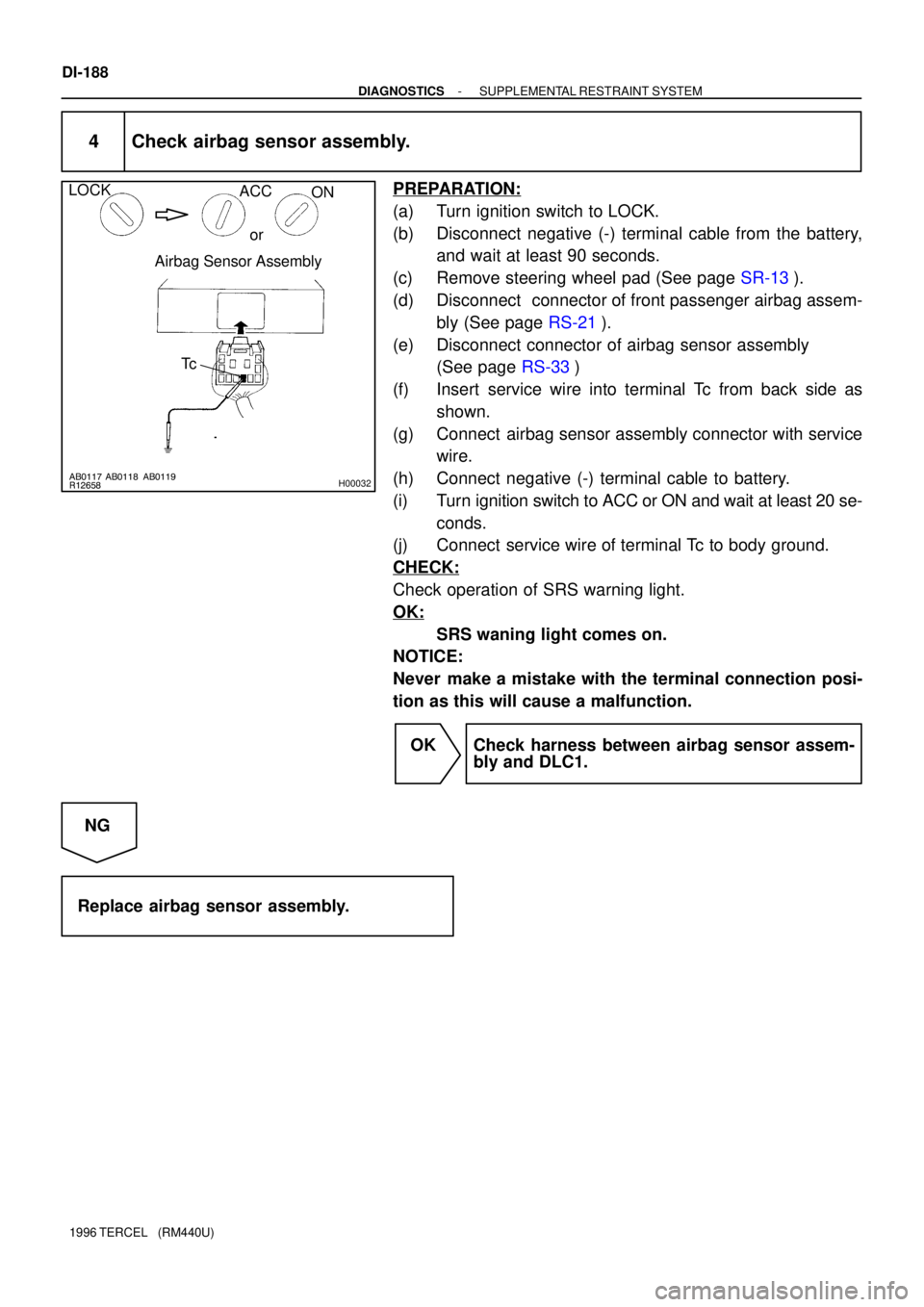
4 Check airbag sensor assembly.
PREPARATION:
(a) Turn ignition switch to LOCK.
(b) Disconnect negative (-) terminal cable from the battery,
and wait at least 90 seconds.
(c) Remove steering wheel pad (See page SR-13).
(d) Disconnect connector of front passenger airbag assem-
bly (See page RS-21).
(e) Disconnect connector of airbag sensor assembly
(See page RS-33)
(f) Insert service wire into terminal Tc from back side as
shown.
(g) Connect airbag sensor assembly connector with service
wire.
(h) Connect negative (-) terminal cable to battery.
(i) Turn ignition switch to ACC or ON and wait at least 20 se-
conds.
(j) Connect service wire of terminal Tc to body ground.
CHECK:
Check operation of SRS warning light.
OK:
SRS waning light comes on.
NOTICE:
Never make a mistake with the terminal connection posi-
tion as this will cause a malfunction.
OK Check harness between airbag sensor assem-
bly and DLC1.
NG
Replace airbag sensor assembly.
Page 492 of 1202
EM0JQ-06
EM9411
EM9412
P20480
SST
P20478
SST
P20477
12 mm
Hexagon
Wrench EM-70
- ENGINE MECHANICALCYLINDER BLOCK
1996 TERCEL (RM440U)
DISASSEMBLY
1. M/T:
REMOVE CLUTCH COVER AND DISC
2. REMOVE FLYWHEEL (M/T) OR DRIVE PLATE (A/T)
3. REMOVE REAR END PLATE
4. INSTALL ENGINE TO ENGINE STAND FOR DIS-
ASSEMBLY
5. REMOVE TIMING BELT AND PULLEYS
6. REMOVE CYLINDER HEAD
7. REMOVE OIL DIPSTICK GUIDE AND GENERATOR
ADJUSTING BAR
8. REMOVE WATER PUMP WITH WATER INLET PIPE
9. REMOVE GENERATOR BRACKET
10. REMOVE KNOCK SENSOR
Using SST, remove the knock sensor.
SST 09816-30010
11. REMOVE RH ENGINE MOUNTING BRACKET
12. REMOVE OIL FILTER
13. REMOVE OIL PRESSURE SWITCH
Using SST, remove the oil pressure switch.
SST 09816-30010
14. REMOVE OIL PUMP AND PRESSURE REGULATOR
VA LV E
15. REMOVE OIL FILTER UNION
Using a 12 mm hexagon wrench, remove the oil filter union.
Page 512 of 1202
P20750
P20480
SST
P20545
EM9412
EM7333
EM-90
- ENGINE MECHANICALCYLINDER BLOCK
1996 TERCEL (RM440U)
15. INSTALL RH ENGINE MOUNTING BRACKET
Torque: 58 N´m (590 kgf´cm, 43 ft´lbf)
16. INSTALL KNOCK SENSOR
Using SST, install the knock sensor.
SST 09816-30010
Torque: 45 N´m (450 kgf´cm, 33 ft´lbf)
17. INSTALL GENERATOR BRACKET
Torque: 24 N´m (240 kgf´cm, 18 ft´lbf)
18. INSTALL WATER PUMP WITH WATER INLET PIPE
19. INSTALL OIL DIPSTICK GUIDE AND GENERATOR AD-
JUSTING BAR
20. INSTALL CYLINDER HEAD
21. INSTALL TIMING BELT AND PULLEYS
22. REMOVE ENGINE STAND
23. INSTALL REAR END PLATE
Torque: 10 N´m (100 kgf´cm, 7 ft´lbf)
24. M/T:
INSTALL FLYWHEEL
(a) Apply adhesive to 2 or 3 threads of new mounting bolt
end.
Adhesive:
Part No. 08833-00070, THREE BOND 1324 or
equivalent
Page 513 of 1202
EM9410
1
2 3
45
6
- ENGINE MECHANICALCYLINDER BLOCK
EM-91
1996 TERCEL (RM440U)
(b) Install the flywheel on the crankshaft.
(c) Install and uniformly tighten the mounting bolts, in several
passes, in the sequence shown.
Torque: 90 N´m (900 kgf´cm, 65 ft´lbf)
25. A/T:
INSTALL DRIVE PLATE (See step 24)
26. M/T:
INSTALL CLUTCH DISC AND COVER
Page 667 of 1202

ST0661
Free
Lock
ST0667
P25604
Terminal C
Continuity Terminal 50
P25605
Continuity Terminal 50 Switch
Body
- STARTINGSTARTER (Planetary Type)
ST-21
1996 TERCEL (RM440U)
6. INSPECT CLUTCH AND GEAR
(a) Check the gear teeth on the planetary gear, internal gear
and starter clutch for wear or damage.
If the gear is damaged, replace it.
If the starter clutch teeth are damaged, replace the starter
clutch and also inspect the flywheel ring gear for wear or dam-
age.
(b) Check the starter clutch.
Rotate the clutch pinion gear clockwise and check that it
turns freely. Try to rotate the clutch pinion gear counter-
clockwise and check that it locks.
If necessary, replace the starter clutch.
7. INSPECT MAGNETIC SWITCH
(a) Check the plunger.
Push in the plunger and replace it. Check that it returns
quickly to its original position.
If necessary, replace the magnetic switch.
(b) Check the pull-in coil for open circuit.
Using an ohmmeter, check that there is continuity be-
tween terminals 50 and C.
If there is no continuity, replace the magnetic switch.
(c) Check the hold-in coil for open circuit.
Using an ohmmeter, check that there is continuity be-
tween terminal 50 and the switch body.
If there is no continuity, replace the magnetic switch.
Page 697 of 1202

CL05O-03
- CLUTCHTROUBLESHOOTING
CL-1
696 Author�: Date�:
1996 TERCEL (RM440U)
TROUBLESHOOTING
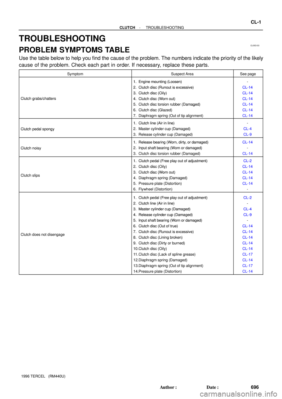
PROBLEM SYMPTOMS TABLE
Use the table below to help you find the cause of the problem. The numbers indicate the priority of the likely
cause of the problem. Check each part in order. If necessary, replace these parts.
SymptomSuspect AreaSee page
1. Engine mounting (Loosen)-1.Engine mounting (Loosen)
2. Clutch disc (Runout is excessive)
-
CL-14
2.Clutch disc (Runout is excessive)
3. Clutch disc (Oily)
CL-14
CL-14
Clutch grabs/chatters
3.Clutch disc (Oily)
4. Clutch disc (Worn out)
CL-14
CL-14Clutch grabs/chatters4.Clutch disc (Worn out)
5. Clutch disc torsion rubber (Damaged)
CL-14
CL-145.Clutch disc torsion rubber (Damaged)
6. Clutch disc (Glazed)
CL 14
CL-146.Clutch disc (Glazed)
7. Diaphragm spring (Out of tip alignment)
CL 14
CL-14
1. Clutch line (Air in line)-
Clutch pedal spongy
1.Clutch line (Air in line)
2. Master cylinder cup (Damaged)
-
CL-4
Clutch edal s ongy2.Master cylinder cu (Damaged)
3. Release cylinder cup (Damaged)
CL 4
CL-9
1. Release bearing (Worn, dirty, or damaged)CL-14
Clutch noisy
1.Release bearing (Worn, dirty, or damaged)
2. Input shaft bearing (Worn or damaged)
CL-14
-Clutch noisy2.In ut shaft bearing (Worn or damaged)
3. Clutch disc torsion rubber (Damaged)CL-14
1. Clutch pedal (Free play out of adjustment)CL-21.Clutch edal (Free lay out of adjustment)
2. Clutch disc (Oily)
CL-2
CL-14
Cl t h li
2.Clutch disc (Oily)
3. Clutch disc (Worn out)
CL-14
CL-14Clutch slips3.Clutch disc (Worn out)
4. Diaphragm spring (Damaged)
CL 14
CL-144.Dia hragm s ring (Damaged)
5. Pressure plate (Distortion)
CL 14
CL-145. Pressure late (Distortion)
6. Flywheel (Distortion)
CL 14
-
1 Clutchpedal (Freeplay out of adjustment)CL-21.Clutch pedal (Free play out of adjustment)
2 Clutch line (Air in line)CL-2
-2.Clutch line (Air in line)
3 Master cylinder cu
p(Damaged)
-
CL-43.Master cylinder cup (Damaged)
4. Release cylinder cu
p(Damaged)
CL-4
CL
-94.Release cylinder cup (Damaged)
5
. Input shaft bearing (Worn or damaged)
CL-9
-5.In ut shaft bearing (Worn or damaged)
6. Clutch disc (Out of true)
-
CL-14
Cl t h d t di
6.Clutch disc (Out of true)
7. Clutch disc (Runout is excessive)
CL-14
CL-14Clutch does not disengage7.Clutch disc (Runout is excessive)
8. Clutch disc (Lining broken)
CL-14
CL-148.Clutch disc (Lining broken)
9. Clutch disc (Dirty or burned)
CL-14
CL-149.Clutch disc (Dirty or burned)
10.Clutch disc (Oily)
CL 14
CL-1410.Clutch disc (Oily)
11. Clutch disc (Lack of spline grease)
CL 14
CL-1711. Clutch disc (Lack of s line grease)
12.Diaphragm spring (Damaged)
CL 17
CL-14gg(g)
13.Diaphragm spring (Out of tip alignment)CL-17gg( g)
14.Pressure plate (Distortion)CL-14
Page 698 of 1202

CL0649
Push Rod Play and Freeplay Adjust Point
Pedal Height
Adjust Point
Push Rod Play
Pedal HeightCL05P-04
CL0102
Pedal Freeplay
CL0512
25 mm (0.98 in.) or More
Full Stroke
End PositionRelease Point
CL-2
- CLUTCHCLUTCH PEDAL
697 Author�: Date�:
1996 TERCEL (RM440U)
CLUTCH PEDAL
INSPECTION
1. CHECK THAT PEDAL HEIGHT IS CORRECT
Pedal height from dash panel:
143.0 - 151.0 mm (5.629 - 5.944 in.)
2. IF NECESSARY, ADJUST PEDAL HEIGHT
Loosen the lock nut and turn the stopper bolt until the height is
correct. Tighten the lock nut.
3. CHECK PEDAL FREEPLAY AND PUSH ROD PLAY
Push in on the pedal until the beginning of clutch resistance is
felt.
Pedal freeplay: 5.0 - 15.0 mm (0.196 - 0.591 in.)
Gently push on the pedal until the resistance begins to in-
crease.
Push rod play at pedal top:
1.0-5.0 mm (0.039-0.196 in.)
4. IF NECESSARY, ADJUST PEDAL FREEPLAY AND
PUSH ROD PLAY
(a) Loosen the lock nut and turn the push rod until the free-
play and push rod play are correct.
(b) Tighten the lock nut.
(c) After adjusting the pedal freeplay, check the pedal height.
(d) Connect the air duct and install the lower finish panel.
5. CHECK CLUTCH RELEASE POINT
(a) Pull the parking brake lever and install wheel stopper.
(b) Start and idle the engine.
(c) Without depressing the clutch pedal, slowly shift the shift
lever into reverse position until the gears contact.
(d) Gradually depress the clutch pedal and measure the
stroke distance from the point that the gear noise stops
(release point) up to the full stroke end position.
Standard distance:
25 mm (0.98 in.) or more
(From pedal stroke end position to release point)
If the distance is not as specified, perform the following opera-
tions.
�Inspect pedal height.
�Inspect push rod play and pedal freeplay.
�Bleed the clutch line.
�Inspect the clutch cover and disc.