Page 725 of 1354

S01805
S01793
9 10
3 45 6
1 2
7 8
EM7797
Seal Packing
S01649
S01645
− ENGINE MECHANICALCYLINDER HEAD
EM−59
1996 RAV4 (RM447U)
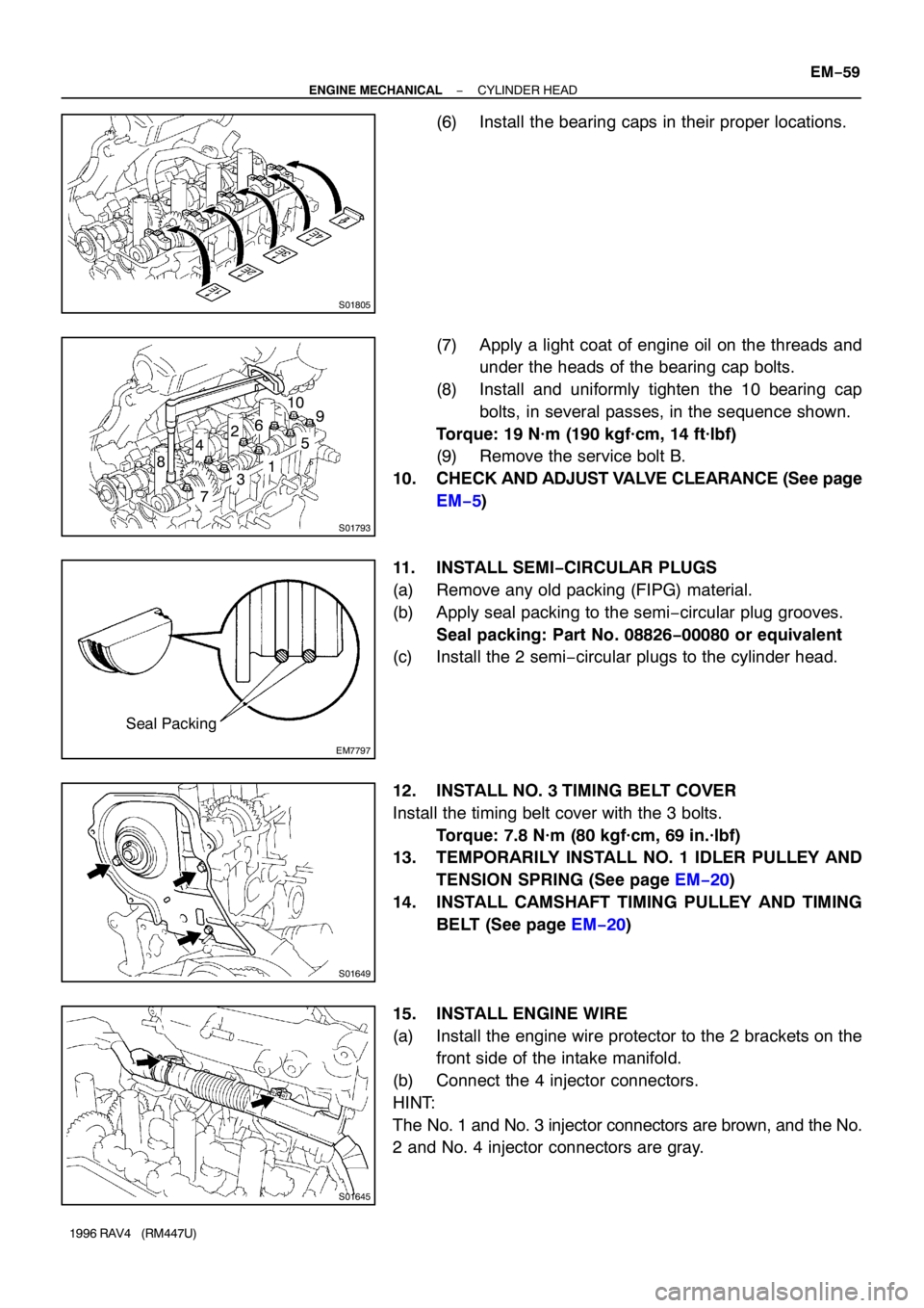
(6) Install the bearing caps in their proper locations.
(7) Apply a light coat of engine oil on the threads and
under the heads of the bearing cap bolts.
(8) Install and uniformly tighten the 10 bearing cap
bolts, in several passes, in the sequence shown.
Torque: 19 N·m (190 kgf·cm, 14 ft·lbf)
(9) Remove the service bolt B.
10. CHECK AND ADJUST VALVE CLEARANCE (See page
EM−5)
11. INSTALL SEMI−CIRCULAR PLUGS
(a) Remove any old packing (FIPG) material.
(b) Apply seal packing to the semi−circular plug grooves.
Seal packing: Part No. 08826−00080 or equivalent
(c) Install the 2 semi−circular plugs to the cylinder head.
12. INSTALL NO. 3 TIMING BELT COVER
Install the timing belt cover with the 3 bolts.
Torque: 7.8 N·m (80 kgf·cm, 69 in.·lbf)
13. TEMPORARILY INSTALL NO. 1 IDLER PULLEY AND
TENSION SPRING (See page EM−20)
14. INSTALL CAMSHAFT TIMING PULLEY AND TIMING
BELT (See page EM−20)
15. INSTALL ENGINE WIRE
(a) Install the engine wire protector to the 2 brackets on the
front side of the intake manifold.
(b) Connect the 4 injector connectors.
HINT:
The No. 1 and No. 3 injector connectors are brown, and the No.
2 and No. 4 injector connectors are gray.
Page 726 of 1354

S01647
S01432
P03283
: Seal Packing
S01658Marking 15°
15°
Z17351
12 EM−60
− ENGINE MECHANICALCYLINDER HEAD
1996 RAV4 (RM447U)
(c) Install the engine wire protector to the LH side of the in-
take manifold with the 2 bolts.
(d) Push in the engine wire through the cowl panel.
(e) Install the wire clamp to the bracket.
(f) Connect the 2 ECM connectors.
(g) Connect the 2 connectors to the connectors on the brack-
et.
(h) Connect the connector to the J/B No. 4.
(i) Install the RH floor carpet center cover.
(j) Install the RH cowl side trim.
(k) Install the RH scuff plate.
16. INST ALL CYLINDER HEAD COVER
(a) Remove any old packing (FIPG) material.
(b) Apply seal packing to the cylinder head as shown in the
illustration.
Seal packing: Part No. 08826−00080 or equivalent
(c) Install the gasket to the head cover.
(d) Install the head cover with the 4 grommets and nuts. Uni-
formly tighten the nuts in several passes.
Torque: 23 N·m (230 kgf·cm, 17 ft·lbf)
HINT:
Install the grommets so that their markings are as shown in the
illustration.
(e) Install the engine wire protector to the 2 mounting bolts of
the No. 2 timing belt cover in the sequence shown.
(f) Connect the 3 clamps to the No. 2 timing belt cover and
generator drive belt adjusting bar.
(g) Connect the crankshaft position sensor connector.
(h) w/ A/C:
Connect the A/C compressor connector.
Page 727 of 1354

S01791
S01644
S01806
− ENGINE MECHANICALCYLINDER HEAD
EM−61
1996 RAV4 (RM447U)
(i) Connect the PCV hose to the intake manifold.
(j) Install the accelerator cable bracket with the 2 bolts.
17. INSTALL VSV FOR EGR (See page SF−42)
18. CONNECT GROUND CABLE
Connect the ground cable to the intake manifold with the bolt.
19. CONNECT KNOCK SENSOR CONNECTOR
20. CONNECT PS IDLE−UP AIR HOSES TO AIR TUBE
21. A/T only:
CONNECT A/T THROTTLE CONTROL CABLE TO IN-
TAKE MANIFOLD
Connect the control cable to the clamp on the rear side of the
intake manifold.
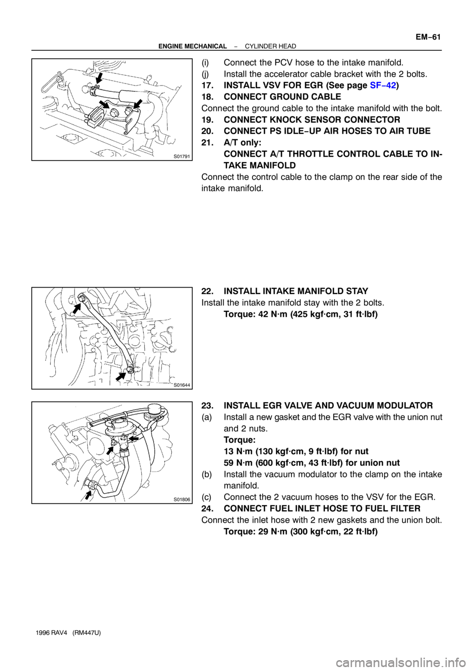
22. INSTALL INTAKE MANIFOLD STAY
Install the intake manifold stay with the 2 bolts.
Torque: 42 N·m (425 kgf·cm, 31 ft·lbf)
23. INSTALL EGR VALVE AND VACUUM MODULATOR
(a) Install a new gasket and the EGR valve with the union nut
and 2 nuts.
Torque:
13 N·m (130 kgf·cm, 9 ft·lbf) for nut
59 N·m (600 kgf·cm, 43 ft·lbf) for union nut
(b) Install the vacuum modulator to the clamp on the intake
manifold.
(c) Connect the 2 vacuum hoses to the VSV for the EGR.
24. CONNECT FUEL INLET HOSE TO FUEL FILTER
Connect the inlet hose with 2 new gaskets and the union bolt.
Torque: 29 N·m (300 kgf·cm, 22 ft·lbf)
Page 728 of 1354

S01560
(1)
(2)
(3)
P15451
ConnectNew
New
Gasket
O−Ring
S01594
S01368
EM−62
− ENGINE MECHANICALCYLINDER HEAD
1996 RAV4 (RM447U)
25. INSTALL HOSES AND GROUND STRAP
(a) Connect the vacuum sensor hose to the gas filter on the
intake manifold.
(b) Connect the brake booster vacuum hose to the intake
manifold.
(c) Connect the ground strap to the intake manifold.
26. INSTALL THROTTLE BODY (See page SF−33)
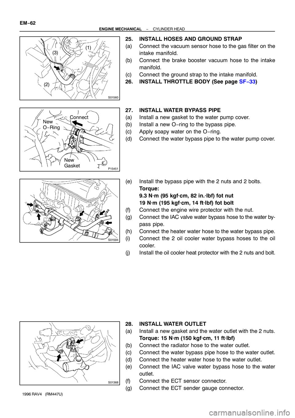
27. INSTALL WATER BYPASS PIPE
(a) Install a new gasket to the water pump cover.
(b) Install a new O−ring to the bypass pipe.
(c) Apply soapy water on the O−ring.
(d) Connect the water bypass pipe to the water pump cover.
(e) Install the bypass pipe with the 2 nuts and 2 bolts.
Torque:
9.3 N·m (95 kgf·cm, 82 in.·lbf) fot nut
19 N·m (195 kgf·cm, 14 ft·lbf) fot bolt
(f) Connect the engine wire protector with the nut.
(g) Connect the IAC valve water bypass hose to the water by-
pass pipe.
(h) Connect the heater water hose to the water bypass pipe.
(i) Connect the 2 oil cooler water bypass hoses to the oil
cooler.
(j) Install the oil cooler heat protector with the 2 nuts and bolt.
28. INSTALL WATER OUTLET
(a) Install a new gasket and the water outlet with the 2 nuts.
Torque: 15 N·m (150 kgf·cm, 11 ft·lbf)
(b) Connect the radiator hose to the water outlet.
(c) Connect the water bypass pipe hose to the water outlet.
(d) Connect the heater water hose to the water outlet.
(e) Connect the IAC valve water bypass hose to the water
outlet.
(f) Connect the ECT sensor connector.
(g) Connect the ECT sender gauge connector.
Page 729 of 1354

P03469
Retainer
Cushion
New Gasket
S01823
Oxygen Sensor
(Bank 1 Sensor 1)
Oxygen Sensor (Bank 1 Sensor 2)
S01557
− ENGINE MECHANICALCYLINDER HEAD
EM−63
1996 RAV4 (RM447U)
29. CONNECT OIL PRESSURE SWITCH CONNECTOR
30. ASSEMBLE EXHAUST MANIFOLD AND FRONT TWC
(a) Place the cushion, retainer and a new gasket on the
TWC.
(b) Install the TWC to the exhaust manifold with the 3 bolts
and 2 nuts.
Torque: 29 N·m (300 kgf·cm, 22 ft·lbf)
(c) Install the lower manifold heat insulator with the 5 bolts.
(d) Install the 2 TWC heat insulators with the 8 bolts.
31. INSTALL OXYGEN SENSOR (BANK 1 SENSOR 1) TO
EXHAUST MANIFOLD
Install a new gasket and the oxygen sensor with 2 new nuts.
Torque: 20 N·m (200 kgf·cm, 14 ft·lbf)
32. INSTALL OXYGEN SENSOR (BANK 1 SENSOR 2) TO
FRONT TWC
Torque: 44 N·m (450 kgf·cm, 33 ft·lbf)
33. INSTALL EXHAUST MANIFOLD AND FRONT TWC AS-
SEMBLY
(a) Install a new gasket, the exhaust manifold and TWC as-
sembly with the 6 nuts. Uniformly tighten the nuts in sev-
eral passes.
Torque: 49 N·m (500 kgf·cm, 36 ft·lbf)
(b) Install the RH exhaust manifold stay with the 2 bolts and
2 new nuts.
Torque: 42 N·m (452 kgf·cm, 31 ft·lbf)
(c) Install the upper manifold heat insulator with the 6 bolts.
(d) Connect the oxygen sensor (bank 1 sensor 1) connector.
(e) Connect the oxygen sensor (bank 1 sensor 2) connector.
34. INSTALL FRONT EXHAUST PIPE (See page EM−74)
35. INSTALL GENERATOR (See page CH−19)
36. INSTALL AIR CLEANER CASE AND CAP
37. CONNECT ACCELERATOR CABLE TO THROTTLE
BODY AND CABLE BRACKET
38. A/T only:
CONNECT THROTTLE CABLE TO THROTTLE BODY
AND CABLE BRACKET
Page 730 of 1354
EM−64
− ENGINE MECHANICALCYLINDER HEAD
1996 RAV4 (RM447U)
39. FILL WITH ENGINE COOLANT
40. START ENGINE AND CHECK FOR LEAKS
41. RECHECK ENGINE COOLANT LEVEL AND OIL LEV-
EL
42. INSTALL RH ENGINE UNDER COVER
Page 731 of 1354
EM0EV−02
A04063
N·m (kgf·cm, ft·lbf) : Specified torque
� Non−reusable part
29 (300, 22)
Hold Down ClampHold Down Clamp
BatteryEngine Hood
Battery Tray
Lower Radiator
HosePS Pump
w/ BracketCharcoal Canister
Battery Tray
IAT Sensor ConnectorAir Cleaner Cap
� Gasket
� Gasket
Fuel Inlet Hose
Fuel Filter
Water Inlet
Upper Radiator
Hose
Heater Hose
PS Pump Drive Belt
Generator Drive
Belt
Accelerator Cable
Generator
Generator Drive Belt
Adjusting Bar
Air Filter
EVAP VSV Connector
Air Cleaner Case
Radiator
Reservoir
Relay Block No. 2
Upper Cover
Relay Block No. 2
Wire Harness
A/C Compressor
Type B Type A
Type B Type A
− ENGINE MECHANICALENGINE UNIT
EM−65
1996 RAV4 (RM447U)
ENGINE UNIT
COMPONENTS
Page 732 of 1354
EM−66
− ENGINE MECHANICALENGINE UNIT
1996 RAV4 (RM447U)