Page 213 of 1354
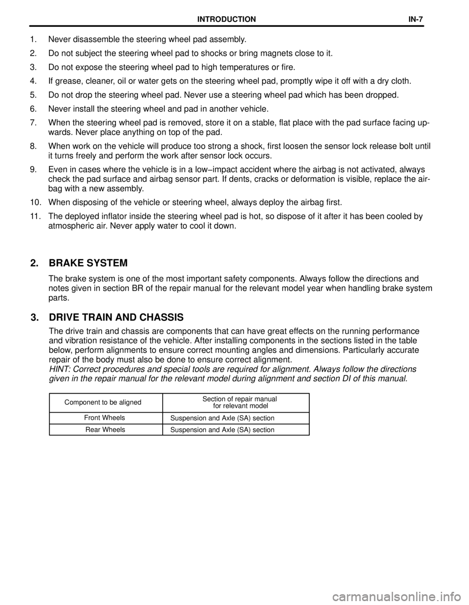
Component to be alignedSection of repair manual
for relevant model
Front Wheels
Suspension and Axle (SA) section
Rear Wheels
Suspension and Axle (SA) section
1. Never disassemble the steering wheel pad assembly.
2. Do not subject the steering wheel pad to shocks or bring magnets close to it.
3. Do not expose the steering wheel pad to high temperatures or fire.
4. If grease, cleaner, oil or water gets on the steering wheel pad, promptly wipe it off with a dry cloth.
5. Do not drop the steering wheel pad. Never use a steering wheel pad which has been dropped.
6. Never install the steering wheel and pad in another vehicle.
7. When the steering wheel pad is removed, store it on a stable, flat place with the pad surface facing upœ
wards. Never place anything on top of the pad.
8. When work on the vehicle will produce too strong a shock, first loosen the sensor lock release bolt until
it turns freely and perform the work after sensor lock occurs.
9. Even in cases where the vehicle is in a low-impact accident where the airbag is not activated, always
check the pad surface and airbag sensor part. If dents, cracks or deformation is visible, replace the airœ
bag with a new assembly.
10. When disposing of the vehicle or steering wheel, always deploy the airbag first.
11. The deployed inflator inside the steering wheel pad is hot, so dispose of it after it has been cooled by
atmospheric air. Never apply water to cool it down.
2. BRAKE SYSTEM
The brake system is one of the most important safety components. Always follow the directions and
notes given in section BR of the repair manual for the relevant model year when handling brake system
parts.
3. DRIVE TRAIN AND CHASSIS
The drive train and chassis are components that can have great effects on the running performance
and vibration resistance of the vehicle. After installing components in the sections listed in the table
below, perform alignments to ensure correct mounting angles and dimensions. Particularly accurate
repair of the body must also be done to ensure correct alignment.
HINT: Correct procedures and special tools are required for alignment. Always follow the directions
given in the repair manual for the relevant model during alignment and section DI of this manual.
INTRODUCTIONINœ7
Page 222 of 1354
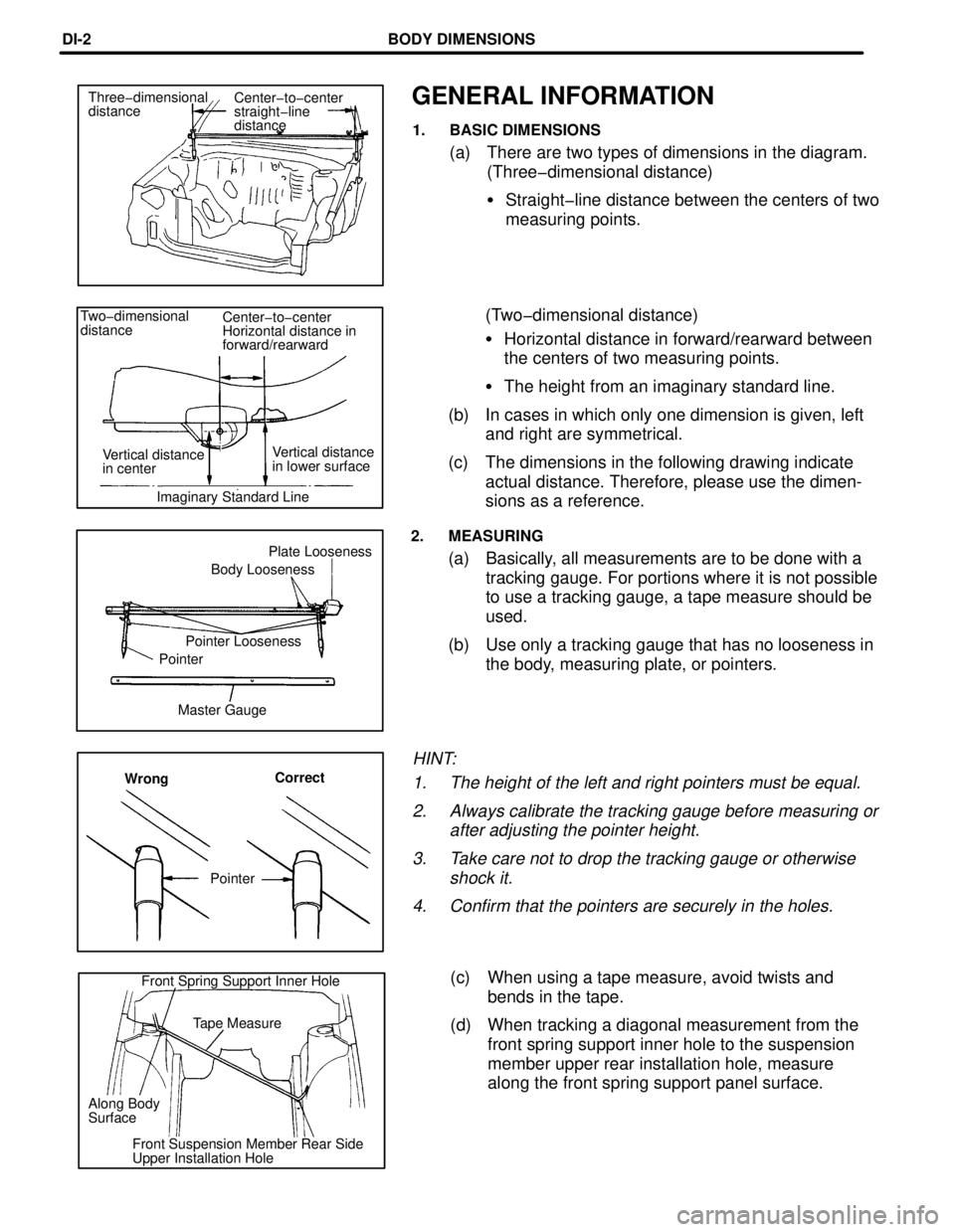
GENERAL INFORMATION
1. BASIC DIMENSIONS
(a) There are two types of dimensions in the diagram.
(Three-dimensional distance)
�Straight-line distance between the centers of two
measuring points.
(Two-dimensional distance)
�Horizontal distance in forward/rearward between
the centers of two measuring points.
�The height from an imaginary standard line.
(b) In cases in which only one dimension is given, left
and right are symmetrical.
(c) The dimensions in the following drawing indicate
actual distance. Therefore, please use the dimenœ
sions as a reference.
2. MEASURING
(a) Basically, all measurements are to be done with a
tracking gauge. For portions where it is not possible
to use a tracking gauge, a tape measure should be
used.
(b) Use only a tracking gauge that has no looseness in
the body, measuring plate, or pointers.
HINT:
1. The height of the left and right pointers must be equal.
2. Always calibrate the tracking gauge before measuring or
after adjusting the pointer height.
3. Take care not to drop the tracking gauge or otherwise
shock it.
4. Confirm that the pointers are securely in the holes.
(c) When using a tape measure, avoid twists and
bends in the tape.
(d) When tracking a diagonal measurement from the
front spring support inner hole to the suspension
member upper rear installation hole, measure
along the front spring support panel surface.
Center-to-center
straight-line
distance Three-dimensional
distance
Front Spring Support Inner Hole
Tape Measure
Along Body
Surface
Front Suspension Member Rear Side
Upper Installation HoleMaster Gauge PointerPointer LoosenessBody LoosenessPlate Looseness Two-dimensional
distanceCenter-to-center
Horizontal distance in
forward/rearward
Vertical distance
in lower surface Vertical distance
in center
Imaginary Standard Line
WrongCorrect
Pointer
BODY DIMENSIONSDIœ2
Page 223 of 1354
HINT: For symbols, capital letters indicate right side of vehicle,
small letters indicate left side of vehicle (Seen from rear).
K-k
1386
(54.57)552
(21.73)C-K
or
c-k
1494
(58.82)C-k
or
c-K
(Three-Dimensional Distance)
mm (in.)
Hole dia.
6 (0.24) nut
10 (0.39)
10 (0.39)
6 (0.24) nut
10 (0.39) Name
Cooler condenser installation nut
Radiator support extension standard hole
Radiator support standard hole
Front bumper support installation nut
Front apron to cowl side member standard hole Symbol
G, g
H, h
I, i
J
K, k Hole dia.
6 (0.24) nut
11 (0.43)
6 (0.24) nut
13 (0.51)
18 (0.71) Name
Front fender installation nut
Front spring support hole - inner
Front fender installation nut
Cowl top panel center mark
Front side member standard hole
Front side member standard hole Symbol
A, a
B, b
C, c
D, d
E, e
F, f
BODY DIMENSION DRAWINGS
ENGINE COMPARTMENT
BODY DIMENSIONSDIœ3
Page 224 of 1354
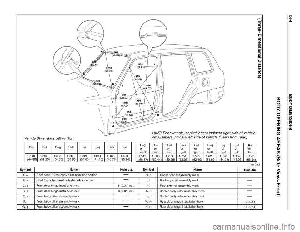
1,140
(44.88)E-e
1,302
(51.26)F-fVehicle Dimensions Left e Right
1,388
(54.65)G-g H-h
1,388
(54.65)I-i
1,388
(54.65)1,044
(41.10)J-j
1,188
(46.77)K-k
1,403
(55.24)L-l
1,541
(60.67)E-g
or
e-G
1,586
(62.44)E-i
or
e-IE-k
or
e-K
1,289
(50.75)1,754
(69.06)G-k
or
g-K
1,585
(62.40)G-l
or
g-LH-q
or
h-Q
1,628
(64.09)I-j
or
i-J
1,626
(64.02)J-r
or
j-R
1,169
(46.02)1,497
(58.94)
HINT: For symbols, capital letters indicate right side of vehicle,
small letters indicate left side of vehicle (Seen from rear.)
K-l
or
k-L
(Three-Dimensional Distance)
mm (in.)
Hole dia.
13 (0.51)
13 (0.51) Name
Rocker panel assembly mark
Rocker panel assembly mark
Roof side rail assembly mark
Center body pillar assembly mark
Center body pillar assembly mark
Rear door hinge installation hole
Rear door hinge installation hole Symbol
H, h
I, i
J, j
K, k
L, l
M, m
N, n Hole dia.
8 (0.31) nut
8 (0.31) nut Name
Roof panel / front body pillar adjoining portion
Cowl top outer panel outside radius corner
Front door hinge installation nut
Front door hinge installation nut
Front body pillar assembly mark
Front body pillar assembly mark
Front body pillar assembly mark Symbol
A, a
B, b
C, c
D, d
E, e
F, f
G, g
BODY OPENING AREAS (Side View-Front)
BODY DIMENSIONSDIœ4
Page 225 of 1354
Vehicle Dimensions Left e Right
O-o
1,188
(46.77)P-p
1,388
(54.66)1,388
(54.66)Q-q
R-r
1,049
(41.30)S-s
1,202
(47.32)1,404
(55.28)T-t
1,374
(54.09)O-s
or
o-SO-t
or
o-T
1,541
(60.67)1,463
(57.60)P-t
or
p-T
1,639
(64.53)Q-r
or
q-R
1,525
(60.04)S-t
or
s-T
HINT: For symbols, capital letters indicate right side of vehicle,
small letters indicate left side of vehicle (Seen from rear.)
mm (in.)
(Three-Dimensional Distance)
Hole dia. Name
Roof side rail assembly mark
Quarter panel assembly mark
Quarter panel assembly mark Symbol
R, r
S, s
T, t Hole dia. Name
Center body pillar assembly mark
Center body pillar assembly mark
Rocker panel assembly mark Symbol
O, o
P, p
Q, q
BODY OPENING AREAS (Side View-Rear)
BODY DIMENSIONSDIœ5
Page 226 of 1354
HINT: For symbols, capital letters indicate right side of vehicle,
small letters indicate left side of vehicle (Seen from rear).
mm (in.)
(Three-Dimensional Distance)
Hole dia.
6 (0.24) nut
7.5y7.5 (0.295y0.295)
16 (0.63) Name
Back door stopper installation nut-lower
Rear floor finish plate installation hole
Shock absorber installation hole
Roof side rail assembly mark Symbol
c
D, d
E, e
F, f Hole dia.
13 (0.51)
8 (0.31) nut
13 (0.51) Name
Back door opening frame / Roof panel adjoining
portion
Back door hinge installation hole-upper
B
Back door lock striker installation nut-upper
C
Back door hinge installation hole-lower Symbol
A, a
b
BODY OPENING AREAS (REAR View)
BODY DIMENSIONSDIœ6
Page 227 of 1354
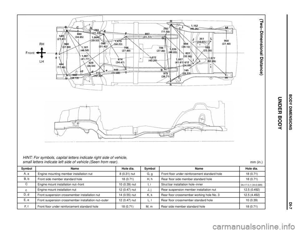
HINT: For symbols, capital letters indicate right side of vehicle,
small letters indicate left side of vehicle (Seen from rear).
(Two-Dimensional Distance)
mm (in.)
Hole dia.
18 (0.71)
18 (0.71)
34y17.5 (1.34y0.689)12.5 (0.492)
12.5 (4.492)
10 (0.39)
18 (0.71) Name
Front floor under reinforcement standard hole
Rear floor side member standard hole
Strut bar installation hole-inner
Rear suspension member installation nut
Rear floor crossmember working hole No. 3
Rear floor crossmember standard hole
Rear side member standard hole Symbol
G, g
H, h
I, i
J, j
K, k
L, l
M, m Hole dia.
8 (0.31) nut
18 (0.71)
10 (0.39) nut
12 (0.47) nut
14 (0.55) nut
12 (0.47) nut
18 (0.71) Name
Engine mounting member installation nut
Front side member standard hole
Engine mount installation nut-front
Engine mount installation nut
Front suspension crossmember installation nut
Front suspension crossmember installation nut-outer
Front floor under reinforcement standard hole Symbol
A, a
B, b
C
c
D, d
E, e
F, f
UNDER BODY
BODY DIMENSIONSDIœ7
Page 228 of 1354
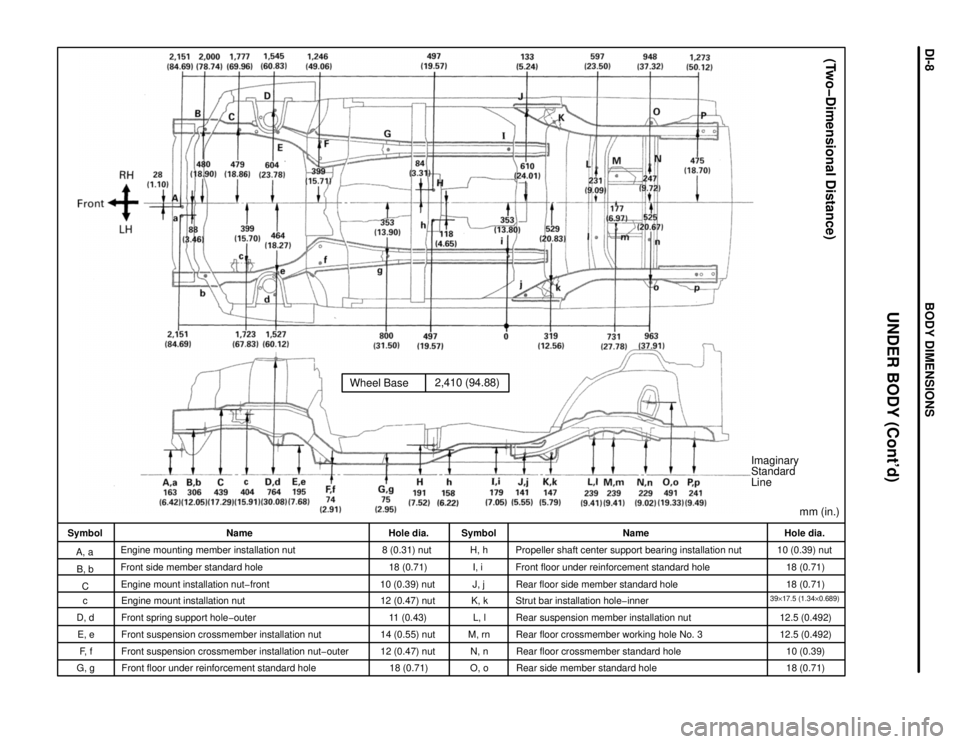
Wheel Base2,410 (94.88)
Imaginary
Standard
Line
mm (in.)
(Two-Dimensional Distance)
Hole dia.
10 (0.39) nut
18 (0.71)
18 (0.71)
39y17.5 (1.34y0.689)12.5 (0.492)
12.5 (0.492)
10 (0.39)
18 (0.71) Name
Propeller shaft center support bearing installation nut
Front floor under reinforcement standard hole
Rear floor side member standard hole
Strut bar installation hole-inner
Rear suspension member installation nut
Rear floor crossmember working hole No. 3
Rear floor crossmember standard hole
Rear side member standard hole Symbol
H, h
I, i
J, j
K, k
L, l
M, rn
N, n
O, o Hole dia.
8 (0.31) nut
18 (0.71)
10 (0.39) nut
12 (0.47) nut
11 (0.43)
14 (0.55) nut
12 (0.47) nut
18 (0.71) Name
Engine mounting member installation nut
Front side member standard hole
Engine mount installation nut-front
Engine mount installation nut
Front spring support hole-outer
Front suspension crossmember installation nut
Front suspension crossmember installation nut-outer
Front floor under reinforcement standard hole Symbol
A, a
B, b
C
c
D, d
E, e
F, f
UNDER BODY (Cont'd)
G, g
BODY DIMENSIONSDIœ8