Page 741 of 1354

S01559
Ground
Strap
Connector
R10966
S01283
B
SST
A
S01363
− ENGINE MECHANICALENGINE UNIT
EM−75
1996 RAV4 (RM447U)
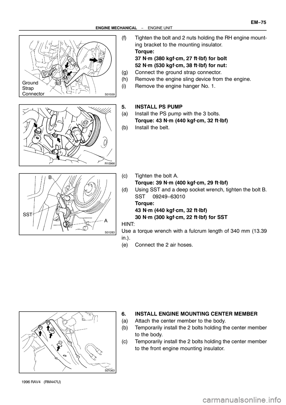
(f) Tighten the bolt and 2 nuts holding the RH engine mount-
ing bracket to the mounting insulator.
Torque:
37 N·m (380 kgf·cm, 27 ft·lbf) for bolt
52 N·m (530 kgf·cm, 38 ft·lbf) for nut:
(g) Connect the ground strap connector.
(h) Remove the engine sling device from the engine.
(i) Remove the engine hanger No. 1.
5. INSTALL PS PUMP
(a) Install the PS pump with the 3 bolts.
Torque: 43 N·m (440 kgf·cm, 32 ft·lbf)
(b) Install the belt.
(c) Tighten the bolt A.
Torque: 39 N·m (400 kgf·cm, 29 ft·lbf)
(d) Using SST and a deep socket wrench, tighten the bolt B.
SST 09249−63010
Torque:
43 N·m (440 kgf·cm, 32 ft·lbf)
30 N·m (300 kgf·cm, 22 ft·lbf) for SST
HINT:
Use a torque wrench with a fulcrum length of 340 mm (13.39
in.).
(e) Connect the 2 air hoses.
6. INSTALL ENGINE MOUNTING CENTER MEMBER
(a) Attach the center member to the body.
(b) Temporarily install the 2 bolts holding the center member
to the body.
(c) Temporarily install the 2 bolts holding the center member
to the front engine mounting insulator.
Page 742 of 1354

S01362
S01364
S01434
Z17304BB A EM−76
− ENGINE MECHANICALENGINE UNIT
1996 RAV4 (RM447U)
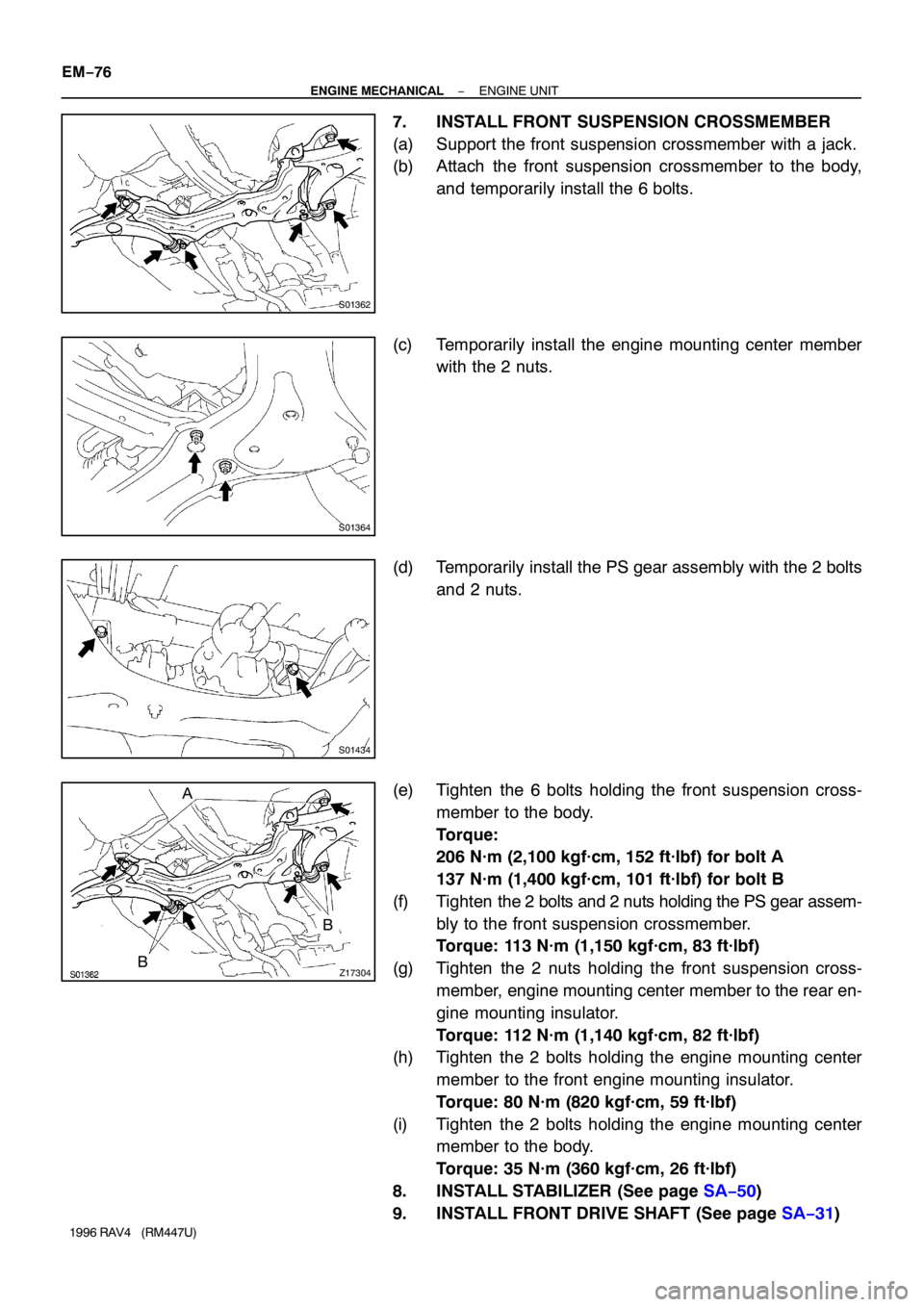
7. INSTALL FRONT SUSPENSION CROSSMEMBER
(a) Support the front suspension crossmember with a jack.
(b) Attach the front suspension crossmember to the body,
and temporarily install the 6 bolts.
(c) Temporarily install the engine mounting center member
with the 2 nuts.
(d) Temporarily install the PS gear assembly with the 2 bolts
and 2 nuts.
(e) Tighten the 6 bolts holding the front suspension cross-
member to the body.
Torque:
206 N·m (2,100 kgf·cm, 152 ft·lbf) for bolt A
137 N·m (1,400 kgf·cm, 101 ft·lbf) for bolt B
(f) Tighten the 2 bolts and 2 nuts holding the PS gear assem-
bly to the front suspension crossmember.
Torque: 113 N·m (1,150 kgf·cm, 83 ft·lbf)
(g) Tighten the 2 nuts holding the front suspension cross-
member, engine mounting center member to the rear en-
gine mounting insulator.
Torque: 112 N·m (1,140 kgf·cm, 82 ft·lbf)
(h) Tighten the 2 bolts holding the engine mounting center
member to the front engine mounting insulator.
Torque: 80 N·m (820 kgf·cm, 59 ft·lbf)
(i) Tighten the 2 bolts holding the engine mounting center
member to the body.
Torque: 35 N·m (360 kgf·cm, 26 ft·lbf)
8. INSTALL STABILIZER (See page SA−50)
9. INSTALL FRONT DRIVE SHAFT (See page SA−31)
Page 743 of 1354

S01347
S01285
S01432
− ENGINE MECHANICALENGINE UNIT
EM−77
1996 RAV4 (RM447U)
10. 4WD only:
INSTALL PROPELLER SHAFT (See page PR−9)
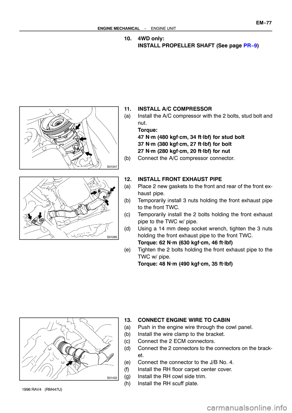
11. INSTALL A/C COMPRESSOR
(a) Install the A/C compressor with the 2 bolts, stud bolt and
nut.
Torque:
47 N·m (480 kgf·cm, 34 ft·lbf) for stud bolt
37 N·m (380 kgf·cm, 27 ft·lbf) for bolt
27 N·m (280 kgf·cm, 20 ft·lbf) for nut
(b) Connect the A/C compressor connector.
12. INSTALL FRONT EXHAUST PIPE
(a) Place 2 new gaskets to the front and rear of the front ex-
haust pipe.
(b) Temporarily install 3 nuts holding the front exhaust pipe
to the front TWC.
(c) Temporarily install the 2 bolts holding the front exhaust
pipe to the TWC w/ pipe.
(d) Using a 14 mm deep socket wrench, tighten the 3 nuts
holding the front exhaust pipe to the front TWC.
Torque: 62 N·m (630 kgf·cm, 46 ft·lbf)
(e) Tighten the 2 bolts holding the front exhaust pipe to the
TWC w/ pipe.
Torque: 48 N·m (490 kgf·cm, 35 ft·lbf)
13. CONNECT ENGINE WIRE TO CABIN
(a) Push in the engine wire through the cowl panel.
(b) Install the wire clamp to the bracket.
(c) Connect the 2 ECM connectors.
(d) Connect the 2 connectors to the connectors on the brack-
et.
(e) Connect the connector to the J/B No. 4.
(f) Install the RH floor carpet center cover.
(g) Install the RH cowl side trim.
(h) Install the RH scuff plate.
Page 744 of 1354

S01797
M/T
A/T
S01785
A/T Only
S01351
M/T Only
Back−up Light
Connector EM−78
− ENGINE MECHANICALENGINE UNIT
1996 RAV4 (RM447U)
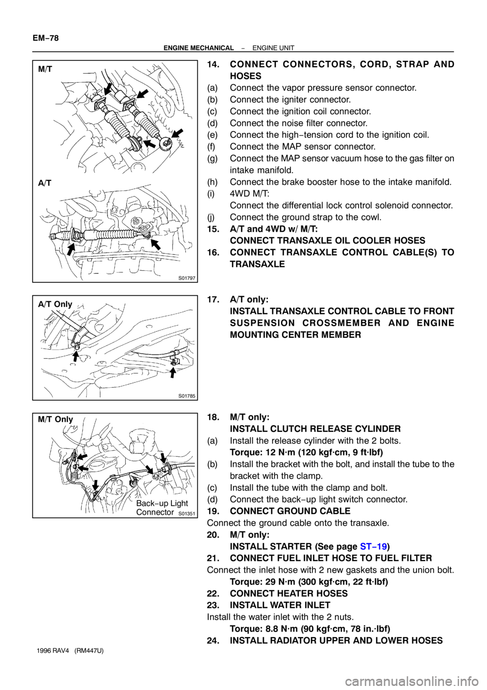
14. CONNECT CONNECTORS, CORD, STRAP AND
HOSES
(a) Connect the vapor pressure sensor connector.
(b) Connect the igniter connector.
(c) Connect the ignition coil connector.
(d) Connect the noise filter connector.
(e) Connect the high−tension cord to the ignition coil.
(f) Connect the MAP sensor connector.
(g) Connect the MAP sensor vacuum hose to the gas filter on
intake manifold.
(h) Connect the brake booster hose to the intake manifold.
(i) 4WD M/T:
Connect the differential lock control solenoid connector.
(j) Connect the ground strap to the cowl.
15. A/T and 4WD w/ M/T:
CONNECT TRANSAXLE OIL COOLER HOSES
16. CONNECT TRANSAXLE CONTROL CABLE(S) TO
TRANSAXLE
17. A/T only:
INSTALL TRANSAXLE CONTROL CABLE TO FRONT
SUSPENSION CROSSMEMBER AND ENGINE
MOUNTING CENTER MEMBER
18. M/T only:
INSTALL CLUTCH RELEASE CYLINDER
(a) Install the release cylinder with the 2 bolts.
Torque: 12 N·m (120 kgf·cm, 9 ft·lbf)
(b) Install the bracket with the bolt, and install the tube to the
bracket with the clamp.
(c) Install the tube with the clamp and bolt.
(d) Connect the back−up light switch connector.
19. CONNECT GROUND CABLE
Connect the ground cable onto the transaxle.
20. M/T only:
INSTALL STARTER (See page ST−19)
21. CONNECT FUEL INLET HOSE TO FUEL FILTER
Connect the inlet hose with 2 new gaskets and the union bolt.
Torque: 29 N·m (300 kgf·cm, 22 ft·lbf)
22. CONNECT HEATER HOSES
23. INSTALL WATER INLET
Install the water inlet with the 2 nuts.
Torque: 8.8 N·m (90 kgf·cm, 78 in.·lbf)
24. INSTALL RADIATOR UPPER AND LOWER HOSES
Page 745 of 1354
S01374
Cover
Connector
− ENGINE MECHANICALENGINE UNIT
EM−79
1996 RAV4 (RM447U)
25. INSTALL GENERATOR (See page CH−19)
26. INSTALL CHARCOAL CANISTER
27. CONNECT ENGINE WIRE TO RELAY BOX NO. 2
(a) Connect the engine wire to the relay block No.2 with the
2 nuts.
(b) Connect the connector.
(c) Install the upper cover.
(d) Connect the relay block No. 2 to the body with the 2 bolts.
28. INSTALL ACCELERATOR CABLE TO THROTTLE
BODY, CABLE BRACKET AND CLAMPS
29. INSTALL AIR CLEANER CASE AND CAP
30. INSTALL BATTERY
31. FILL WITH TRANSAXLE OIL
32. FILL WITH ENGINE OIL
33. FILL WITH ENGINE COOLANT
34. START ENGINE AND CHECK FOR LEAKS
35. PERFORM ENGINE ADJUSTMENT
36. CHECK FRONT WHEEL ALIGNMENT
37. INSTALL ENGINE UNDER COVERS
38. INSTALL ENGINE HOOD
39. ROAD TEST VEHICLE
Check for abnormal noises, shock slippage, correct shift points
and smooth operation.
40. RECHECK ENGINE COOLANT AND OIL LEVELS
Page 746 of 1354
EM0EY−03
See page EM−99
EM−80
− ENGINE MECHANICALCYLINDER BLOCK
1996 RAV4 (RM447U)
CYLINDER BLOCK
COMPONENTS
Page 747 of 1354
P15297
M/T
EM1BB−02
P15299
A/T
P13432
P15304
RH Engine
Mounting
Bracket
PS Pump
Bracket
S01580
1
3
2
− ENGINE MECHANICALCYLINDER BLOCK
EM−81
1996 RAV4 (RM447U)
DISASSEMBLY
1. M/T:
REMOVE FLYWHEEL
Remove the 8 bolts and flywheel.
2. A/T:
REMOVE DRIVE PLATE
Remove the 8 bolts, front plate, drive plate and rear spacer.
3. REMOVE REAR END PLATE
Remove the bolt and end plate.
4. INSTALL ENGINE TO ENGINE STAND FOR DIS-
ASSEMBLY
5. REMOVE RH ENGINE MOUNTING BRACKET
Remove the 3 bolts and mounting bracket.
6. REMOVE PS PUMP BRACKET
Remove the 3 bolts and PS pump bracket.
7. REMOVE TIMING BELT AND PULLEYS (See page
EM−15)
8. REMOVE CYLINDER HEAD (See page EM−33)
9. REMOVE OIL PAN AND OIL PUMP (See page LU−7)
10. REMOVE GENERATOR DRIVE BELT ADJUSTING
BAR, WATER PUMP AND WATER PUMP COVER AS-
SEMBLY
(a) Remove the bolt and adjusting bar.
(b) Remove the 3 bolts in the sequence shown, remove the
water pump, water pump cover assembly and O−ring.
11. REMOVE OIL COOLER (See page LU−18)
Page 748 of 1354
S01631
SST
P05527
P13434
P13435
P13436
EM−82
− ENGINE MECHANICALCYLINDER BLOCK
1996 RAV4 (RM447U)
12. REMOVE KNOCK SENSOR
Using SST, remove the knock sensor.
SST 09816−30010
13. REMOVE REAR OIL SEAL RETAINER
Remove the 6 bolts, retainer and gasket.
14. CHECK CONNECTING ROD THRUST CLEARANCE
Using a dial indicator, measure the thrust clearance while mov-
ing the connecting rod back and forth.
Standard thrust clearance:
0.160 − 0.312 mm (0.0063 − 0.0123 in.)
Maximum thrust clearance: 0.35 mm (0.0138 in.)
If the thrust clearance is greater than maximum, replace the
connecting rod assembly. If necessary, replace the crankshaft.
15. REMOVE CONNECTING ROD CAPS AND CHECK OIL
CLEARANCE
(a) Check the matchmarks on the connecting rod and cap to
ensure correct reassembly.
(b) Remove the 2 connecting rod cap nuts.