Page 765 of 1354
EM1BD−02
S01247
Front Mark
(Cavity)
Front Mark
(Protrusion)
Z17148
Code Mark
No. 1
No. 2Code Mark
S01227
Upper Side Rail
Expander
No. 2
Compression
RingLower Side
Rail No. 1 Compression
Ring
Front Mark
(Cavity)
P00797
− ENGINE MECHANICALCYLINDER BLOCK
EM−99
1996 RAV4 (RM447U)
REASSEMBLY
HINT:
�Thoroughly clean all parts to be assembled.
�Before installing the parts, apply new engine oil to all slid-
ing and rotating surfaces.
�Replace all gaskets, O−rings and oil seals with new parts.
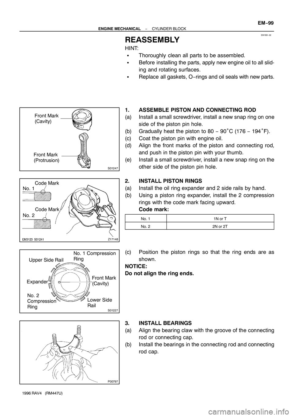
1. ASSEMBLE PISTON AND CONNECTING ROD
(a) Install a small screwdriver, install a new snap ring on one
side of the piston pin hole.
(b) Gradually heat the piston to 80 − 90°C (176 − 194°F).
(c) Coat the piston pin with engine oil.
(d) Align the front marks of the piston and connecting rod,
and push in the piston pin with your thumb.
(e) Install a small screwdriver, install a new snap ring on the
other side of the piston pin hole.
2. INSTALL PISTON RINGS
(a) Install the oil ring expander and 2 side rails by hand.
(b) Using a piston ring expander, install the 2 compression
rings with the code mark facing upward.
Code mark:
No. 11N or T
No. 22N or 2T
(c) Position the piston rings so that the ring ends are as
shown.
NOTICE:
Do not align the ring ends.
3. INSTALL BEARINGS
(a) Align the bearing claw with the groove of the connecting
rod or connecting cap.
(b) Install the bearings in the connecting rod and connecting
rod cap.
Page 766 of 1354
P05533
No.3 Others
22.9 mm19.2 mm
P05353
P03177
Mark
1, 2, 3, 4 or 5
P05354
P03173
EM−100
− ENGINE MECHANICALCYLINDER BLOCK
1996 RAV4 (RM447U)
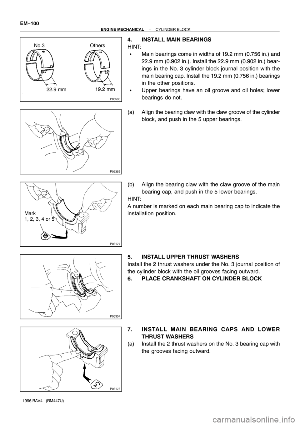
4. INSTALL MAIN BEARINGS
HINT:
�Main bearings come in widths of 19.2 mm (0.756 in.) and
22.9 mm (0.902 in.). Install the 22.9 mm (0.902 in.) bear-
ings in the No. 3 cylinder block journal position with the
main bearing cap. Install the 19.2 mm (0.756 in.) bearings
in the other positions.
�Upper bearings have an oil groove and oil holes; lower
bearings do not.
(a) Align the bearing claw with the claw groove of the cylinder
block, and push in the 5 upper bearings.
(b) Align the bearing claw with the claw groove of the main
bearing cap, and push in the 5 lower bearings.
HINT:
A number is marked on each main bearing cap to indicate the
installation position.
5. INSTALL UPPER THRUST WASHERS
Install the 2 thrust washers under the No. 3 journal position of
the cylinder block with the oil grooves facing outward.
6. PLACE CRANKSHAFT ON CYLINDER BLOCK
7. INSTALL MAIN BEARING CAPS AND LOWER
THRUST WASHERS
(a) Install the 2 thrust washers on the No. 3 bearing cap with
the grooves facing outward.
Page 767 of 1354
P13450
P13448
Z17147
Front Mark
(Cavity)
FrontPush
P13451
Front Mark
(Protrusion)
P13441
− ENGINE MECHANICALCYLINDER BLOCK
EM−101
1996 RAV4 (RM447U)
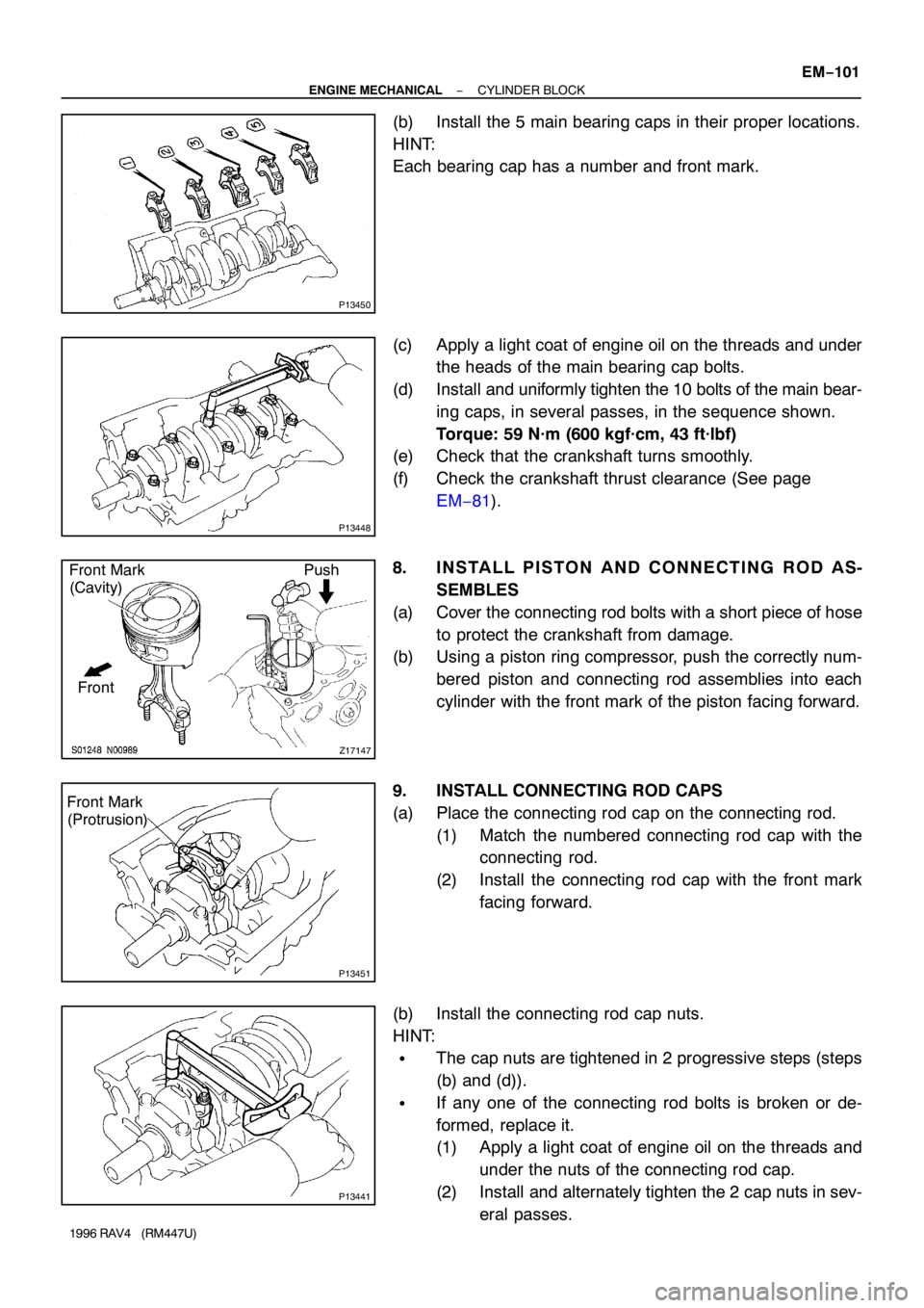
(b) Install the 5 main bearing caps in their proper locations.
HINT:
Each bearing cap has a number and front mark.
(c) Apply a light coat of engine oil on the threads and under
the heads of the main bearing cap bolts.
(d) Install and uniformly tighten the 10 bolts of the main bear-
ing caps, in several passes, in the sequence shown.
Torque: 59 N·m (600 kgf·cm, 43 ft·lbf)
(e) Check that the crankshaft turns smoothly.
(f) Check the crankshaft thrust clearance (See page
EM−81).
8. INSTALL PISTON AND CONNECTING ROD AS-
SEMBLES
(a) Cover the connecting rod bolts with a short piece of hose
to protect the crankshaft from damage.
(b) Using a piston ring compressor, push the correctly num-
bered piston and connecting rod assemblies into each
cylinder with the front mark of the piston facing forward.
9. INSTALL CONNECTING ROD CAPS
(a) Place the connecting rod cap on the connecting rod.
(1) Match the numbered connecting rod cap with the
connecting rod.
(2) Install the connecting rod cap with the front mark
facing forward.
(b) Install the connecting rod cap nuts.
HINT:
�The cap nuts are tightened in 2 progressive steps (steps
(b) and (d)).
�If any one of the connecting rod bolts is broken or de-
formed, replace it.
(1) Apply a light coat of engine oil on the threads and
under the nuts of the connecting rod cap.
(2) Install and alternately tighten the 2 cap nuts in sev-
eral passes.
Page 768 of 1354
P13453
Painted Mark
90°90°
P05527
S01632
SST
P15371
New O−Ring EM−102
− ENGINE MECHANICALCYLINDER BLOCK
1996 RAV4 (RM447U)
Torque: 25 N·m (250 kgf·cm, 18 ft·lbf)
If any one of the cap nuts does not meet the torque specifica-
tion, replace the connecting rod bolt and cap nut as a set.
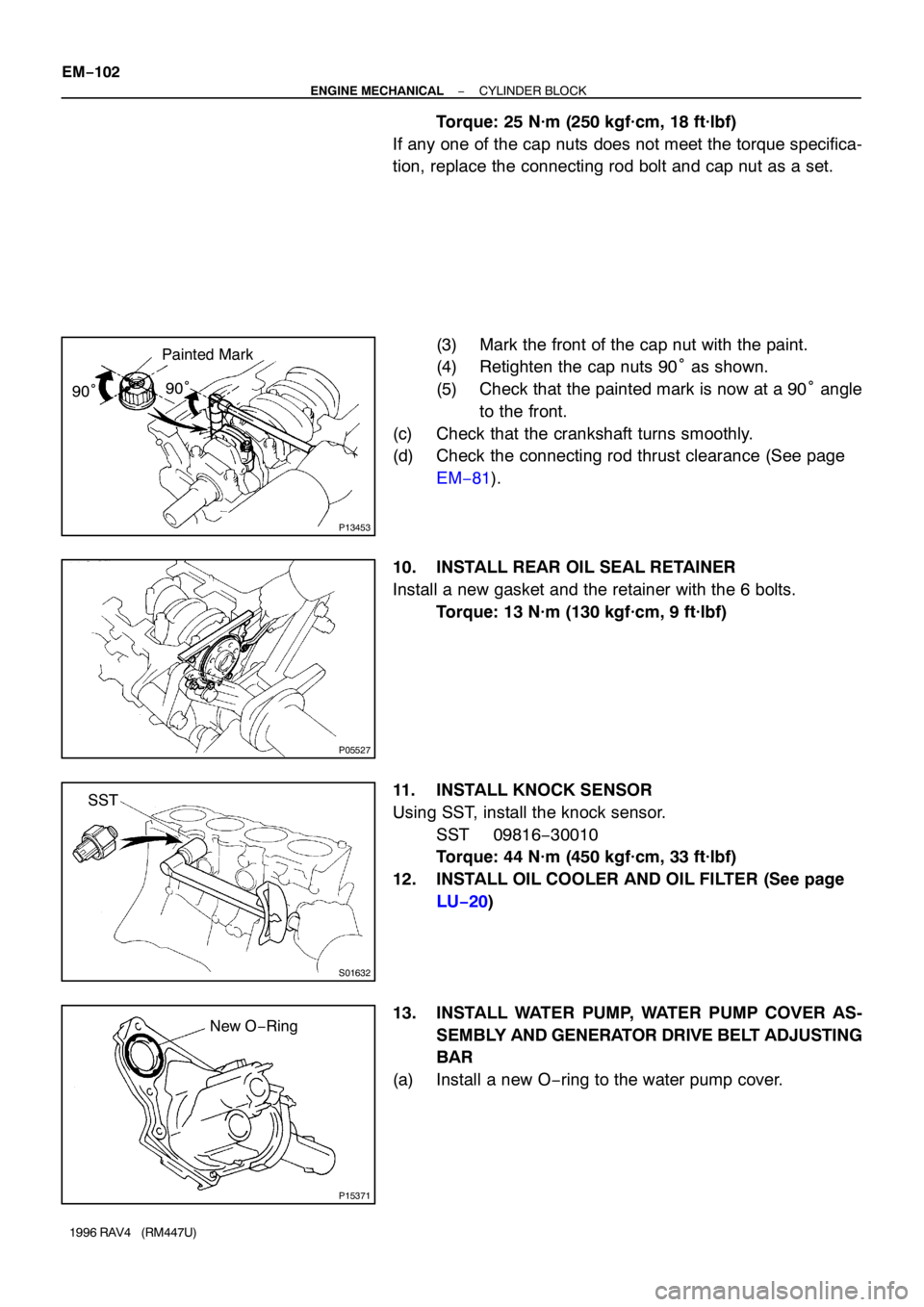
(3) Mark the front of the cap nut with the paint.
(4) Retighten the cap nuts 90° as shown.
(5) Check that the painted mark is now at a 90° angle
to the front.
(c) Check that the crankshaft turns smoothly.
(d) Check the connecting rod thrust clearance (See page
EM−81).
10. INSTALL REAR OIL SEAL RETAINER
Install a new gasket and the retainer with the 6 bolts.
Torque: 13 N·m (130 kgf·cm, 9 ft·lbf)
11. INSTALL KNOCK SENSOR
Using SST, install the knock sensor.
SST 09816−30010
Torque: 44 N·m (450 kgf·cm, 33 ft·lbf)
12. INSTALL OIL COOLER AND OIL FILTER (See page
LU−20)
13. INSTALL WATER PUMP, WATER PUMP COVER AS-
SEMBLY AND GENERATOR DRIVE BELT ADJUSTING
BAR
(a) Install a new O−ring to the water pump cover.
Page 769 of 1354
Z17349
3
1
2
P15304
RH Engine
Mounting
Bracket
PS Pump
Bracket
P13432
EM7333
P15298
3
1
2 M/T
5
8 7
6
4
− ENGINE MECHANICALCYLINDER BLOCK
EM−103
1996 RAV4 (RM447U)
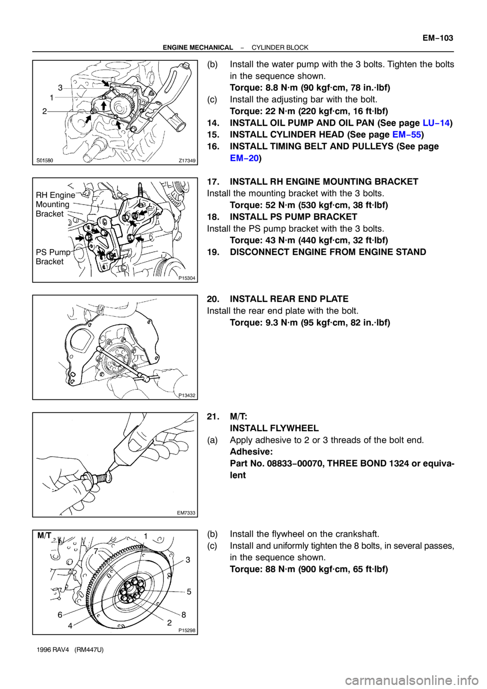
(b) Install the water pump with the 3 bolts. Tighten the bolts
in the sequence shown.
Torque: 8.8 N·m (90 kgf·cm, 78 in.·lbf)
(c) Install the adjusting bar with the bolt.
Torque: 22 N·m (220 kgf·cm, 16 ft·lbf)
14. INSTALL OIL PUMP AND OIL PAN (See page LU−14)
15. INSTALL CYLINDER HEAD (See page EM−55)
16. INSTALL TIMING BELT AND PULLEYS (See page
EM−20)
17. INSTALL RH ENGINE MOUNTING BRACKET
Install the mounting bracket with the 3 bolts.
Torque: 52 N·m (530 kgf·cm, 38 ft·lbf)
18. INSTALL PS PUMP BRACKET
Install the PS pump bracket with the 3 bolts.
Torque: 43 N·m (440 kgf·cm, 32 ft·lbf)
19. DISCONNECT ENGINE FROM ENGINE STAND
20. INSTALL REAR END PLATE
Install the rear end plate with the bolt.
Torque: 9.3 N·m (95 kgf·cm, 82 in.·lbf)
21. M/T:
INSTALL FLYWHEEL
(a) Apply adhesive to 2 or 3 threads of the bolt end.
Adhesive:
Part No. 08833−00070, THREE BOND 1324 or equiva-
lent
(b) Install the flywheel on the crankshaft.
(c) Install and uniformly tighten the 8 bolts, in several passes,
in the sequence shown.
Torque: 88 N·m (900 kgf·cm, 65 ft·lbf)
Page 770 of 1354
P15300
3
1
2 A/T
5
8 7
6
4 EM−104
− ENGINE MECHANICALCYLINDER BLOCK
1996 RAV4 (RM447U)
22. A/T:
INSTALL DRIVE PLATE
Torque: 83 N·m (850 kgf·cm, 61 ft·lbf)
Page 771 of 1354
EM0F3−03
− ENGINE MECHANICALEXHAUST SYSTEM
EM−105
1996 RAV4 (RM447U)
EXHAUST SYSTEM
COMPONENTS
Page 775 of 1354
A
B
C
D
E
F
G
H
I
J
K
L
M
N
O
P
5
B
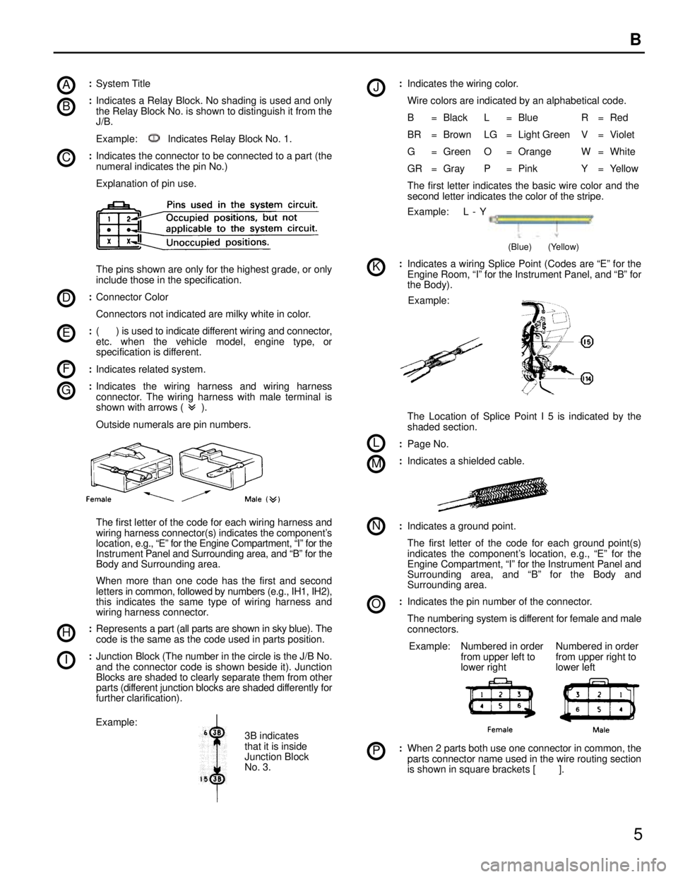
:System Title
:Indicates a Relay Block. No shading is used and only
the Relay Block No. is shown to distinguish it from the
J/B.
Example: Indicates Relay Block No. 1.
:Indicates the connector to be connected to a part (the
numeral indicates the pin No.)
Explanation of pin use.
The pins shown are only for the highest grade, or only
include those in the specification.
:Connector Color
Connectors not indicated are milky white in color.
:( ) is used to indicate different wiring and connector,
etc. when the vehicle model, engine type, or
specification is different.
:Indicates related system.
:Indicates the wiring harness and wiring harness
connector. The wiring harness with male terminal is
shown with arrows ( ).
Outside numerals are pin numbers.
The first letter of the code for each wiring harness and
wiring harness connector(s) indicates the component's
location, e.g., Eº for the Engine Compartment, Iº for the
Instrument Panel and Surrounding area, and Bº for the
Body and Surrounding area.
When more than one code has the first and second
letters in common, followed by numbers (e.g., IH1, IH2),
this indicates the same type of wiring harness and
wiring harness connector.
:Represents a part (all parts are shown in sky blue). The
code is the same as the code used in parts position.
:Junction Block (The number in the circle is the J/B No.
and the connector code is shown beside it). Junction
Blocks are shaded to clearly separate them from other
parts (different junction blocks are shaded differently for
further clarification).
3B indicates
that it is inside
Junction Block
No. 3.
Example::Indicates the wiring color.
Wire colors are indicated by an alphabetical code.
B = Black L = Blue R = Red
BR = Brown LG = Light Green V = Violet
G = Green O = Orange W = White
GR = Gray P = Pink Y = Yellow
The first letter indicates the basic wire color and the
second letter indicates the color of the stripe.
Example: L - Y
(Blue) (Yellow)
:Indicates a wiring Splice Point (Codes are Eº for the
Engine Room, Iº for the Instrument Panel, and Bº for
the Body).
Example:
The Location of Splice Point I 5 is indicated by the
shaded section.
:Page No.
:Indicates a shielded cable.
:Indicates a ground point.
The first letter of the code for each ground point(s)
indicates the component's location, e.g., Eº for the
Engine Compartment, Iº for the Instrument Panel and
Surrounding area, and Bº for the Body and
Surrounding area.
:Indicates the pin number of the connector.
The numbering system is different for female and male
connectors.
Example: Numbered in order
from upper left to
lower rightNumbered in order
from upper right to
lower left
:When 2 parts both use one connector in common, the
parts connector name used in the wire routing section
is shown in square brackets [ ].