Page 1306 of 1354
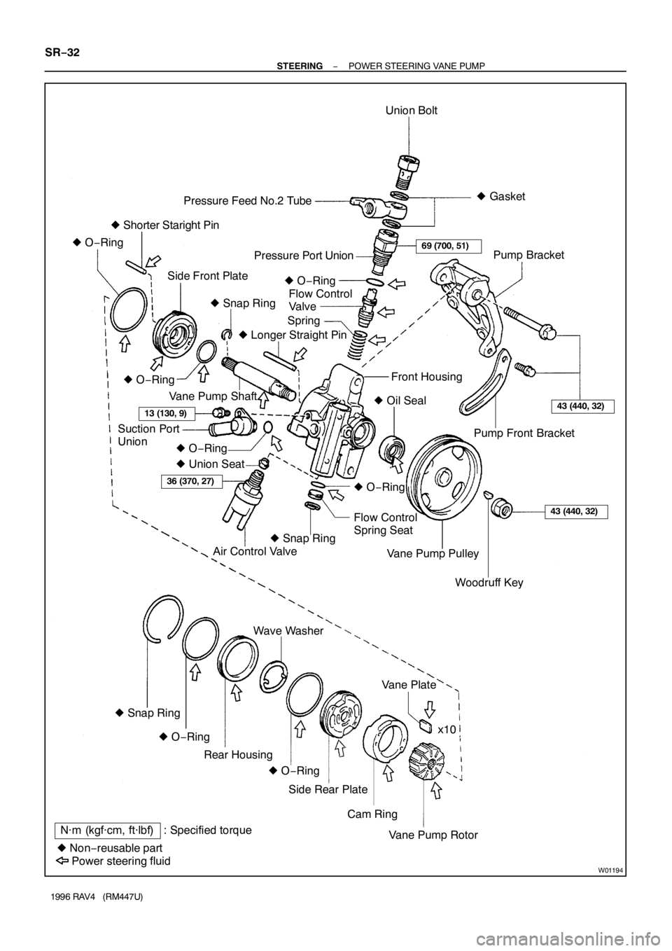
W01194
N·m (kgf·cm, ft·lbf) : Specified torque
� Non−reusable partUnion Bolt
Spring Pressure Feed No.2 Tube
Side Front PlatePressure Port Union
Flow Control
Valve
Pump Front Bracket
Flow Control
Spring Seat� Gasket
� Shorter Staright Pin
Air Control Valve � O−Ring
� Snap Ring� O−Ring
� Union Seat� Longer Straight Pin
Vane Pump Shaft
Suction Port
UnionFront Housing
� O−Ring
� Oil Seal
� O−Ring
� O−Ring
Woodruff Key Vane Pump PulleyPump Bracket
� Snap Ring
Cam Ring Side Rear PlateVane Plate Wave Washer
Vane Pump Rotorx10
Power steering fluidRear Housing
� O−Ring � O−Ring � Snap Ring
69 (700, 51)
13 (130, 9)43 (440, 32)
36 (370, 27)
43 (440, 32)
SR−32
− STEERINGPOWER STEERING VANE PUMP
1996 RAV4 (RM447U)
Page 1309 of 1354
W01800
W01803
Vinyl Tape
− STEERINGPOWER STEERING VANE PUMP
SR−35
1996 RAV4 (RM447U)
10. REMOVE REAR HOUSING, WAVE WASHER AND SIDE
REAR PLATE
(a) Using 2 screwdrivers, remove the snap ring.
(b) To prevent oil seal lip damage, wind vinyl tape on the ser-
rated part of the vane pump shaft.
(c) Using a plastic hammer, tap out the housing, washer and
plate.
(d) Remove the O−ring from the housing.
(e) Remove the O−ring from the plate.
11. REMOVE CAM RING AND 10 VANE PLATES
12. REMOVE VANE PUMP SHAFT WITH VANE PUMP RO-
TOR AND SIDE FRONT PLATE
13. REMOVE VANE PUMP ROTOR AND SIDE FRONT
PLATE
(a) Using a screwdriver, remove the snap ring from the vane
pump shaft.
(b) Remove the 2 O−rings from the plate.
14. REMOVE SHORTER STRAIGHT PIN
Using pliers, remove the pin from the side front plate.
15. REMOVE LONGER STRAIGHT PIN
Using pliers, remove the pin from the front housing.
Page 1310 of 1354

SR0FY−01
W01200
Micrometer
Caliper
Gauge
Front Housing
Vane Pump Shaft Bushing
N00372
Height
LengthThickness
R10282Feeler Gauge
R13897
Inscribed Mark
SR−36
− STEERINGPOWER STEERING VANE PUMP
1996 RAV4 (RM447U)
INSPECTION
NOTICE:
When using a vise, do not overtighten it.
1. MEASURE OIL CLEARANCE BETWEEN VANE PUMP
SHAFT AND BUSHING
Using a micrometer and a caliper gauge, measure the oil clear-
ance.
Standard clearance:
0.03 − 0.05 mm (0.0012 − 0.0020 in.)
Maximum clearance: 0.07 mm (0.0028 in.)
If it is more than the maximum, replace the front housing and
vane pump shaft.
2. INSPECT VANE PUMP ROTOR AND VANE PLATES
(a) Using a micrometer, measure the height, thickness and
length of the 10 plates.
Minimum height: 8.1 mm (0.319 in.)
Minimum thickness: 1.797 mm (0.0707 in.)
Minimum length: 14.988 mm (0.59008 in.)
(b) Using a feeler gauge, measure the clearance between
the rotor groove and plate.
Maximum clearance: 0.03 mm (0.0012 in.)
If it is more than the maximum, replace the plate and/or rotor
with one having the same mark stamped on the cam ring.
Inscribed mark: 1, 2, 3, 4 or None
Page 1312 of 1354
R08702
Calipers
W01131
Vinyl Tape
W01130
Press
SST
Oil SealSST SR−38
− STEERINGPOWER STEERING VANE PUMP
1996 RAV4 (RM447U)
4. INSPECT SPRING
Using calipers, measure the free length of the spring.
Minimum free length: 36.0 mm (1.42 in.)
If it is not within the specification, replace the spring.
5. IF NECESSARY, REPLACE OIL SEAL
(a) Using a screwdriver with vinyl tape wound around its tip,
remove the oil seal.
NOTICE:
Be careful not to damage the bushing of the front housing.
(b) Coat a new oil seal lip with power steering fluid.
(c) Using SST, press in the oil seal.
SST 09950−60010 (09951−00240),
09950−70010 (09951−07100)
NOTICE:
Make sure to install the oil seal facing the correct direction.
Page 1313 of 1354

REASSEMBLY
NOTICE:
When using a vise, do not overtighten i")
SR0FZ−01
R11274
Inscribed Mark
W01172
Longer Straight Pin
Vinyl Tape
Hole
− STEERINGPOWER STEERING VANE PUMP
SR−39
1996 RAV4 (RM447U)
REASSEMBLY
NOTICE:
When using a vise, do not overtighten it.
1. COAT WITH POWER STEERING FLUID
(See page SR−31)
2. INSTALL LONGER STRAIGHT PIN
Using a plastic hammer, tap in a new pin to the front housing.
NOTICE:
Be careful not to damage the pin.
3. INSTALL SHORTER STRAIGHT PIN
Install a new pin to the side front plate.
NOTICE:
Be careful not to damage the pin.
4. INSTALL SIDE FRONT PLATE AND VANE PUMP RO-
TOR
(a) Coat 2 new O−rings with power steering fluid and install
them to the plate.
(b) Install the plate to the pump shaft.
(c) Install the rotor to the pump shaft with the inscribed mark
facing outward.
NOTICE:
Make sure to install the plate facing the correct direction.
(d) Using snap ring pliers, install a new snap ring to the vane
pump shaft.
5. INSTALL VANE PUMP SHAFT WITH VANE PUMP RO-
TOR AND SIDE FRONT PLATE
Align the hole of the plate and longer straight pin, and tap in the
shaft with a plastic hammer.
NOTICE:
Be careful not to damage the oil seal and O−rings.
Page 1319 of 1354
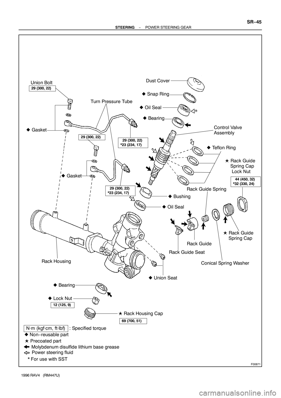
F00871
29 (300, 22)
*23 (234, 17)
� Gasket
29 (300, 22)
*23 (234, 17)
44 (450, 32)
*32 (330, 24)
Union Bolt
� Snap Ring
� Oil Seal Turn Pressure TubeDust Cover
Rack GuideControl Valve
Assembly
� Rack Guide
Spring Cap
Lock Nut � Bearing
� Lock Nut � Gasket
� Oil Seal� Teflon Ring
� Bearing� Union Seat� Bushing
� Precoated part
Molybdenum disulfide lithium base greaseRack Guide Seat� Rack Guide
Spring Cap
� Rack Housing Cap
N·m (kgf·cm, ft·lbf) : Specified torque
* For use with SST � Non−reusable part
Power steering fluid
29 (300, 22)
69 (700, 51)
12 (125, 9)
29 (300, 22)
Rack Housing
Conical Spring Washer
Rack Guide Spring
− STEERINGPOWER STEERING GEAR
SR−45
1996 RAV4 (RM447U)
Page 1320 of 1354
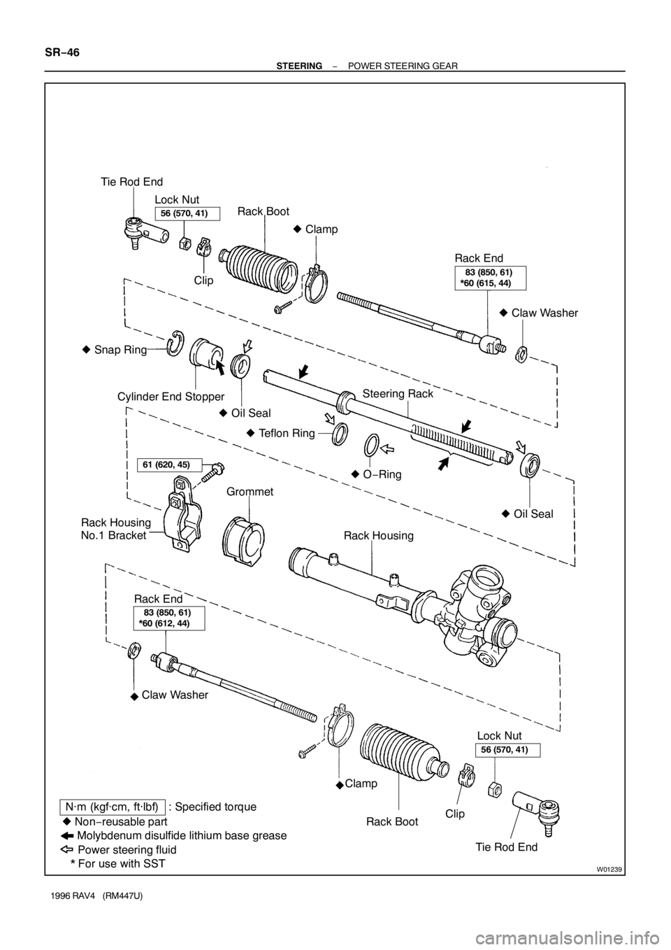
W01239
� Snap Ring
� Oil Seal Tie Rod End
Lock Nut
Rack Boot
Clip
Cylinder End Stopper
Rack Housing � Clamp
� Oil Seal � O−Ring � Teflon RingSteering RackRack End
� Claw Washer
Rack Housing
No.1 BracketGrommet
Lock Nut
Molybdenum disulfide lithium base grease
N·m (kgf·cm, ft·lbf) : Specified torque
* For use with SST � Non−reusable part
Power steering fluid
�
�
56 (570, 41)
61 (620, 45)
56 (570, 41)
83 (850, 61)
*60 (615, 44)
83 (850, 61)
*60 (612, 44)
Rack End
Claw Washer
Clamp
Rack BootClip
Tie Rod End SR−46
− STEERINGPOWER STEERING GEAR
1996 RAV4 (RM447U)
Page 1323 of 1354

6. REMOVE RACK HOUSING NO.1 BRACKET AND
GROMMET
(")
W01244
Matchmarks
W01245
SST
Rack Guide Spring
Cap Lock Nut
W01246
SST
W01247
SST
Pin
Pin
− STEERINGPOWER STEERING GEAR
SR−49
1996 RAV4 (RM447U)
6. REMOVE RACK HOUSING NO.1 BRACKET AND
GROMMET
(a) Place matchmarks on the bracket and rack housing.
(b) Remove the bolt.
(c) Remove the grommet from the rack housing No.1 brack-
et.
7. REMOVE RACK GUIDE SPRING CAP LOCK NUT
Using SST, remove the nut.
SST 09922−10010
NOTICE:
Use SST 09922−10010 in the direction shown in the illustra-
tion.
8. REMOVE RACK GUIDE SPRING CAP, RACK GUIDE
SPRING, RACK GUIDE AND RACK GUIDE SEAT
(a) Using a hexagon wrench (21 mm), remove the cap.
(b) Remove the seat from the guide.
9. REMOVE RACK HOUSING CAP
10. REMOVE LOCK NUT
Using SST to stop the control valve shaft rotating, remove the
nut.
SST 09616−00010
11. REMOVE DUST COVER
12. REMOVE CONTROL VALVE ASSEMBLY, OIL SEAL
AND BEARING
(a) Using snap ring pliers, remove the snap ring from the rack
housing.
(b) Using SST, remove the control valve with the oil seal and
bearing.
SST 09613−12010
NOTICE:
Never attempt to tap out the control valve as this would
damage it.
(c) Remove the oil seal and bearing from the control valve.
13. REMOVE BEARING
Remove the bearing and spacer from the rack housing.

10. REMOVE REAR HOUSING, WAVE WASHER AND SIDE
REAR PLATE
(a) Using 2 screwdrivers, remove the snap ring.
(b)")

4. INSPECT SPRING
Using calipers, measure the free length of the spring")