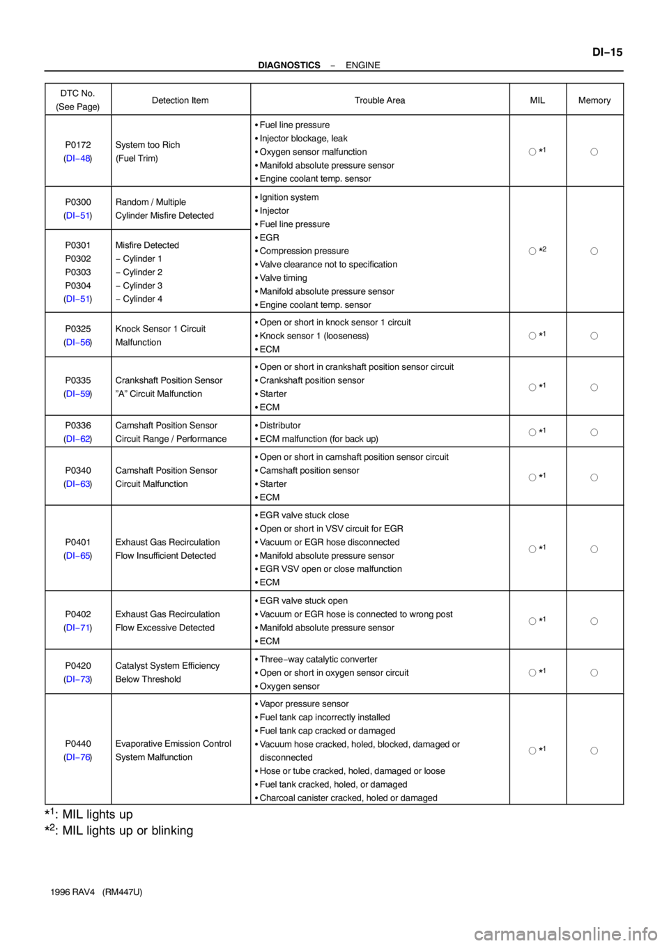
Page 335 of 1354

− DIAGNOSTICSENGINE
DI−15
1996 RAV4 (RM447U) DTC No.
(See Page)
Detection ItemTrouble AreaMILMemory
P0172
(DI−48)System too Rich
(Fuel Trim)
�Fuel line pressure
�Injector blockage, leak
�Oxygen sensor malfunction
�Manifold absolute pressure sensor
�Engine coolant temp. sensor
� *1�
P0300
(DI−51)Random / Multiple
Cylinder Misfire Detected�Ignition system
�Injector
�Fuel line pressure
�EGR
�Compression pressure
�Valve clearance not to specification
�Valve timing
�Manifold absolute pressure sensor
�Engine coolant temp. sensor
� *2�P0301
P0302
P0303
P0304
(DI−51)Misfire Detected
− Cylinder 1
− Cylinder 2
− Cylinder 3
− Cylinder 4
P0325
(DI−56)Knock Sensor 1 Circuit
Malfunction�Open or short in knock sensor 1 circuit
�Knock sensor 1 (looseness)
�ECM
� *1�
P0335
(DI−59)Crankshaft Position Sensor
”A” Circuit Malfunction
�Open or short in crankshaft position sensor circuit
�Crankshaft position sensor
�Starter
�ECM
� *1�
P0336
(DI−62)Camshaft Position Sensor
Circuit Range / Performance�Distributor
�ECM malfunction (for back up)� *1�
P0340
(DI−63)Camshaft Position Sensor
Circuit Malfunction
�Open or short in camshaft position sensor circuit
�Camshaft position sensor
�Starter
�ECM
� *1�
P0401
(DI−65)Exhaust Gas Recirculation
Flow Insufficient Detected
�EGR valve stuck close
�Open or short in VSV circuit for EGR
�Vacuum or EGR hose disconnected
�Manifold absolute pressure sensor
�EGR VSV open or close malfunction
�ECM
� *1�
P0402
(DI−71)Exhaust Gas Recirculation
Flow Excessive Detected
�EGR valve stuck open
�Vacuum or EGR hose is connected to wrong post
�Manifold absolute pressure sensor
�ECM
� *1�
P0420
(DI−73)Catalyst System Efficiency
Below Threshold�Three−way catalytic converter
�Open or short in oxygen sensor circuit
�Oxygen sensor
� *1�
P0440
(DI−76)Evaporative Emission Control
System Malfunction
�Vapor pressure sensor
�Fuel tank cap incorrectly installed
�Fuel tank cap cracked or damaged
�Vacuum hose cracked, holed, blocked, damaged or
disconnected
�Hose or tube cracked, holed, damaged or loose
�Fuel tank cracked, holed, or damaged
�Charcoal canister cracked, holed or damaged
� *1�
*1: MIL lights up
*
2: MIL lights up or blinking
Page 359 of 1354

FI6606FI7210A06619
Atmosphere
Flange
Platinum Electrode
Solid Electrolyte
(Zirconia Element)
Platinum Electrode
Coating (Ceramic)
Richer−air Fuel Ratio−Leaner Ideal Air−Fuel Mixture
Output Voltage
Cover
Exhaust Gas
− DIAGNOSTICSENGINE
DI−39
1996 RAV4 (RM447U)
DTC P0125 Insufficient Coolant Temp. for Closed Loop
Fuel Control
CIRCUIT DESCRIPTION
To obtain a high purification rate for the CO, HC and NOx components of the exhaust gas, a three−way cata-
lytic converter is used, but for the most efficient use of the three−way catalytic converter, the air−fuel ratio
must be precisely controlled so that it is always close to the stoichiometric air−fuel ratio.
The oxygen sensor has the characteristic whereby its output voltage changes suddenly in the vicinity of the
stoichiometric air−fuel ratio. This characteristic is used to detect the oxygen concentration in the exhaust
gas and provide feedback to the computer for control of the air−fuel ratio.
When the air−fuel ratio becomes LEAN, the oxygen concentration in the exhaust increases and the oxygen
sensor informs the ECM of the LEAN condition (small electromotive force: 0 V).
When the air−fuel ratio is RICHER than the stoichiometric air−fuel ratio the oxygen concentration in the ex-
haust gas is reduced and the oxygen sensor informs the ECM of the RICH condition (large electromotive
force: 1 V).
The ECM judges by the electromotive force from the oxygen sensor whether the air−fuel ratio is RICH or
LEAN and controls the injection time accordingly. However, if malfunction of the oxygen sensor causes out-
put of abnormal electromotive force, the ECM is unable to perform accurate air−fuel ratio control.
DTC No.DTC Detecting ConditionTrouble Area
P0125
After the engine is warmed up, oxygen sensor output does not
indicate RICH even once when conditions (a), (b), and (c)
continue for at least 1.5 minutes
(a) Engine speed: 1,500 rpm or more
(b) Vehicle speed: 40 ∼ 100 km/h (25 ∼ 62 mph)
(c) Throttle valve does not fully closed
�Open or short in oxygen sensor circuit
�oxygen sensor
HINT:
After confirming DTC P0125 use the OBDII scan tool or TOYOTA hand−held tester to confirm voltage output
of oxygen sensor from ”CURRENT DATA”.
If voltage output of oxygen sensor is 0 V, oxygen sensor circuit may be open or short.
DI3ZJ−01
Page 654 of 1354
EC05E−01
− EMISSION CONTROLEMISSION CONTROL SYSTEM
EC−1
1996 RAV4 (RM447U)
EMISSION CONTROL SYSTEM
PURPOSE
The emission control systems are installed to reduce the amount of HC, CO and NOx exhausted from the
engine ((3), (4) and (5)), to prevent the atmospheric release of blow−by gas−containing HC (1) and evapo-
rated fuel containing HC being released from the fuel tank (2).
The function of each system is shown in the following table.
SystemAbbreviationFunction
(1) Positive Crankcase Ventilation
(2) Evaporative Emission Control
(3) Exhaust Gas Recirculation
(4) Three−Way Catalytic Converter
(5) Sequential Multiport Fuel Injection*PCV
EVAP
EGR
TWC
SFIReduces HC
Reduces evaporated HC
Reduces NOx
Reduces HC, CO and NOx
Injects a precisely timed, optimum amount of fuel for reduced
exhaust emissions
Remark: * For inspection and repair of the SFI system, refer to the SFI section in this manual.
Page 664 of 1354
EC0FI−02
− EMISSION CONTROLTHREE−WAY CATALYTIC CONVERTER (TWC)
SYSTEMEC−11
1996 RAV4 (RM447U)
THREE−WAY CATALYTIC CONVERTER (TWC) SYSTEM
COMPONENTS
Page 665 of 1354
EC−12− EMISSION CONTROLTHREE−WAY CATALYTIC CONVERTER (TWC)
SYSTEM
1996 RAV4 (RM447U)
Page 666 of 1354
EC05M−02
− EMISSION CONTROLTHREE−WAY CATALYTIC CONVERTER (TWC)
SYSTEMEC−13
1996 RAV4 (RM447U)
INSPECTION
1. CHECK CONNECTIONS FOR LOOSENESS OR DAMAGE
2. CHECK CLAMPS FOR WEAKNESS, CRACKS OR DAMAGE
3. CHECK FOR DENTS OR DAMAGE
If any part of the protector is damaged or dented to the extent that it contacts the TWC, repair or replace
it.
4. CHECK HEAT INSULATOR FOR DAMAGE
5. CHECK FOR ADEQUATE CLEARANCE BETWEEN CATALYTIC CONVERTER AND HEAT INSU-
LATOR