Page 1129 of 1354
− SUSPENSION AND AXLEFRONT AXLE HUB
SA−15
1996 RAV4 (RM447U)
7. INSTALL LOWER BALL JOINT
(a) Install the lower ball joint and torque the nut.
Torque: 127 N·m (1,300 kgf·cm, 94 ft·lbf)
(b) Install a new cotter pin.
Page 1131 of 1354
SA0TE−01
R10733
SST
R10759
− SUSPENSION AND AXLEFRONT WHEEL HUB BOLT
SA−17
1996 RAV4 (RM447U)
FRONT WHEEL HUB BOLT
REPLACEMENT
1. REMOVE FRONT WHEEL
2. REMOVE FRONT BRAKE CALIPER AND DISC
(a) Remove the 2 bolts and brake caliper from the steering
knuckle.
(b) Support the brake caliper securely and remove the disc.
3. REMOVE HUB BOLT
Using SST, remove the hub bolt.
SST 09628−10011
4. INSTALL HUB BOLT
(a) Install a washer and nut to the hub bolt, as shown in the
illustration.
(b) Install the hub bolt with torquing the nut.
5. INSTALL FRONT BRAKE DISC AND CALIPER
Install the disc and brake caliper with the 2 bolts.
Torque: 107 N·m (1,090 kgf·cm, 79 ft·lbf)
HINT:
Check the disc runout (See page BR−26).
6. INSTALL FRONT WHEEL
Torque: 103 N·m (1,050 kgf·cm 76 ft·lbf)
Page 1132 of 1354
SA0TF−06
W04172
2WD M/T
Snap RingCenter Bearing Bracket
RH Drive Shaft
Snap RingABS Speed Sensor
Tie Rod End
Cotter Pin
Lock Cap LH Drive Shaft
Boot Clamp
Engine
Under
Cover
3 Door vehicle
64 (650, 47)
5 Door vehicle,
All over fender
vehicle
113 (1,150, 83)
�
�
32 (330, 24)
64 (650, 47)
8 (80, 69 in.·lbf)
49 (500, 36)
216 (2,200, 159)
127 (1,300, 94)
Lower Suspension Arm X6
X7
Center Drive Shaft Inner Race Ball Cage Stabilizer Bar Link
Snap Ring
Snap Ring
Dust Cover
Center Bearing Dust Cover
Inboard Joint Tulip Outboard Joint
Shaft No.2 Dust
DeflectorBoot�
�
�
�
�
� �
�N·m (kgf·cm, ft·lbf)
: Specified torque
Non−reusable part
LH SA−18
− SUSPENSION AND AXLEFRONT DRIVE SHAFT
1996 RAV4 (RM447U)
FRONT DRIVE SHAFT
COMPONENTS
Page 1134 of 1354

SA1YB−02
FA1535
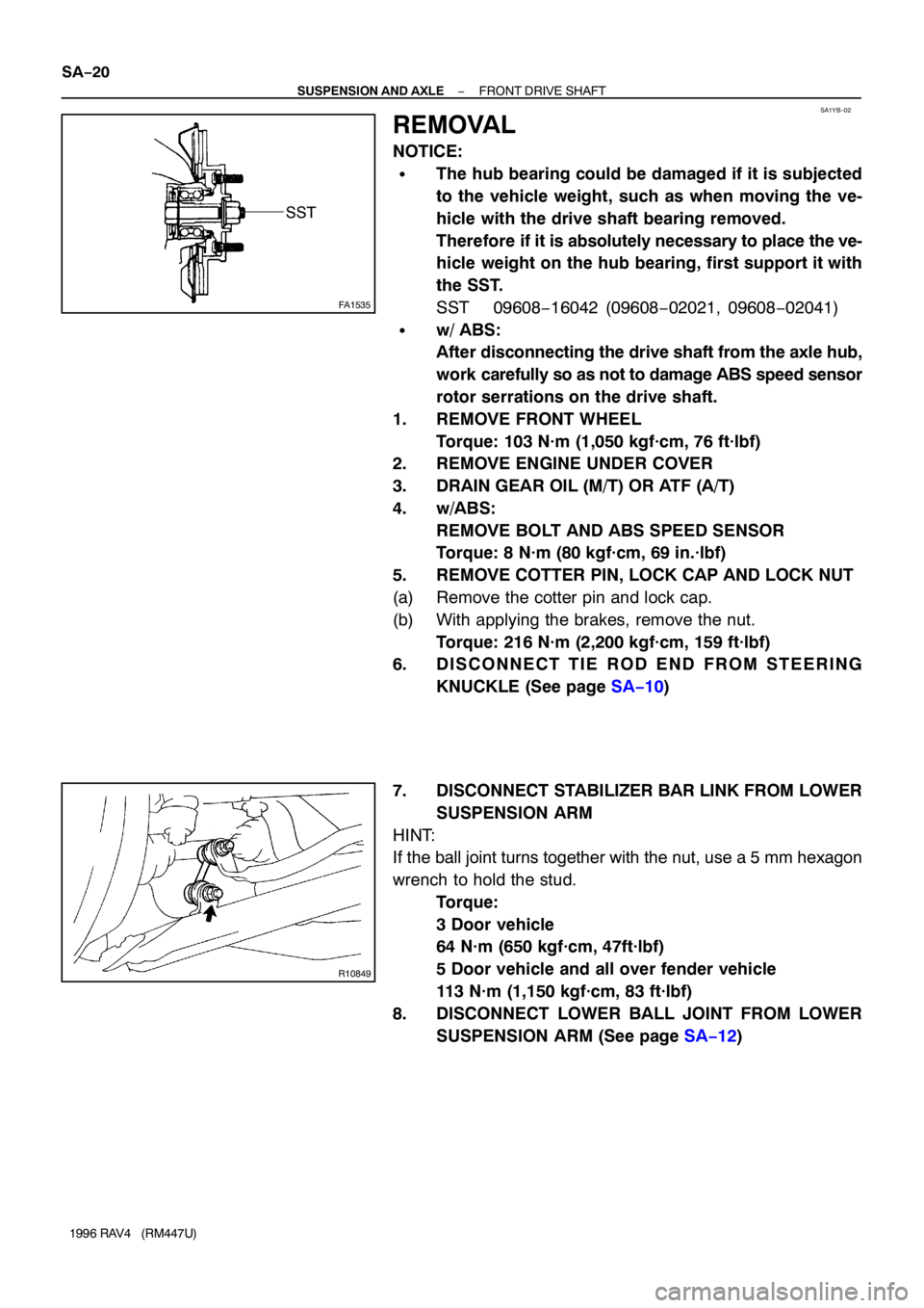
SST
R10849
SA−20
− SUSPENSION AND AXLEFRONT DRIVE SHAFT
1996 RAV4 (RM447U)
REMOVAL
NOTICE:
�The hub bearing could be damaged if it is subjected
to the vehicle weight, such as when moving the ve-
hicle with the drive shaft bearing removed.
Therefore if it is absolutely necessary to place the ve-
hicle weight on the hub bearing, first support it with
the SST.
SST 09608−16042 (09608−02021, 09608−02041)
�w/ ABS:
After disconnecting the drive shaft from the axle hub,
work carefully so as not to damage ABS speed sensor
rotor serrations on the drive shaft.
1. REMOVE FRONT WHEEL
Torque: 103 N·m (1,050 kgf·cm, 76 ft·lbf)
2. REMOVE ENGINE UNDER COVER
3. DRAIN GEAR OIL (M/T) OR ATF (A/T)
4. w/ABS:
REMOVE BOLT AND ABS SPEED SENSOR
Torque: 8 N·m (80 kgf·cm, 69 in.·lbf)
5. REMOVE COTTER PIN, LOCK CAP AND LOCK NUT
(a) Remove the cotter pin and lock cap.
(b) With applying the brakes, remove the nut.
Torque: 216 N·m (2,200 kgf·cm, 159 ft·lbf)
6. D I S C O N N E C T T I E R O D E N D F R O M S T E E R I N G
KNUCKLE (See page SA−10)
7. DISCONNECT STABILIZER BAR LINK FROM LOWER
SUSPENSION ARM
HINT:
If the ball joint turns together with the nut, use a 5 mm hexagon
wrench to hold the stud.
Torque:
3 Door vehicle
64 N·m (650 kgf·cm, 47ft·lbf)
5 Door vehicle and all over fender vehicle
113 N·m (1,150 kgf·cm, 83 ft·lbf)
8. DISCONNECT LOWER BALL JOINT FROM LOWER
SUSPENSION ARM (See page SA−12)
Page 1135 of 1354

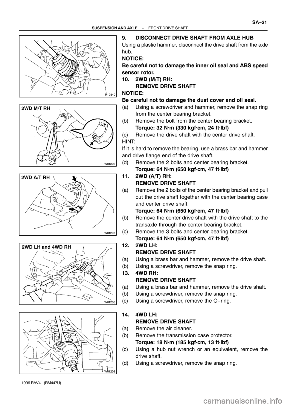
R10840
W01206
2WD M/T RH
W01207
2WD A/T RH
W01208
2WD LH and 4WD RH
W01209
− SUSPENSION AND AXLEFRONT DRIVE SHAFT
SA−21
1996 RAV4 (RM447U)
9. DISCONNECT DRIVE SHAFT FROM AXLE HUB
Using a plastic hammer, disconnect the drive shaft from the axle
hub.
NOTICE:
Be careful not to damage the inner oil seal and ABS speed
sensor rotor.
10. 2WD (M/T) RH:
REMOVE DRIVE SHAFT
NOTICE:
Be careful not to damage the dust cover and oil seal.
(a) Using a screwdriver and hammer, remove the snap ring
from the center bearing bracket.
(b) Remove the bolt from the center bearing bracket.
Torque: 32 N·m (330 kgf·cm, 24 ft·lbf)
(c) Remove the drive shaft with the center drive shaft.
HINT:
If it is hard to remove the bearing, use a brass bar and hammer
and drive flange end of the drive shaft.
(d) Remove the 2 bolts and center bearing bracket.
Torque: 64 N·m (650 kgf·cm, 47 ft·lbf)
11. 2WD (A/T) RH:
REMOVE DRIVE SHAFT
(a) Remove the 2 bolts of the center bearing bracket and pull
out the drive shaft together with the center bearing case
and center drive shaft.
Torque: 64 N·m (650 kgf·cm, 47 ft·lbf)
(b) Remove the center drive shaft with the drive shaft to the
transaxle through the center bearing bracket.
(c) Remove the 3 bolts and center bearing bracket.
Torque: 64 N·m (650 kgf·cm, 47 ft·lbf)
12. 2WD LH:
REMOVE DRIVE SHAFT
(a) Using a brass bar and hammer, remove the drive shaft.
(b) Using a screwdriver, remove the snap ring.
13. 4WD RH:
REMOVE DRIVE SHAFT
(a) Using a brass bar and hammer, remove the drive shaft.
(b) Using a screwdriver, remove the snap ring.
(c) Using a screwdriver, remove the O−ring.
14. 4WD LH:
REMOVE DRIVE SHAFT
(a) Remove the air cleaner.
(b) Remove the transmission case protector.
Torque: 18 N·m (185 kgf·cm, 13 ft·lbf)
(c) Using a hub nut wrench or an equivalent, remove the
drive shaft.
(d) Using a screwdriver, remove the snap ring.
Page 1146 of 1354
SA0TK−03
Z19329
Suspension
Support
No.2
CapSpring Upper Seat
Spring
Bumper
Lower
Insulator
Shock Absorber Coil Spring Upper
Insulator
ABS Speed
Sensor Suspension
Support
Dust Seal Shock Absorber
with Coil Spring
Front Drive Shaft
Flexible Hose
Tie Rod End
Cotter Pin
Disc
Cotter Pin
Lock Cap
Lower Ball JointCotter Pin
Brake Caliper
Lower Suspension Arm80 (820, 59)
47 (475, 34)
5 (55, 48 in.·lbf)
158 (1,610, 117)
107 (1,090, 79)
127 (1,300, 94)
49 (500, 36)
216 (2,200, 159)
127 (1,300, 94)
19 (192, 14)
8 (80, 69 in.·lbf)
Dust Deflector
� �
�
� �
�N·m (kgf·cm, ft·lbf): Specified torque
Non−reusable part
SA−32
− SUSPENSION AND AXLEFRONT SHOCK ABSORBER
1996 RAV4 (RM447U)
FRONT SHOCK ABSORBER
COMPONENTS
Page 1147 of 1354
SA0TL−03
R10850
R10823
− SUSPENSION AND AXLEFRONT SHOCK ABSORBER
SA−33
1996 RAV4 (RM447U)
REMOVAL
1. REMOVE FRONT WHEEL
Torque: 103 N·m (1,050 kgf·cm, 76 ft·lbf)
2. DISCONNECT FLEXIBLE HOSE AND ABS SPEED
SENSOR WIRE HARNESS (w/ ABS) FROM SHOCK
ABSORBER
Remove the 2 bolts and disconnect the flexible hose and ABS
speed sensor wire harness.
Torque:
Flexible hose: 19 N·m (192 kgf·cm, 14 ft·lbf)
ABS wire harness: 5 N·m (55 kgf·cm, 48 in.·lbf)
3. DISCONNECT SHOCK ABSORBER FROM STEERING
KNUCKLE
Torque: 158 N·m (1,610 kgf·cm, 117 ft·lbf)
HINT:
At the time of installation, please refer to the following item.
Coat the nut’s threads with engine oil.
4. REMOVE SHOCK ABSORBER WITH COIL SPRING
Remove the 3 nuts, suspension support No.2 and shock ab-
sorber with the coil spring.
Torque: 80 N·m (820 kgf·cm, 59 ft·lbf)
Page 1151 of 1354

SA0TP−01
R10846
SST
Vinyl Tape
R10826
R10825
SST
R10848
MP Grease
− SUSPENSION AND AXLEFRONT SHOCK ABSORBER
SA−37
1996 RAV4 (RM447U)
REASSEMBLY
1. INSTALL LOWER INSULATOR ONTO SHOCK AB-
SORBER
2. INSTALL SPRING BUMPER TO PISTON ROD
3. INSTALL COIL SPRING AND SUSPENSION SUPPORT
(a) Using SST, compress the coil spring.
SST 09727−30021
HINT:
To prevent the coil spring from damaging, wind vinyl tape on the
coil spring.
NOTICE:
Do not use an impact wrench. It will damage the SST.
(b) Install the coil spring to the shock absorber.
HINT:
Fit the lower end of the coil spring into the gap of lower spring
seat of the shock absorber.
(c) Align the tab of spring upper seat with the tabs of the up-
per insulator.
(d) Install the spring upper seat with upper insulator to the
shock absorber with the ’OUT’ mark facing the outside of
the vehicle.
(e) Install the dust seal and suspension support.
(f) Using SST to hold the spring upper seat, install a new nut.
SST 09729−22031
Torque: 47 N·m (475 kgf·cm, 34 ft·lbf)
(g) Remove the SST.
(h) Pack MP grease into the suspension support.
(i) Install the cap.