Page 1065 of 1354

1996 RAV4 (RM447U)
(g) Measure the Plastigage at its widest point.
Standard clearance: 0.16−0.25 mm (0.006−0.01")
Q06273
Q06274
Q06214Matchmarks MX−70
− MANUAL TRANSAXLEDIFFERENTIAL CASE (4WD)
1996 RAV4 (RM447U)
(g) Measure the Plastigage at its widest point.
Standard clearance: 0.16−0.25 mm (0.006−0.010 in.)
(h) Refer to the table below, select the No.2 thrust washer
which will ensure that the backlash is within the specifica-
tion. Try to select a washer of the same size.
MarkThickness mm (in.)MarkThickness mm (in.)
−0.80 (0.0315)−1.15 (0.0453)
−0.85 (0.0335)−1.20 (0.0472)
−0.90 (0.0354)−1.25 (0.0492)
−0.95 (0.0374)−1.30 (0.0512)
−1.00 (0.0394)−1.35 (0.0531)
−1.05 (0.0413)−1.40 (0.0551)
−1.10 (0.0433)−−
(i) Remove the No.2 differential case, No.2 side gear thrust
washer and (temporarily install) a 1.0 mm (0.039 in.) thick
No.2 side gear thrust washer.
11. ASSEMBLE NO.2 DIFFERENTIAL CASE
(a) Install the No.2 side gear thrust washer (previously se-
lected) and conical spring washer to the front differential
case.
HINT:
Be careful not to mistake the direction of the conical spring
washer.
(b) Install the No.2 differential case to the No.1 differential
case.
HINT:
Align the matchmarks on the No.2 differential case and connect
the No.1 differential case.
(c) Install and torque the 16 bolts.
Torque: 124 N·m (1,260 kgf·cm, 91 ft·lbf)
12. ADJUST DIFFERENTIAL CASE SIDE BEARING PRE-
LOAD
(a) Install the differential case assembly to the transaxle
case.
(b) Install the transmission case.
HINT:
If necessary, tap on the transmission case with a plastic ham-
mer.
(c) Install and torque the 17 bolts.
Torque: 29 N·m (300 kgf·cm, 22 ft·lbf)
Page 1072 of 1354
MX065−01
D01958
Shift Lever Knob
Side Trim Cover
Side Trim Cover
Shift Control Cable Grommet Retainer
Shift Lever Assembly Select Control Cable
N·m (kgf·cm, ft·lbf) : Specified torqueWasherClip
Washer GrommetRetainerConsole Box Boot
12 (120, 9)
4.9 (50, 43 in.·lbf)
4.9 (50, 43 in.·lbf)
Clip Clip
Clip
Clip
ClipWasher
Bracket
− MANUAL TRANSAXLESHIFT LEVER AND CONTROL CABLE
MX−77
1996 RAV4 (RM447U)
SHIFT LEVER AND CONTROL CABLE
COMPONENTS
Page 1073 of 1354
MX066−01
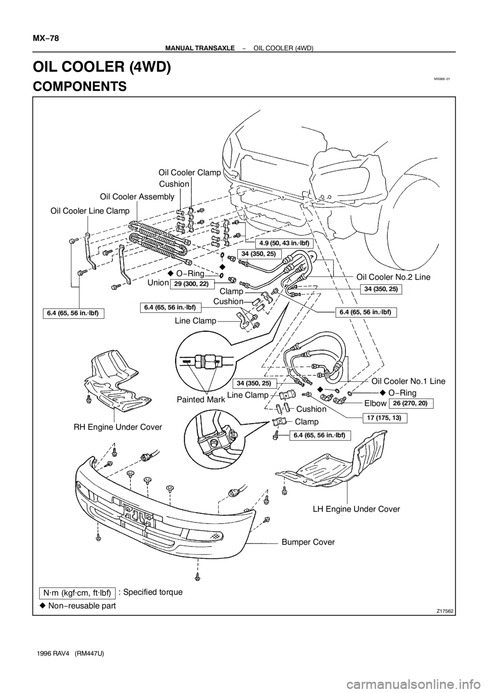
Z17562
Oil Cooler Clamp
Cushion
Oil Cooler Assembly
Oil Cooler Line Clamp
� O−Ring
Union
LH Engine Under Cover
� Non−reusable partOil Cooler No.2 Line
Painted Mark Line Clamp
Oil Cooler No.1 Line
: Specified torque
N·m (kgf·cm, ft·lbf)Bumper Cover RH Engine Under Cover
17 (175, 13)
34 (350, 25)
4.9 (50, 43 in.·lbf)
29 (300, 22)34 (350, 25)
6.4 (65, 56 in.·lbf)
� O−Ring
Elbow
26 (270, 20)
6.4 (65, 56 in.·lbf)
ClampCushion
6.4 (65, 56 in.·lbf)6.4 (65, 56 in.·lbf)CushionClamp
� �
Line Clamp
34 (350, 25)
MX−78
− MANUAL TRANSAXLEOIL COOLER (4WD)
1996 RAV4 (RM447U)
OIL COOLER (4WD)
COMPONENTS
Page 1074 of 1354
MX0C1−01
Q09037
Adjusting Shim
Transfer Oil PipeExtension Housing
x6
Dust Deflector
Transfer Pinion Bearing
Cage Assembly
Differential Lock
Indicator Switch Cushion
Differential Bearing
Adjusting Nut
Ring Gear Mounting
Case Assembly
Bearing Outer Race
Plate Washer
Transfer Left Case
Drain Plug Snap Ring
Shift Fork Shaft
Differential
Side Gear
Shaft Holder
Side Gear Shaft
Holder Bearing
Snap Ring
Adjusting Nut Lock Plate
N·m (kgf·cm, ft·lbf): Specified torque
Non−reusable part
Precoated part �
�x10Transfer Right CaseDifferential Lock
Sleeve Differential Lock
Shift Fork Plug
Transfer Inspection
Hole Cover O−Ring
�
Plug
Oil Seal Dust BootGasket
� Oil Seal
44 (450, 33)
��
�
39 (400, 29)
�
16 (160, 12)
Gasket
�
39 (400, 29)
Gasket �
25 (250, 18)
40 (410, 30)16 (160, 12)
�
25 (260, 19)
Dynamic Damper
25 (260, 19)
� Bearing
Outer Race ��
13 (130, 9)
O−Ring �
39 (400, 29)Oil Seal
�
− MANUAL TRANSAXLETRANSFER (4WD)
MX−79
1996 RAV4 (RM447U)
TRANSFER (4WD)
COMPONENTS
Page 1076 of 1354
Z17564
Left Side Bearing
Right Side Bearing
Ring Gear Mounting Case
Transfer Ring Gear
N·m (kgf·cm, ft·lbf) : Specified torque
� Non−reusable partx12
� �
97 (985, 71)
− MANUAL TRANSAXLETRANSFER (4WD)
MX−81
1996 RAV4 (RM447U)
Page 1082 of 1354
Z12390
1.5 ± 0.4 mm SST
Z12536
Z12392
SST
Q06138
Q06139
− MANUAL TRANSAXLETRANSFER (4WD)
MX−87
1996 RAV4 (RM447U)
4. REPLACE EXTENSION HOUSING OIL SEAL
(a) Using a screwdriver, remove the oil seal.
(b) Using SST and a hammer, drive in a new oil seal.
SST 09325−20010
Oil seal depth: 1.5 ± 0.4 mm (0.059 ± 0.016 in.)
(c) Coat the lip of oil seal with MP grease.
5. REPLACE SIDE GEAR SHAFT HOLDER BEARING
(a) Using a snap ring expander, remove the snap ring.
(b) Using a press, remove the bearing from the side gear
shaft holder.
(c) Using SST and a press, install a new bearing.
SST 09316−60011 (09316−00011)
(d) Using a snap ring expander, install the snap ring.
6. REPLACE TRANSFER OIL PIPE
(a) Remove the bolt and oil pipe from the transfer left case.
(b) Using a screwdriver, remove the cushion.
(c) Install a new cushion.
(d) Install the oil pipe.
(e) Install and torque the bolt.
Torque: 13 N·m (130 kgf·cm, 9 ft·lbf)
Page 1084 of 1354

MX−89
1996 RAV4 (RM447U)
REASSEMBLY
NOTICE:
When working with FIPG material, you must observe the follow-
ing items.
�Usi")
MX0C3−02
Z12547
Z12399
SST
Q08203
SST
− MANUAL TRANSAXLETRANSFER (4WD)
MX−89
1996 RAV4 (RM447U)
REASSEMBLY
NOTICE:
When working with FIPG material, you must observe the follow-
ing items.
�Using a razor blade and gasket scraper, remove all the old
FIPG material from the gasket surfaces.
�Thoroughly clean all components to remove all the loose
material.
�Clean both sealing surfaces with a non−residue solvent.
�Apply FIPG in an approx. 1 mm (0.04 in.) wide bead along
the sealing surface.
�Parts must be assembled within 10 minutes of application.
Otherwise, the FIPG material must be removed and reap-
plied.
HINT:
Coat all of the sliding and rotating surfaces with gear oil before
reassembly.
1. ASSEMBLE TRANSFER PINION BEARING CAGE
(a) Install the transfer pinion bearing cage.
(1) Install a new bearing spacer.
HINT:
Insert the spacer with the smaller diameter facing upwards.
(2) Using SST and a press, install the rear bearing.
HINT:
Press down until the pinion can move slightly up and down.
SST 09316−60011 (09316−00021)
(b) Adjust the driven pinion preload.
(1) Using SST, install and torque a new lock nut.
SST 09326−20011
Torque: 95 N·m (968 kgf·cm, 70 ft·lbf)
HINT:
�Use a torque wrench with a fulcrum length of 38 cm (14.96
in.).
�The torque specification for without using SST is 108 N·m
(1,100 kgf·cm, 80 ft·lbf).
Page 1085 of 1354

1996 RAV4 (RM447U)
(2) Using SST and a spring tension gauge, measure
the driven pinion preload.
SST 09326−20011
HINT:
Turn the driven pinion r")
Z12401
SST MX−90
− MANUAL TRANSAXLETRANSFER (4WD)
1996 RAV4 (RM447U)
(2) Using SST and a spring tension gauge, measure
the driven pinion preload.
SST 09326−20011
HINT:
Turn the driven pinion right and left 2 or 3 times to allow the
bearing to settle.
Preload (at starting):
New bearing
17.7 − 28.4 N (1.8 − 2.9 kgf, 4.0 − 6.4 lbf)
Reused bearing
4.9 − 8.8 N (0.9 − 1.4 kgf, 1.1 − 2.0 lbf)
�If the preload exceeds than the specification, re-
place the bearing spacer.
�If the preload is less than the specification, retighten
the nut 5−10° gradually a time until the specified
preload is reached.
�If the maximum torque is exceeded while retighten-
ing the nut, replace the bearing spacer and repeat
the preload procedure. Do not back off the pinion
nut to reduce the preload.
Torque: 214 N·m (2,184 kgf·cm, 158 ft·lbf) or less
HINT:
�Use a torque wrench with a fulcrum length of 50 cm (19.69
in.).
�The maximum torque specification for without using SST
is 235 N·m (2,400 kgf·cm, 174 ft·lbf).
(c) Stake the lock nut.
2. ASSEMBLE RING GEAR MOUNTING CASE
(a) Install the transfer ring gear.
(1) Clean the contact surface of the mounting case.
(2) Heat the ring gear to about 100°C (212°F) in boiling
water.
(3) Carefully take the ring gear out of the water.
(4) Clean the contact surface of the ring gear with
cleaning solvent.
(5) Quickly install the ring gear on the mounting case.
HINT:
Align the matchmarks on the mounting case and connect the
ring gear.
(6) Install and torque the 12 bolts.
Torque: 97 N·m (985 kgf·cm, 71 ft·lbf)
(b) Checking the ring gear runout (See page MX−82).
 : Specified torqueWasherClip
W")


MX−87
1996 RAV4 (RM447U)
4. REPLACE EXTENSION HOUSING OIL SEAL
(a) Using a screwdriver, remove the oil s")