Page 1086 of 1354
Q06162
SST
Q06163
SST
− MANUAL TRANSAXLETRANSFER (4WD)
MX−91
1996 RAV4 (RM447U)
(c) Install the mounting case left side bearing.
Using SST and a press, install a new left side bearing.
SST 09316−20011
(d) Install the mounting case right side bearing.
Using SST and a press, install a new right side bearing.
SST 09316−20011
3. ADJUST RING GEAR BACKLASH
(a) Install the adjusting shim to the transfer pinion bearing
cage assembly.
HINT:
First install a shim of the same thickness as before.
(b) Install the transfer pinion bearing cage assembly to the
transfer left case.
(c) Install and torque the 6 bolts.
Torque: 39 N·m (400 kgf·cm, 29 kgf·cm)
HINT:
Do not install the O−ring.
(d) Install the ring gear mounting case assembly to the trans-
fer left case.
Page 1087 of 1354

1996 RAV4 (RM447U)
(e) Using a dial indicator, measure the ring gear backlash.
Backlash: 0.13 − 0.18 mm (0.0051 − 0.0071 in.)
(f) Ref")
Q06149
Q06150
SST MX−92
− MANUAL TRANSAXLETRANSFER (4WD)
1996 RAV4 (RM447U)
(e) Using a dial indicator, measure the ring gear backlash.
Backlash: 0.13 − 0.18 mm (0.0051 − 0.0071 in.)
(f) Refer to the table below, select a plate washer which will
ensure that the backlash is within the specification. Try to
select a washer of the same size.
HINT:
The backlash will change about 0.02 mm (0.0008 in.) with every
0.03 mm (0.0012 in.) change in shim thickness.
MarkThickness mm (in.)MarkThickness mm (in.)
12.13 (0.0839)132.49 (0.0980)
22.16 (0.0850)142.52 (0.0992)
32.19 (0.0862)152.55 (0.1004)
42.22 (0.0874)162.58 (0.1016)
52.25 (0.0886)172.61 (0.1028)
62.28 (0.0898)182.64 (0.1039)
72.31 (0.0909)192.67 (0.1051)
82.34 (0.0921)202.70 (0.1063)
92.37 (0.0933)212.73 (0.1075)
102.40 (0.0945)222.76 (0.1087)
112.43 (0.0957)232.79 (0.1098)
122.46 (0.0968)242.82 (0.1110)
4. ADJUST TOTAL PRELOAD
(a) Install the transfer right case.
(b) Install and torque the 10 bolts.
Torque: 44 N·m (450 kgf·cm, 33 ft·lbf)
(c) Adjust the total preload by tightening the differential bear-
ing adjusting nut.
(d) Using SST, tighten the differential bearing adjusting nut.
SST 09318−20010
HINT:
While measuring the preload, tighten the adjusting nut a little at
a time.
Page 1090 of 1354

MX−95
1996 RAV4 (RM447U)
9. INSTALL TRANSFER PINION BEARING CAGE AS-
SEMBLY
(a) Coat the O−ring with gear oil.
(b) Ins")
Q06135
Q06166
SST
Q06287
SST
Q06168
FIPG
− MANUAL TRANSAXLETRANSFER (4WD)
MX−95
1996 RAV4 (RM447U)
9. INSTALL TRANSFER PINION BEARING CAGE AS-
SEMBLY
(a) Coat the O−ring with gear oil.
(b) Install the O−ring to the transfer pinion bearing cage.
(c) Install the transfer pinion bearing cage with the adjusting
shim (previously selected) to the transfer left case.
(d) Install and torque the 6 bolts.
Torque: 39 N·m (400 kgf·cm, 29 ft·lbf)
10. INSTALL RING GEAR MOUNTING CASE ASSEMBLY
11. INSTALL ADJUSTING NUT LOCK PLATE
Using snap ring pliers, install the lock plate so that the projection
from the lock plate fits properly into the groove of the adjusting
nut.
12. INSTALL DIFFERENTIAL SIDE GEAR SHAFT HOLD-
ER
(a) Using SST and a press, install the differential side gear
shaft holder to the transfer right case.
SST 09316−20011
(b) Using snap ring pliers, install the snap ring.
13. INSTALL TRANSFER RIGHT CASE OIL SEAL
(a) Using SST and a hammer, drive in a new oil seal.
SST 09223−15020, 09950−70010 (09951−07150)
(b) Coat the lip of the oil seal with MP grease.
14. INSTALL TRANSFER RIGHT CASE
(a) Apply FIPG to the transfer left case, as shown.
FIPG:
Part No. 08826−00090, THREE BOND 1281 or equiva-
lent
(b) Apply sealant to the bolt threads.
Sealant:
Part No. 08833−00080, THREE BOND 1344, LOCTITE
242 or equivalent
(c) Install and torque the 10 bolts.
Page 1091 of 1354

1996 RAV4 (RM447U)
Torque: 44 N·m (450 kgf·cm, 33 ft·lbf)
15. CHECK TOTAL PRELOAD (See step 4)
16. INSTALL DIFFERENTIAL LOCK S")
Q06133
Q06169
FIPG
Q06131
MX−96
− MANUAL TRANSAXLETRANSFER (4WD)
1996 RAV4 (RM447U)
Torque: 44 N·m (450 kgf·cm, 33 ft·lbf)
15. CHECK TOTAL PRELOAD (See step 4)
16. INSTALL DIFFERENTIAL LOCK SHIFT FORK, LOCK
SLEEVE AND SHIFT FORK SHAFT
(a) Install the shift fork, shift fork shaft and lock sleeve.
(b) Install and torque the bolt.
Torque: 16 N·m (160 kgf·cm, 12 ft·lbf)
17. INSTALL TRANSFER INSPECTION HOLE COVER
(a) Apply FIPG to the transfer left case, as shown.
FIPG:
Part No. 08826−00090, THREE BOND 1281 or equiva-
lent
(b) Install the cover on the transfer left case.
(c) Install and torque the 3 bolts.
Torque: 16 N·m (160 kgf·cm, 12 ft·lbf)
18. INSTALL PLUG AND DIFFERENTIAL LOCK INDICA-
TOR SWITCH
(a) Using a hexagon wrench (10 mm), install and torque the
plug and gasket.
Torque: 39 N·m (400 kgf·cm, 29 ft·lbf)
(b) Apply sealant to the plug threads.
Using a hexagon wrench (6 mm), install and torque the
plug.
Sealant:
Part No. 08833−00080, THREE BOND 1344, LOCTITE
242 or equivalent
Torque: 25 N·m (250 kgf·cm, 18 ft·lbf)
(c) Install and torque the differential lock indicator switch and
gasket.
Torque: 40 N·m (410 kgf·cm, 30 ft·lbf)
19. INSTALL EXTENSION HOUSING
(a) Coat the O−ring with gear oil.
(b) Install a new O−ring to the extension housing.
(c) Install the extension housing to the transfer pinion bear-
ing cage.
Page 1092 of 1354
− MANUAL TRANSAXLETRANSFER (4WD)
MX−97
1996 RAV4 (RM447U)
(d) Install and torque the 4 bolts.
Torque: 25 N·m (260 kgf·cm, 19 ft·lbf)
20. INSTALL DYNAMIC DAMPER
Install the dynamic damper and torque the 4 bolts.
Torque: 25 N·m (260 kgf·cm, 19 ft·lbf)
21. INSTALL DUST BOOT
Page 1094 of 1354
PR02Q−01
Q08982
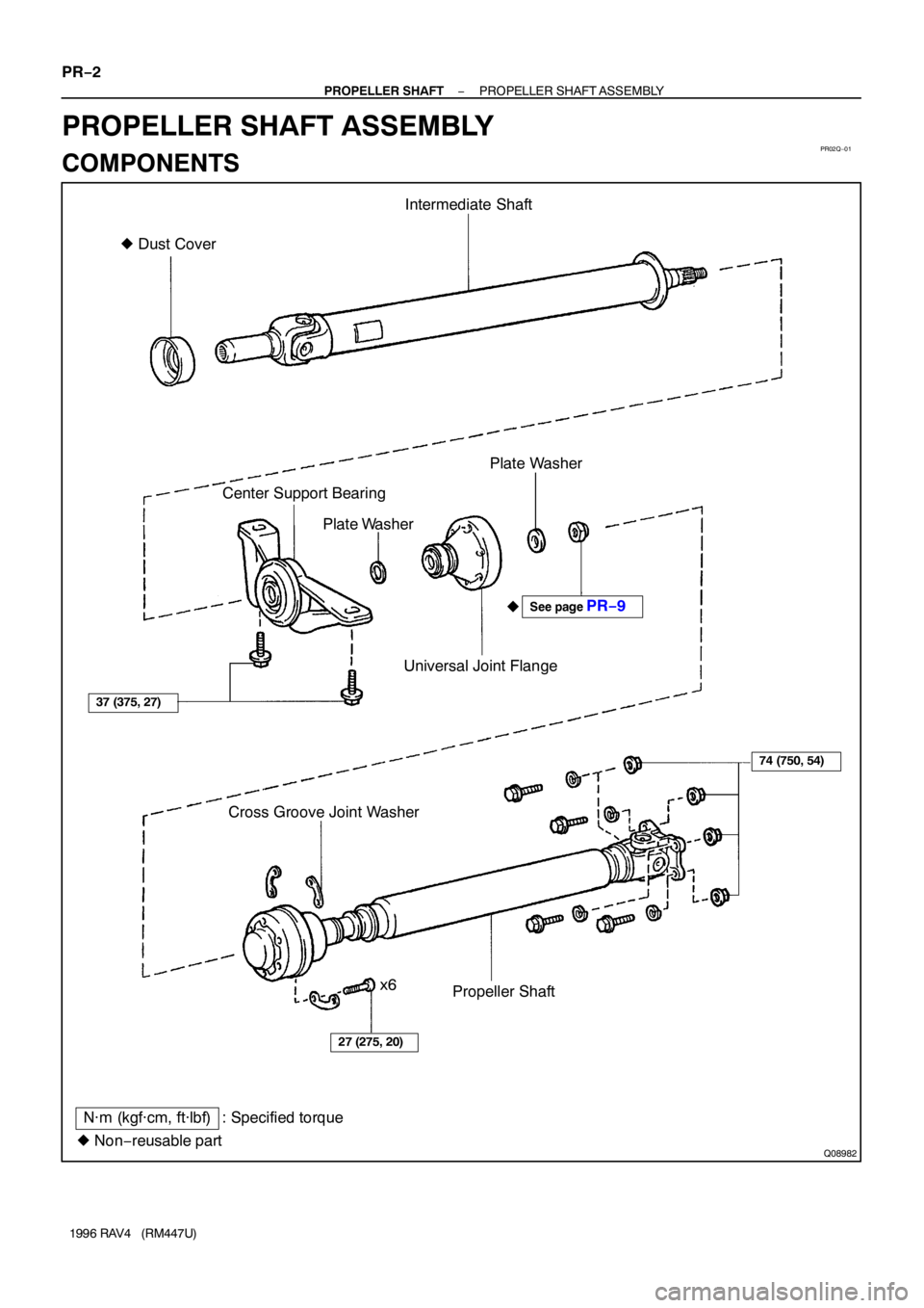
� Dust CoverIntermediate Shaft
Plate Washer
Center Support Bearing
Plate Washer
Universal Joint Flange
Cross Groove Joint Washer
Propeller Shaft
N·m (kgf·cm, ft·lbf) : Specified torque
� Non−reusable partx6
27 (275, 20)
74 (750, 54)
�
37 (375, 27)
See page PR−9 PR−2
− PROPELLER SHAFTPROPELLER SHAFT ASSEMBLY
1996 RAV4 (RM447U)
PROPELLER SHAFT ASSEMBLY
COMPONENTS
Page 1100 of 1354

REASSEMBLY
1. INSTALL CENTER SUPPORT BEARING
(a) Set the center support bearing on the")
Q05879
Rear
PR07R−01
Q06110
Matchmarks
PR−8
− PROPELLER SHAFTPROPELLER SHAFT ASSEMBLY
1996 RAV4 (RM447U)
REASSEMBLY
1. INSTALL CENTER SUPPORT BEARING
(a) Set the center support bearing on the intermediate shaft
as shown.
(b) Install the plate washer to the intermediate shaft.
(c) Align the matchmarks on the flange and shaft and place
the flange on the shaft.
(d) Using a vise to hold the flange, press the bearing into
position by tightening down a new nut and washer.
Torque: 181 N·m (1,850 kgf·cm, 134 ft·lbf)
(e) Loosen the nut.
(f) Torque the nut again.
Torque: 69 N·m (700 kgf·cm, 51 ft·lbf)
(g) Using a hammer and chisel, stake the nut.
2. INSTALL JOINT END COVER
(a) Align the matchmarks and install the universal joint flange
to the cross groove joint.
(b) Tighten the 6 bolts and 3 washers to press the joint end
cover.
HINT:
Tighten the bolts gradually and equally to prevent damaging the
end cover.
(c) Remove the 6 bolts and 3 washers and separate the uni-
versal joint flange from the cross groove joint.
3. INSPECT CROSS GROOVE JOINT (See page
PR−6)
4. CONNECT FRONT PROPELLER SHAFT WITH REAR
PROPELLER SHAFT
Using a hexagon wrench, tighten the 6 bolts and 3 washers
temporarily.
HINT:
Put a piece of cloth or an equivalent into the inside of the univer-
sal joint cover.
Page 1101 of 1354

Q06145
11.5 − 13.5 mm
(0.453 − 0.536 in.)
− PROPELLER SHAFTPROPELLER SHAFT ASSEMBLY
PR−9
1996 RAV4 (RM447U)
INSTALLATION
1. INSTALL I")
PR07S−01
Q05756
65.5 − 70.5 mm
(2.579 − 2.776 in.)
Q06145
11.5 − 13.5 mm
(0.453 − 0.536 in.)
− PROPELLER SHAFTPROPELLER SHAFT ASSEMBLY
PR−9
1996 RAV4 (RM447U)
INSTALLATION
1. INSTALL INTERMEDIATE SHAFT
(a) Remove SST from the transfer.
(b) Insert the yoke into the transfer.
2. INSTALL CENTER SUPPORT BEARING TEMPORARI-
LY
3. INSTALL PROPELLER SHAFT
(a) Align the matchmarks on the flanges and connect the
shaft with the 4 bolts, washers and nuts.
(b) Torque the bolts and nuts.
Torque: 74 N·m (750 kgf·cm, 54 ft·lbf)
4. TIGHTEN CROSS GROOVE JOINT SET BOLT
(a) Depress the brake pedal and hold it.
(b) Using a hexagon wrench, tighten the cross groove joint
set bolts.
Torque: 27 N·m (275 kgf·cm, 20 ft·lbf)
5. INSTALL CENTER SUPPORT BEARING
(a) With the vehicle in the unladen condition, adjust the di-
mension between the rear side of cover and the shaft, as
shown in the illustration.
(b) With the same condition, adjust the dimension between
the rear side of center bearing housing and the rear side
of cushion at 11.5 − 13.5 mm (0.4528 − 0.5315 in.), as
shown in the illustration below, then torque the bolts.
Torque: 37 N·m (375 kgf·cm, 27 ft·lbf)
(c) Check that the center line of the bracket is at right angles
at the shaft axial direction.

MX−91
1996 RAV4 (RM447U)
(c) Install the mounting case left side bearing.
Using SST and a press, install a new left side bearing.
SST 09316")

MX−97
1996 RAV4 (RM447U)
(d) Install and torque the 4 bolts.
Torque: 25 N·m (260 kgf·cm, 19 ft·lbf)
20. INSTALL DYNAMIC DAMPER
Install the dynamic damper and")