Page 1310 of 1354

SR0FY−01
W01200
Micrometer
Caliper
Gauge
Front Housing
Vane Pump Shaft Bushing
N00372
Height
LengthThickness
R10282Feeler Gauge
R13897
Inscribed Mark
SR−36
− STEERINGPOWER STEERING VANE PUMP
1996 RAV4 (RM447U)
INSPECTION
NOTICE:
When using a vise, do not overtighten it.
1. MEASURE OIL CLEARANCE BETWEEN VANE PUMP
SHAFT AND BUSHING
Using a micrometer and a caliper gauge, measure the oil clear-
ance.
Standard clearance:
0.03 − 0.05 mm (0.0012 − 0.0020 in.)
Maximum clearance: 0.07 mm (0.0028 in.)
If it is more than the maximum, replace the front housing and
vane pump shaft.
2. INSPECT VANE PUMP ROTOR AND VANE PLATES
(a) Using a micrometer, measure the height, thickness and
length of the 10 plates.
Minimum height: 8.1 mm (0.319 in.)
Minimum thickness: 1.797 mm (0.0707 in.)
Minimum length: 14.988 mm (0.59008 in.)
(b) Using a feeler gauge, measure the clearance between
the rotor groove and plate.
Maximum clearance: 0.03 mm (0.0012 in.)
If it is more than the maximum, replace the plate and/or rotor
with one having the same mark stamped on the cam ring.
Inscribed mark: 1, 2, 3, 4 or None
Page 1311 of 1354
R10970
W01133
Compressed Air
R10971
A
− STEERINGPOWER STEERING VANE PUMP
SR−37
1996 RAV4 (RM447U)
HINT:
There are 5 vane lengths with the following rotor and cam ring
marks:
Rotor and
cam ring markVane plate
part numberVane plate length mm
(in.)
None44345−1201014.996−14.998
(0.59039−0.59047)
144345−1202014.994−14.996
(0.59032−0.59039)
244345−1203014.992−14.994
(0.59024−0.59032)
344345−1204014.990−14.992
(0.59016−0.59024)
444345−1205014.988−14.990
(0.59008−0.59016)
3. INSPECT FLOW CONTROL VALVE
(a) Coat the flow control valve with power steering fluid and
check that it falls smoothly into the valve hole by its own
weight.
(b) Check the valve for leakage. Close one of the holes and
apply 392−490 kPa (4−5 kgf/cm
2, 57−71 psi) of com-
pressed air into the opposite side, and confirm that air
does not come out from the end hole.
If necessary, replace the valve with one having the same letter
as inscribed on the front housing.
Inscribed mark: A, B, C, D, E or F
Page 1312 of 1354
R08702
Calipers
W01131
Vinyl Tape
W01130
Press
SST
Oil SealSST SR−38
− STEERINGPOWER STEERING VANE PUMP
1996 RAV4 (RM447U)
4. INSPECT SPRING
Using calipers, measure the free length of the spring.
Minimum free length: 36.0 mm (1.42 in.)
If it is not within the specification, replace the spring.
5. IF NECESSARY, REPLACE OIL SEAL
(a) Using a screwdriver with vinyl tape wound around its tip,
remove the oil seal.
NOTICE:
Be careful not to damage the bushing of the front housing.
(b) Coat a new oil seal lip with power steering fluid.
(c) Using SST, press in the oil seal.
SST 09950−60010 (09951−00240),
09950−70010 (09951−07100)
NOTICE:
Make sure to install the oil seal facing the correct direction.
Page 1313 of 1354

SR0FZ−01
R11274
Inscribed Mark
W01172
Longer Straight Pin
Vinyl Tape
Hole
− STEERINGPOWER STEERING VANE PUMP
SR−39
1996 RAV4 (RM447U)
REASSEMBLY
NOTICE:
When using a vise, do not overtighten it.
1. COAT WITH POWER STEERING FLUID
(See page SR−31)
2. INSTALL LONGER STRAIGHT PIN
Using a plastic hammer, tap in a new pin to the front housing.
NOTICE:
Be careful not to damage the pin.
3. INSTALL SHORTER STRAIGHT PIN
Install a new pin to the side front plate.
NOTICE:
Be careful not to damage the pin.
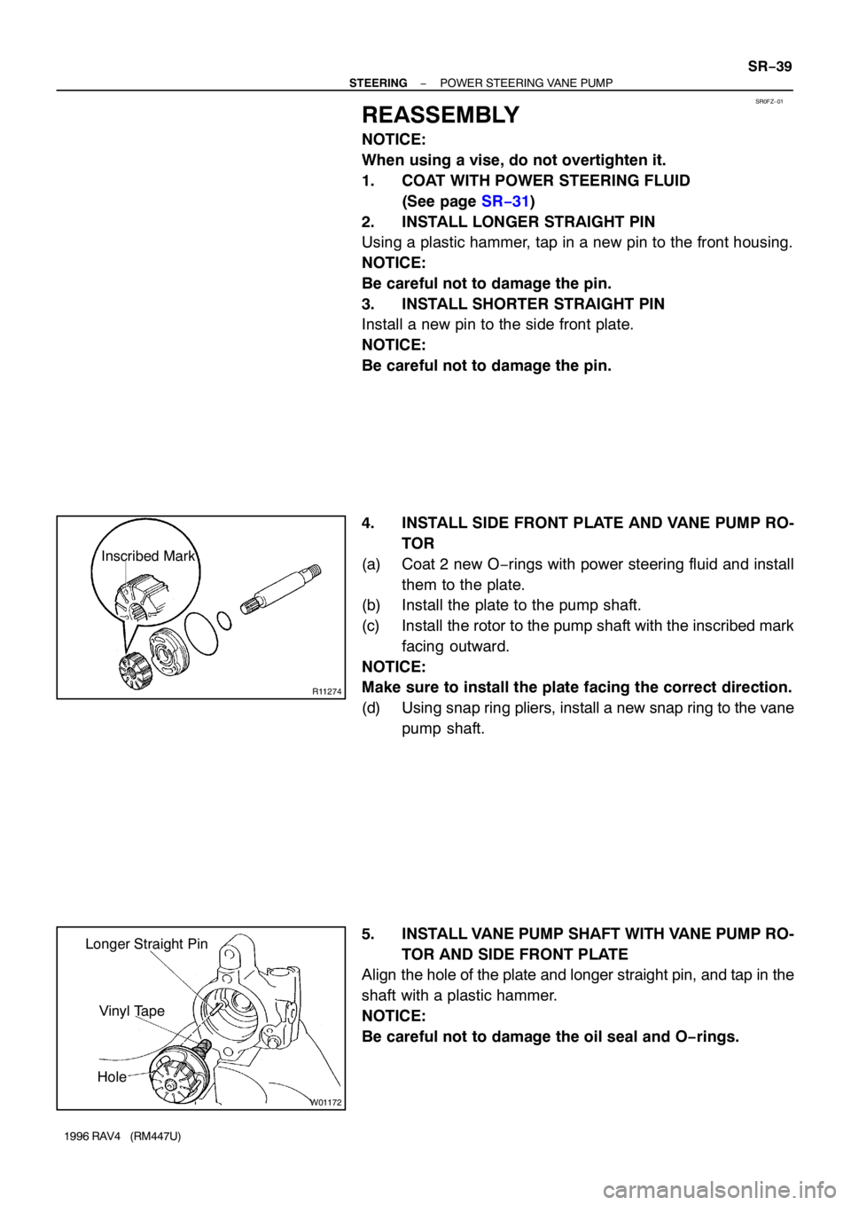
4. INSTALL SIDE FRONT PLATE AND VANE PUMP RO-
TOR
(a) Coat 2 new O−rings with power steering fluid and install
them to the plate.
(b) Install the plate to the pump shaft.
(c) Install the rotor to the pump shaft with the inscribed mark
facing outward.
NOTICE:
Make sure to install the plate facing the correct direction.
(d) Using snap ring pliers, install a new snap ring to the vane
pump shaft.
5. INSTALL VANE PUMP SHAFT WITH VANE PUMP RO-
TOR AND SIDE FRONT PLATE
Align the hole of the plate and longer straight pin, and tap in the
shaft with a plastic hammer.
NOTICE:
Be careful not to damage the oil seal and O−rings.
Page 1314 of 1354

R11231
Inscribed Mark
R10976
Round End
W01173
Wave Washer
R10968
SR−40
− STEERINGPOWER STEERING VANE PUMP
1996 RAV4 (RM447U)
6. INSTALL CAM RING
Align the holes of the cam ring and 2 straight pins and install the
ring with the inscribed mark facing outward.
7. INSTALL VANE PLATES
Install the 10 plates with the round end facing outward.
8. INSTALL SIDE REAR PLATE
(a) Coat a new O−ring with power steering fluid and install it
to the plate.
(b) Align the holes of the plate and 2 straight pins, and install
the plate.
9. INSTALL WAVE WASHER
Install the washer so that its protrusions fit into the slots in the
side rear plate.
10. INSTALL REAR HOUSING
(a) Coat a new O−ring with power steering fluid and install it
to the housing.
(b) Using a plastic hammer, tap in the housing to the front
housing.
NOTICE:
Be careful not to damage the O−ring.
(c) Install a new snap ring.
11. INSTALL FLOW CONTROL SPRING SEAT
(a) Coat a new O−ring with power steering fluid and install it
to the flow control spring seat.
(b) Install the 2−3 threads of the bolt to the spring seat.
(c) Using pliers, install the spring seat to the front housing.
NOTICE:
�Be careful not to damage the O−ring.
�Make sure to install the seat facing the correct direc-
tion.
Page 1315 of 1354

R10995
2.5°
R10992
SST
− STEERINGPOWER STEERING VANE PUMP
SR−41
1996 RAV4 (RM447U)
(d) Using snap ring pliers, install a new snap ring.
12. INSTALL SPRING AND FLOW CONTROL VALVE
Install the valve facing the correct direction
(See page SR−31).
13. INSTALL PRESSURE PORT UNION
(a) Coat a new O−ring with power steering fluid and install it
to the union.
(b) Torque the union.
Torque: 69 N·m (700 kgf·cm, 51 ft·lbf)
14. INSTALL SUCTION PORT UNION
(a) Coat a new O−ring with power steering fluid and install it
to the union.
(b) Install the O−ring to the union.
(c) Install the union with the bolt.
Torque: 13 N·m (130 kgf·cm, 9 ft·lbf)
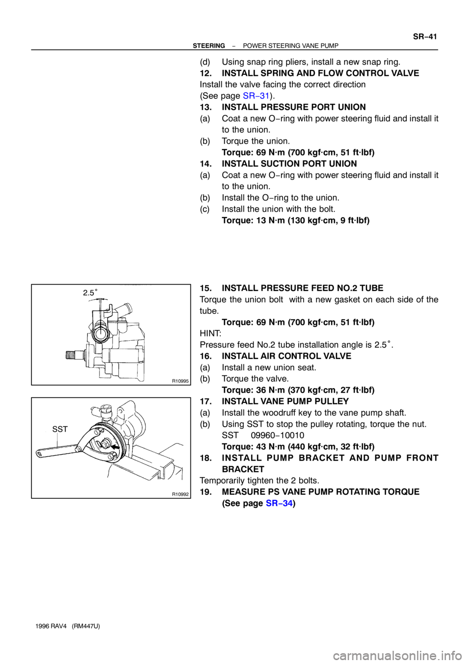
15. INSTALL PRESSURE FEED NO.2 TUBE
Torque the union bolt with a new gasket on each side of the
tube.
Torque: 69 N·m (700 kgf·cm, 51 ft·lbf)
HINT:
Pressure feed No.2 tube installation angle is 2.5°.
16. INSTALL AIR CONTROL VALVE
(a) Install a new union seat.
(b) Torque the valve.
Torque: 36 N·m (370 kgf·cm, 27 ft·lbf)
17. INSTALL VANE PUMP PULLEY
(a) Install the woodruff key to the vane pump shaft.
(b) Using SST to stop the pulley rotating, torque the nut.
SST 09960−10010
Torque: 43 N·m (440 kgf·cm, 32 ft·lbf)
18. INSTALL PUMP BRACKET AND PUMP FRONT
BRACKET
Temporarily tighten the 2 bolts.
19. MEASURE PS VANE PUMP ROTATING TORQUE
(See page SR−34)
Page 1316 of 1354

SR0G0−03
W01943
Stopper
Pressure Feed
Tube
R10966
W01119
SST
Fulcrum Length
R10981
SR−42
− STEERINGPOWER STEERING VANE PUMP
1996 RAV4 (RM447U)
INSTALLATION
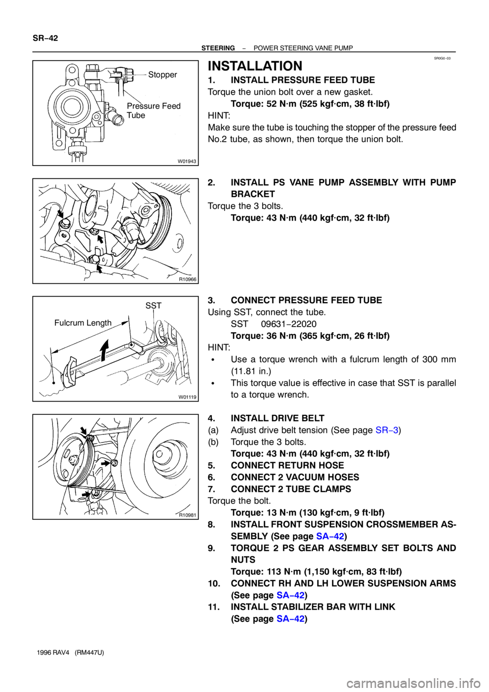
1. INSTALL PRESSURE FEED TUBE
Torque the union bolt over a new gasket.
Torque: 52 N·m (525 kgf·cm, 38 ft·lbf)
HINT:
Make sure the tube is touching the stopper of the pressure feed
No.2 tube, as shown, then torque the union bolt.
2. INSTALL PS VANE PUMP ASSEMBLY WITH PUMP
BRACKET
Torque the 3 bolts.
Torque: 43 N·m (440 kgf·cm, 32 ft·lbf)
3. CONNECT PRESSURE FEED TUBE
Using SST, connect the tube.
SST 09631−22020
Torque: 36 N·m (365 kgf·cm, 26 ft·lbf)
HINT:
�Use a torque wrench with a fulcrum length of 300 mm
(11.81 in.)
�This torque value is effective in case that SST is parallel
to a torque wrench.
4. INSTALL DRIVE BELT
(a) Adjust drive belt tension (See page SR−3)
(b) Torque the 3 bolts.
Torque: 43 N·m (440 kgf·cm, 32 ft·lbf)
5. CONNECT RETURN HOSE
6. CONNECT 2 VACUUM HOSES
7. CONNECT 2 TUBE CLAMPS
Torque the bolt.
Torque: 13 N·m (130 kgf·cm, 9 ft·lbf)
8. INSTALL FRONT SUSPENSION CROSSMEMBER AS-
SEMBLY (See page SA−42)
9. TORQUE 2 PS GEAR ASSEMBLY SET BOLTS AND
NUTS
Torque: 113 N·m (1,150 kgf·cm, 83 ft·lbf)
10. CONNECT RH AND LH LOWER SUSPENSION ARMS
(See page SA−42)
11. INSTALL STABILIZER BAR WITH LINK
(See page SA−42)
Page 1317 of 1354
− STEERINGPOWER STEERING VANE PUMP
SR−43
1996 RAV4 (RM447U)
12. INSTALL FRONT EXHAUST PIPE
(a) Torque the 2 bolts with a new gasket.
Torque: 48 N·m (490 kgf·cm, 35 ft·lbf)
(b) Torque 3 new nuts with a new gasket.
Torque: 62 N·m (630 kgf·cm, 46 ft·lbf)
13. INSTALL RH AND LH ENGINE UNDER COVERS
Tighten the 13 bolts.
14. BLEED POWER STEERING SYSTEM
(See page SR−4)