Page 590 of 1354
W01939
W
1D
1K
21D
1F 74
4 2
9
1
6
W1E
1A
IB2 A16
A17
A1713 14
211 213
*
2*1
1 6 6 13 12 B−Y
B−YB−Y
GND
GND IG1
W−B
ALT F7
Fusible
Link
Block
BatteryJ/B No. 1
J/B No. 1ECU−IG IG Switch
J/B No. 1
ABS ECU
R/B No. 2
A17
A17 A17 2
W−B
EB
B−Y
*
1: 2WD models
*2: 4WD models B−Y
AM1
W DI−270
− DIAGNOSTICSANTI−LOCK BRAKE SYSTEM
1996 RAV4 (RM447U)
DTC Always ON Malfunction in ECU
IG Power Source Circuit (2WD Models)
CIRCUIT DESCRIPTION
This is the power source for the ECU, hence the CPU, and the actuators.
DTC No.DTC Detecting ConditionTrouble Area
Always ONVoltage of ECU terminal IG1 remains at more than 17 V
�Battery
�IC regulator
�Open or short in power source circuit
�ECU
Fail safe function:
If trouble occurs in the power source circuit, the ECU cuts off current to the ABS control (solenoid) relay and
prohibits ABS control.
WIRING DIAGRAM
DI41T−02
Page 591 of 1354
− DIAGNOSTICSANTI−LOCK BRAKE SYSTEM
DI−271
1996 RAV4 (RM447U)
INSPECTION PROCEDURE
1 Is DTC output?
Check DTC on page DI−234.
YES Repair circuit indicated by code output.
NO
2 Is normal code displayed?
YES Check ABS solenoid relay. Check for short in
harness and connector between ABS solenoid
relay and DLC1 (See page IN−30).
NO
3 Is ABS warning light go off?
YES Check for open or short in harness and connec-
tor between ECU−IG Fuse and ECU (See page
IN−30).
NO
4 Check battery positive voltage.
PREPARATION:
Start the engine.
CHECK:
Check the battery positive voltage.
OK:
Voltage: 10 − 16 V
NG Check and repair charging system.
OK
Page 596 of 1354

R14139
1 2
5 6 3A8
A9
R14140
(−)
(+)1 2
5
6
3A8
A9
R14144
(+) (−)4 5 A8
A9
DI−276
− DIAGNOSTICSANTI−LOCK BRAKE SYSTEM
1996 RAV4 (RM447U)
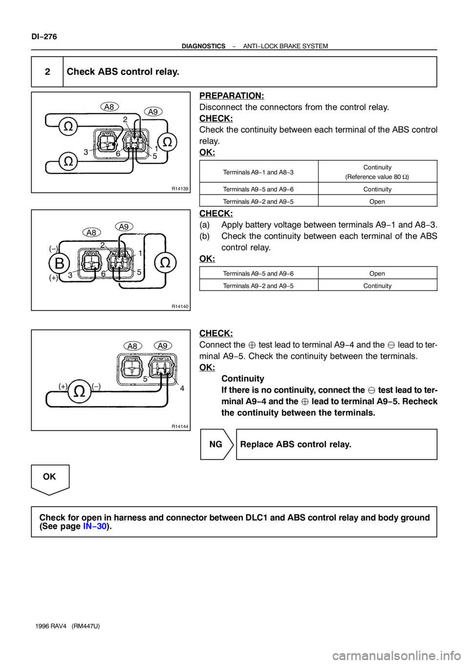
2 Check ABS control relay.
PREPARATION:
Disconnect the connectors from the control relay.
CHECK:
Check the continuity between each terminal of the ABS control
relay.
OK:
Terminals A9−1 and A8−3Continuity
(Reference value 80 Ω)
Terminals A9−5 and A9−6Continuity
Terminals A9−2 and A9−5Open
CHECK:
(a) Apply battery voltage between terminals A9−1 and A8−3.
(b) Check the continuity between each terminal of the ABS
control relay.
OK:
Terminals A9−5 and A9−6Open
Terminals A9−2 and A9−5Continuity
CHECK:
Connect the � test lead to terminal A9−4 and the � lead to ter-
minal A9−5. Check the continuity between the terminals.
OK:
Continuity
If there is no continuity, connect the � test lead to ter-
minal A9−4 and the � lead to terminal A9−5. Recheck
the continuity between the terminals.
NG Replace ABS control relay.
OK
Check for open in harness and connector between DLC1 and ABS control relay and body ground
(See page IN−30).
Page 609 of 1354

DI42J−02
DI−332
− DIAGNOSTICSCRUISE CONTROL SYSTEM
1996 RAV4 (RM447U)
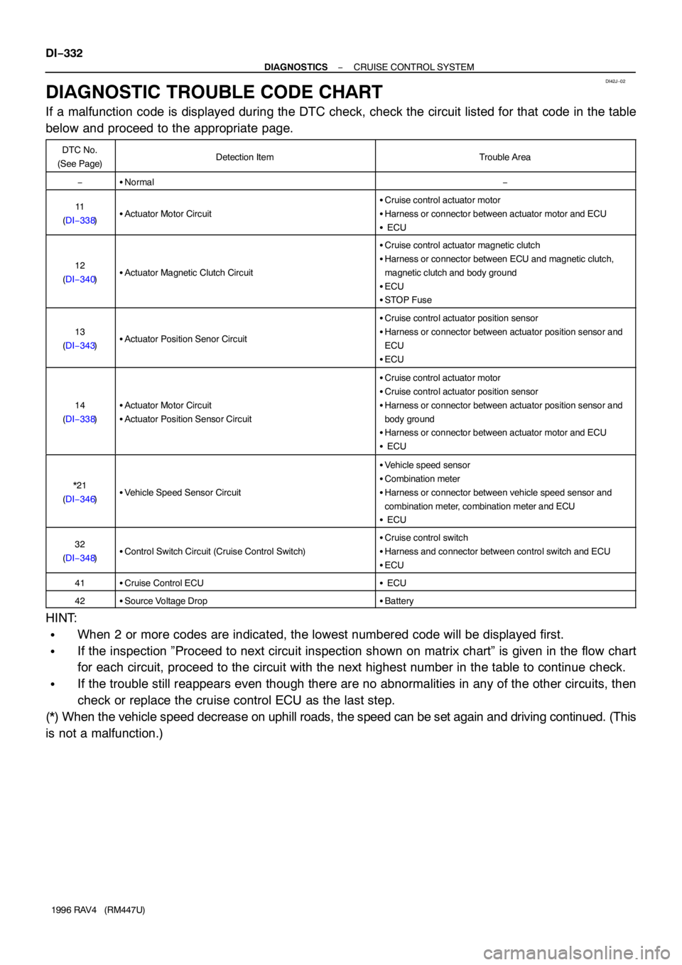
DIAGNOSTIC TROUBLE CODE CHART
If a malfunction code is displayed during the DTC check, check the circuit listed for that code in the table
below and proceed to the appropriate page.
DTC No.
(See Page)Detection ItemTrouble Area
−�Normal−
11
(DI−338)�Actuator Motor Circuit
�Cruise control actuator motor
�Harness or connector between actuator motor and ECU
� ECU
12
(DI−340)�Actuator Magnetic Clutch Circuit
�Cruise control actuator magnetic clutch
�Harness or connector between ECU and magnetic clutch,
magnetic clutch and body ground
�ECU
�STOP Fuse
13
(DI−343)�Actuator Position Senor Circuit
�Cruise control actuator position sensor
�Harness or connector between actuator position sensor and
ECU
�ECU
14
(DI−338)�Actuator Motor Circuit
�Actuator Position Sensor Circuit
�Cruise control actuator motor
�Cruise control actuator position sensor
�Harness or connector between actuator position sensor and
body ground
�Harness or connector between actuator motor and ECU
� ECU
*21
(DI−346)�Vehicle Speed Sensor Circuit
�Vehicle speed sensor
�Combination meter
�Harness or connector between vehicle speed sensor and
combination meter, combination meter and ECU
� ECU
32
(DI−348)�Control Switch Circuit (Cruise Control Switch)
�Cruise control switch
�Harness and connector between control switch and ECU
�ECU
41�Cruise Control ECU� ECU
42�Source Voltage Drop�Battery
HINT:
�When 2 or more codes are indicated, the lowest numbered code will be displayed first.
�If the inspection ”Proceed to next circuit inspection shown on matrix chart” is given in the flow chart
for each circuit, proceed to the circuit with the next highest number in the table to continue check.
�If the trouble still reappears even though there are no abnormalities in any of the other circuits, then
check or replace the cruise control ECU as the last step.
(*) When the vehicle speed decrease on uphill roads, the speed can be set again and driving continued. (This
is not a malfunction.)
Page 616 of 1354

N14648N17426I09111
Acceleration
SideDeceleration
Side
Control
Plate (+)5
4
(−)
− DIAGNOSTICSCRUISE CONTROL SYSTEM
DI−339
1996 RAV4 (RM447U)
INSPECTION PROCEDURE
1 Check actuator motor.
PREPARATION:
(a) Remove cruise control actuator.
(b) Disconnect actuator connector.
CHECK:
(a) Connect positive + lead to terminal 5 and negative − lead
to terminal 4 of actuator connector (Magnetic clutch ON).
NOTICE:
Do not connect the high tension cables to the wrong bat-
tery terminal.
You will damage the cruise control actuator.
(b) When battery positive voltage is applied to each terminal
of actuator connector, check that the control plate moves
smoothly without hesitating.
Moving directionTerminal No. to connect
Acceleration sidePositive + − 6Negative − − 7
Deceleration sidePositive + − 7Negative − − 6
(c) With the motor rotating as in 2., check that the motor is
stopped by limit switches when the control plate moves to
fully opened or fully closed position.
NG Replace actuator assembly.
OK
2 Check harness and connector between cruise control ECU and actuator motor
(See page IN−30).
NG Repair or replace harness or connector.
OK
Proceed to next circuit inspection shown on matrix chart (See page DI−336).
However, when DTC 11, 14 is displayed, check and replace cruise control ECU.
Page 628 of 1354
N17898
Ignition
SwitchSTOP FuseStop Light
SwitchCruise Control
ECU
STP−
L
L−
GNDL5
47 211
1F1I
IB2
IB2 16
L−BG−B10
2616 1
3 42
R−W R−WJ/B No.1
R−Y
L−BG−W
R−Y
10 A
Cruise Control
Actuator
− DIAGNOSTICSCRUISE CONTROL SYSTEM
DI−351
1996 RAV4 (RM447U)
Stop Light Switch Circuit
CIRCUIT DESCRIPTION
When the brake is on, battery positive voltage normally applies through the stop fuse and stop light switch
to terminal STP− of the ECU, and the ECU turns the cruise control off.
A fail−safe function is provided so that cancel functions normally, even if there is a malfunction in the stop
light signal circuit.
If the harness connected to terminal STP− has an open, terminal STP− will have battery positive voltage and
the cruise control will be turned off, also SET not occurring.
Also, when the brake is on, the magnetic clutch is cut electrically by the stop light switch, turning the cruise
control off. (See page DI−338 for operation of the magnetic clutch)
WIRING DIAGRAM
DI42S−02
Page 643 of 1354
N21699
Ignition
Switch
1D 1F1E
1A
1D 1K9
22 4 247
466
B 14
BB
Junction
Connector W−BW−B
13
GND W
IG
Fuse Block
ALT
100 A
BatteryJ/B No.1R/B No.2 J/B No.1
J/B No.1Cruise Control
ECU
Fuse Block
ECU−IG
7.5 AB−Y B−Y
W
B−Y
AM1
40 AW DI−366
− DIAGNOSTICSCRUISE CONTROL SYSTEM
1996 RAV4 (RM447U)
ECU Power Source Circuit
CIRCUIT DESCRIPTION
The ECU power source supplies power to the actuator and sensors, etc., Terminal GND and the cruise con-
trol ECU case are grounded.
WIRING DIAGRAM
DI42X−02
Page 645 of 1354
N14704BE6053I09123
LOCK
GND
DI−368
− DIAGNOSTICSCRUISE CONTROL SYSTEM
1996 RAV4 (RM447U)
3 Check continuity between terminal GND of ECU connector and body ground .
CHECK:
Measure resistance between terminal GND of cruise control
ECU connector and body ground.
OK:
Resistance: 1 Ω or less
NG Repair or replace harness or connector.
OK
Check and repair harness and connector be-
tween battery and ECU.