Page 405 of 1399

P03788
CORRECT WRONG
Clearance
Z00038
Nippondenso Borroughs
−
CHARGING CHARGING SYSTEM
CH−3
1996 LAND CRUISER (RM451U)
(b) Check the fusible link and fuses for continuity.
Fusible link
MAIN 2.0 A
AM1 1.25 B
AM2 0.3 P
H−fuseAM1 50 A
FuseIGN 7.5 A
GAUGE 15 A
3. INSPECT DRIVE BELTS
(a) Visually check the drive belt for cracks, oiliness or wear.
Check that the belt does not touch the bottom of the pulley
groove.
If necessary, replace the drive belts as a set.
(b) Using a belt tension gauge, measure the belt tension. Belt tension gauge:
Nippondenso BTG−20 (95506 −00020)
Borroughts No. BT−33−73F
Drive belt tension:
New belt400 − 580 N (41.0 − 59.1 kgf, 90.4 − 130.2 lbf)
Used belt200 − 390 N (20.4 − 40.0 kgf, 45.0 − 88.2 lbf)
If the belt tension is not as specified, adjust it.
HINT:
�”New belt” refers to a belt which has been used less than
5 minutes on a running engine.
�”Used belt” refers to a belt which has been used on a run-
ning engine for 5 minutes or more.
�After installing a new belt, run the engine for about 5 min-
utes and recheck the belt tension.
4. VISUALLY CHECK GENERATOR WIRING AND LIS- TEN FOR ABNORMAL NOISES
(a) Check that the wiring is in good condition.
(b) Check that there is no abnormal noise from the generator
while the engine is running.
5. INSPECT DISCHARGE WARNING LIGHT CIRCUIT
(a) Turn the ignition switch ”ON”. Check that the discharge warning light comes on.
(b) Start the engine. Check that the light goes off.
Brought to you by BirfMark
Brought to you by BirfMark
Version 1.11 - 03/16/2010
Page 410 of 1399
CH0EP−01
CH−8
−
CHARGING GENERATOR
1996 LAND CRUISER (RM451U)
REMOVAL
1. REMOVE BATTERY AND BATTERY TRAY
2. DISCONNECT POWER STEERING (PS) RESERVOIR TANK
3. REMOVE DRIVE BELTS
(a) Loosen the lock bolt, pivot bolt and adjusting bolt.
(b) Remove the 2 drive belts.
4. REMOVE GENERATOR
(a) Disconnect the generator connector.
(b) Remove the rubber cap and nut, and disconnect the gen-
erator wire.
(c) Disconnect the generator wire clamp from the generator.
(d) Remove the lock bolt, bolt, nut and drive belt adjusting bar.
(e) Remove the pivot bolt and generator.
Brought to you by BirfMark
Brought to you by BirfMark
Version 1.11 - 03/16/2010
Page 413 of 1399
P08243
SST (C)Turn
SST (A)
P03794
−
CHARGING GENERATOR
CH−11
1996 LAND CRUISER (RM451U)
(e) To loosen the pulley nut, turn SST (A) in the direction
shown in the illustration.
NOTICE:
To prevent damage to the rotor shaft, do not loosen the
pulley nut more than one −half of a turn.
(f) Remove the generator from SST (C).
(g) Turn SST (B) and remove SST (A and B).
(h) Remove the pulley nut and pulley.
6. REMOVE RECTIFIER END FRAME
(a) Remove the 4 nuts.
(b) Using SST, remove the rectifier end frame. SST 09286−46011
(c) Remove the generator washer.
7. REMOVE ROTOR FROM DRIVE END FRAME
Brought to you by BirfMark
Brought to you by BirfMark
Version 1.11 - 03/16/2010
Page 414 of 1399

CH0784
ContinuityOhmmeter
CH0HP
−01
CH0783
No Continuity Ohmmeter
CH0192
P00484
Continuity
Ohmmeter
P00482
No Continuity
Ohmmeter
CH−12
−
CHARGING GENERATOR
1996 LAND CRUISER (RM451U)
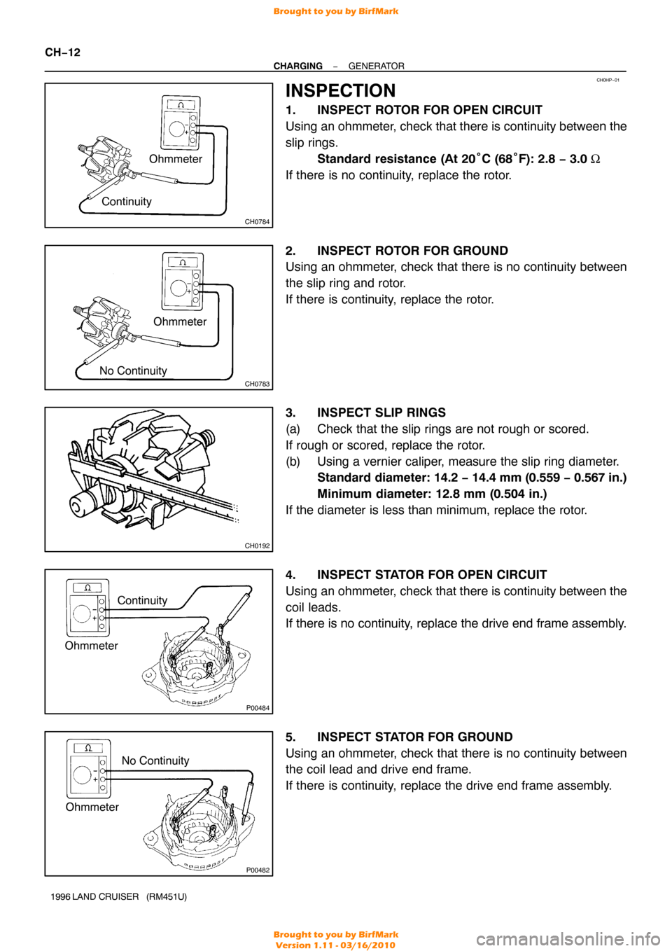
INSPECTION
1. INSPECT ROTOR FOR OPEN CIRCUIT
Using an ohmmeter, check that there is continuity between the
slip rings.
Standard resistance (At 20 °C (68° F): 2.8 − 3.0 Ω
If there is no continuity, replace the rotor.
2. INSPECT ROTOR FOR GROUND
Using an ohmmeter, check that there is no continuity between
the slip ring and rotor.
If there is continuity, replace the rotor.
3. INSPECT SLIP RINGS
(a) Check that the slip rings are not rough or scored.
If rough or scored, replace the rotor.
(b) Using a vernier caliper, measure the slip ring diameter. Standard diameter: 14.2 − 14.4 mm (0.559 − 0.567 in.)
Minimum diameter: 12.8 mm (0.504 in.)
If the diameter is less than minimum, replace the rotor.
4. INSPECT STATOR FOR OPEN CIRCUIT
Using an ohmmeter, check that there is continuity between the
coil leads.
If there is no continuity, replace the drive end frame assembly.
5. INSPECT STATOR FOR GROUND
Using an ohmmeter, check that there is no continuity between
the coil lead and drive end frame.
If there is continuity, replace the drive end frame assembly.
Brought to you by BirfMark
Brought to you by BirfMark
Version 1.11 - 03/16/2010
Page 418 of 1399
P03802
CH06M−03
P03794
P03807
Hold SST (A)
SST (B)
Turn
P08242
SST (C)
CH−16
−
CHARGING GENERATOR
1996 LAND CRUISER (RM451U)
REASSEMBLY
1. PLACE RECTIFIER END FRAME ON PULLEY
2. INSTALL ROTOR TO DRIVE END FRAME
3. INSTALL RECTIFIER END FRAME
(a) Place the generator washer on the rotor.
(b) Using a 29 mm socket wrench and press, slowly press in
the rectifier end frame.
(c) Install the 4 nuts. Torque: 4.5 N·m (46 kgf·cm, 40 in.·lbf)
4. INSTALL PULLEY
(a) Install the pulley to the rotor shaft by tightening the pulley
nut by hand.
(b) Hold SST (A) with a torque wrench, and tighten SST (B)
clockwise to the specified torque.
SST 09820−63010
Torque: 39 N·m (400 kgf·cm, 29 ft·lbf)
(c) Check that SST (A) is secured to the pulley shaft.
(d) Mount SST (C) in a vise.
(e) Install the generator to SST (C).
Brought to you by BirfMark
Brought to you by BirfMark
Version 1.11 - 03/16/2010
Page 421 of 1399
CH06N−03
−
CHARGING GENERATOR
CH−19
1996 LAND CRUISER (RM451U)
INSTALLATION
1. INSTALL GENERATOR
(a) Mount generator on the generator bracket with the pivot
bolt. Do not tighten the bolt yet.
(b) Install the drive belt adjusting bar with the bolt and nut. Torque: 21 N·m (210 kgf·cm, 15 ft·lbf)
(c) Temporarily install the lock bolt.
(d) Connect the generator connector.
(e) Connect the generator wire with the nut and rubber cap.
(f) Connect the generator wire clamp to the generator.
2. INSTALL DRIVE BELTS
(a) Install the drive belts.
(b) Adjust the drive belt with the adjusting bolt (See page
CH−2 ).
(c) Tighten the pivot and adjusting lock bolts. Torque:
Pivot bolt: 59 N·m (600 kgf·cm, 43 ft·lbf)
Lock bolt: 21 N·m (210 kgf·cm, 15 ft·lbf)
3. CONNECT POWER STEERING (PS) RESERVOIR TANK
4. INSTALL BATTERY TRAY AND BATTERY
5. PERFORM ON−VEHICLE INSPECTION (See page CH−2 )
Brought to you by BirfMark
Brought to you by BirfMark
Version 1.11 - 03/16/2010
Page 425 of 1399
CO112−01
CO−4
−
COOLING WATER PUMP
1996 LAND CRUISER (RM451U)
REMOVAL
1. DRAIN ENGINE COOLANT
2. DISCONNECT NO.3 WATER BYPASS HOSE
3. DISCONNECT RADIATOR INLET HOSE
4. REMOVE DRIVE BELTS, FAN WITH FLUID COU- PLING, WATER PUMP PULLEY AND FAN SHROUD
(a) Stretch the belts and loosen the water pump pulley mounting nuts.
(b) Loosen the lock, pivot and adjusting bolts of the genera- tor, and remove the drive belts.
(c) Disconnect the oil cooler hose from the clamp on the fan shroud.
(d) Remove the 2 bolts holding the fan shroud to the radiator.
(e) Remove the 4 water pump pulley mounting nuts.
(f) Pull out the fan with fluid coupling, water pump pulley and
fan shroud.
(g) Remove the fan from the fluid coupling.
5. REMOVE WATER PUMP
Remove the 4 bolts, 2 nuts, water pump and gasket.
Brought to you by BirfMark
Brought to you by BirfMark
Version 1.11 - 03/16/2010
Page 427 of 1399

CO114−02
CO−6
−
COOLING WATER PUMP
1996 LAND CRUISER (RM451U)
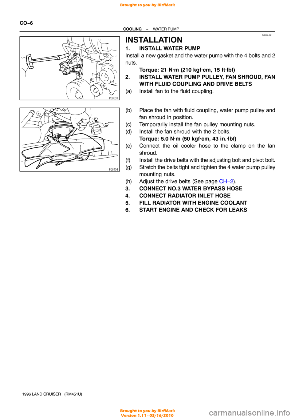
INSTALLATION
1. INSTALL WATER PUMP
Install a new gasket and the water pump with the 4 bolts and 2
nuts. Torque: 21 N·m (210 kgf·cm, 15 ft·lbf)
2. INSTALL WATER PUMP PULLEY, FAN SHROUD, FAN WITH FLUID COUPLING AND DRIVE BELTS
(a) Install fan to the fluid coupling.
(b) Place the fan with fluid coupling, water pump pulley and fan shroud in position.
(c) Temporarily install the fan pulley mounting nuts.
(d) Install the fan shroud with the 2 bolts. Torque: 5.0 N·m (50 kgf·cm, 43 in.·lbf)
(e) Connect the oil cooler hose to the clamp on the fan
shroud.
(f) Install the drive belts with the adjusting bolt and pivot bolt.
(g) Stretch the belts tight and tighten the 4 water pump pulley mounting nuts.
(h) Adjust the drive belts (See page CH−2 ).
3. CONNECT NO.3 WATER BYPASS HOSE
4. CONNECT RADIATOR INLET HOSE
5. FILL RADIATOR WITH ENGINE COOLANT
6. START ENGINE AND CHECK FOR LEAKS
Brought to you by BirfMark
Brought to you by BirfMark
Version 1.11 - 03/16/2010