Page 846 of 1399

14. INSTALL HEATER PIPE
Install a new gasket, the heater pipe and ground cable with the
2 bolts and 2 nuts.
Torque:
20 N·m (2")
−
ENGINE MECHANICAL CYLINDER HEAD
EM−61
1996 LAND CRUISER (RM451U)
14. INSTALL HEATER PIPE
Install a new gasket, the heater pipe and ground cable with the
2 bolts and 2 nuts.
Torque:
20 N·m (200 kgf·cm, 14 ft·lbf) for bolt:
21 N·m (210 kgf·cm, 15 ft·lbf) for nut
15. INSTALL NO. 1 AND NO. 2 EXHAUST MANIFOLDS
(a) Install 2 new gaskets, No. 1 exhaust manifold and No. 2
exhaust manifold with the 13 nuts.
Torque: 39 N·m (400 kgf·cm, 29 ft·lbf)
(b) Install the No. 1 heat insulator and No. 2 heat insulator with the 6 bolts.
Torque: 19 N·m (195 kgf·cm, 14 ft·lbf)
16. INSTALL FRONT EXHAUST PIPE
(a) Install 2 new gaskets and the front exhaust pipe with the 4 nuts.
Torque: 63 N·m (630 kgf·cm, 46 ft·lbf)
(b) Install the No. 1 support bracket with the 2 bolts. Torque: 24 N·m (240 kgf·cm, 17 ft·lbf)
(c) Connect the clamp and tighten the clamp bolt.
Torque: 19.5 N·m (195 kgf·cm, 14 ft·lbf)
(d) Connect the front exhaust pipe to the rear TWC with a new gasket, 2 bolts and 2 nuts.
Torque: 46 N·m (470 kgf·cm, 34 ft·lbf)
17. CONNECT NO. 2 WATER BYPASS PIPE
Connect the bypass pipe to the cylinder head with the 3 bolts.
Torque: 20 N·m (200 kgf·cm, 14 ft·lbf)
18. CONNECT ENGINE WIRE
(a) Place the engine wire on the intake manifold.
(b) Connect the connectors. (1) Connect the 3 injector connectors.
(2) Connect the EGR gas temp. sensor connector.
(c) Connect the clamp of the No.6 injector wire to the bracket.
(d) Connect the engine wire clamp.
(e) Connect the engine wire clamp.
(f) Connect the connectors. (1) Connect the connector for the emission control
valve set assembly.
(2) Connect the 3 injector connectors.
(g) Install the bolt holding the engine wire to the intake man- ifold.
Brought to you by BirfMark
Brought to you by BirfMark
Version 1.11 - 03/16/2010
Page 847 of 1399

(h) Connect the engine wire to the intake manifold and cylin-
der block with the 2 bolts.
(i) Connect the PNP switch connector")
EM−62
−
ENGINE MECHANICAL CYLINDER HEAD
1996 LAND CRUISER (RM451U)
(h) Connect the engine wire to the intake manifold and cylin-
der block with the 2 bolts.
(i) Connect the PNP switch connector.
(j) Connect the 2 heated oxygen sensor connectors.
(k) Connect the connectors.
(1) Connect the Knock sensor connector.
(2) Connect the oil level sensor connector.
(3) Connect the 2 connectors to tthe ransmission.
(4) Connect the starter connector.
(l) Connect the engine wire to the cylinder block with the bolt.
(m) Connect the connectors.
(1) Connect the ECT sender gauge connector.
(2) Connect the ECT cut switch connector.
(3) Connect the ECT sensor connector.
(4) Connect the knock sensor connector.
(5) Connect the crankshaft position sensor connector.
19. CONNECT FUEL INLET HOSE
Connect the fuel inlet hose to the fuel filter with 2 new gaskets
and the union bolt. Torque: 29 N·m (300 kgf·cm, 22 ft·lbf)
20. INSTALL INTAKE MANIFOLD STAY
Install the intake manifold stay with the 2 bolts. Torque: 36 N·m (360 kgf·cm, 26 ft·lbf)
21. INSTALL OIL DIPSTICKS AND GUIDES FOR ENGINE AND TRANSMISSION
(a) Install a new O−ring to the dipstick guide.
(b) Apply a light coat of engine oil on the O −ring.
(c) Push in the dipstick guide into the guide hole of the oil pan.
(d) Install the dipstick guide with the 2 bolts. Torque: 20 N·m (200 kgf·cm, 14 ft·lbf)
22. INSTALL THROTTLE BODY (See page SF−48)
23. INSTALL GENERATOR AND DRIVE BELTS (See page CH−19 )
Brought to you by BirfMark
Brought to you by BirfMark
Version 1.11 - 03/16/2010
Page 848 of 1399

24. CONNECT NO. 3 WATER BYPASS HOSE
25. CONNECT RADIATOR INLET HOSE
26. CONNECT PS RESERVOIR TANK
Connect the reservoir tank wi")
−
ENGINE MECHANICAL CYLINDER HEAD
EM−63
1996 LAND CRUISER (RM451U)
24. CONNECT NO. 3 WATER BYPASS HOSE
25. CONNECT RADIATOR INLET HOSE
26. CONNECT PS RESERVOIR TANK
Connect the reservoir tank with the 3 bolts.
Torque: 20 N·m (200 kgf·cm, 14 ft·lbf)
27. INSTALL DISTRIBUTOR (See page IG−11)
28. INSTALL NO. 2 AND NO. 3 CYLINDER HEAD COVERS
Install the head covers with the 4 bolts.
29. CONNECT HEATER VALVE AND ENGINE WIRE TO COWL PANEL
(a) Connect the heater valve with the 2 bolts.
(b) Connect the engine wire and ground strap with the 2 bolts.
30. CONNECT HEATER HOSES
31. CONNECT FUEL RETURN HOSE
32. CONNECT EVAP HOSE
33. CONNECT BRAKE BOOSTER VACUUM HOSE
34. CONNECT CONNECTOR ON INTAKE MANIFOLD TO LH FENDER APRON
35. CONNECT ENGINE GROUND STRAPS
(a) Connect the ground strap to the No. 1 engine hanger.
(b) Connect the ground strap to the air intake chamber.
36. CONNECT THROTTLE CABLE TO THROTTLE BODY
37. CONNECT ACCELERATOR CABLE TO THROTTLE
BODY
38. CONNECT CRUISE CONTROL ACTUATOR CABLE TO
THROTTLE BODY
Brought to you by BirfMark
Brought to you by BirfMark
Version 1.11 - 03/16/2010
Page 849 of 1399
EM−64
−
ENGINE MECHANICAL CYLINDER HEAD
1996 LAND CRUISER (RM451U)
39. INSTALL AIR CLEANER HOSE AND CAP
40. INSTALL BATTERY TRAY AND BATTERY
(a) Install the battery tray with the 5 bolts.
(b) Connect the ground strap with the bolt.
(c) Install the battery and hold−down clamp with the nuts.
(d) Connect the battery cables.
41. FILL RADIATOR WITH ENGINE COOLANT
42. START ENGINE AND CHECK FOR LEAKS
43. ADJUST IGNITION TIMING (See page EM−10)
44. PERFORM ROAD TEST
Check for abnormal noise, shock, slippage, correct shift points
and smooth operation.
45. RECHECK ENGINE COOLANT LEVEL
Brought to you by BirfMark
Brought to you by BirfMark
Version 1.11 - 03/16/2010
Page 868 of 1399
EM1Q8−01
−
ENGINE MECHANICAL CYLINDER BLOCK
EM−83
1996 LAND CRUISER (RM451U)
DISASSEMBLY
1. REMOVE DRIVE PLATE
Uniformly loosen and remove the drive plate bolts, in several
passes, in the sequence shown.
2. INSTALL ENGINE TO ENGINE STAND FOR DIS-
ASSEMBLY
3. REMOVE CYLINDER HEAD (See page EM−28 )
4. REMOVE TIMING CHAIN AND GEARS (See page EM−13 )
5. REMOVE OIL FILTER (See page LU−2)
6. REMOVE OIL FILTER UNION
7. REMOVE KNOCK SENSORS
Using SST, remove the 2 knock sensors. SST 09816−30010
8. REMOVE PS PUMP
(a) Remove the 2 nuts and pump.
(b) Remove the O−ring from the pump.
Brought to you by BirfMark
Brought to you by BirfMark
Version 1.11 - 03/16/2010
Page 891 of 1399

(2) Install the 7 main bearing caps in their proper loca-
tions.
HINT:
Each bearing cap has a number and front mark.
(b) Ins")
EM−106
−
ENGINE MECHANICAL CYLINDER BLOCK
1996 LAND CRUISER (RM451U)
(2) Install the 7 main bearing caps in their proper loca-
tions.
HINT:
Each bearing cap has a number and front mark.
(b) Install the main bearing cap bolts.
HINT:
�The main bearing cap bolts are tightened in 2 progressive
steps (steps (b) and (d)).
�If any of the main bearing cap bolts is broken or deformed,
replace it.
(1) Apply a light coat of engine oil on the threads and
under the heads of the main bearings cap bolts.
(2) Install and uniformly tighten the 14 bolts of the main
bearing caps, in several passes, in the sequence
shown.
Torque: 74 N·m (750 kgf·cm, 54 ft·lbf)
If any one of the main bearing cap bolts does not meet the
torque specification, replace the main bearing cap bolt.
(3) Mark the front of the main bearing cap bolt withpaint.
(4) Retighten the main bearing cap bolts by 90 ° in the
numerical order shown above.
(5) Check that the painted mark is now at a 90° angle
to the front.
(c) Check that the crankshaft turns smoothly.
(d) Check that the crankshaft thrust clearance (See page EM−83 ).
10. INSTALL PISTON AND CONNECTING ROD AS- SEMBLIES
(a) Cover the connecting rod bolts with a short piece of hose
to protect the crankshaft from damage.
Brought to you by BirfMark
Brought to you by BirfMark
Version 1.11 - 03/16/2010
Page 894 of 1399

14. INSTALL LH ENGINE MOUNTING BRACKET
(a) Install the bracket with the 4 bolts.
Torque: 69 N·m (700 kgf·cm, 51 ft·lbf)
(b")
−
ENGINE MECHANICAL CYLINDER BLOCK
EM−109
1996 LAND CRUISER (RM451U)
14. INSTALL LH ENGINE MOUNTING BRACKET
(a) Install the bracket with the 4 bolts.
Torque: 69 N·m (700 kgf·cm, 51 ft·lbf)
(b) Install the insulator with the nut. Torque: 72 N·m (730 kgf·cm, 43 ft·lbf)
15. INSTALL RH ENGINE MOUNTING BRACKET
(a) Install the bracket with the 4 bolts. Torque: 69 N·m (700 kgf·cm, 51 ft·lbf)
(b) Install the insulator with the nut. Torque: 72 N·m (730 kgf·cm, 43 ft·lbf)
16. INSTALL PS PUMP
(a) Place a new O−ring to the pump.
(b) Install the pump with the 2 nuts.
Torque: 36 N·m (370 kgf·cm, 27 ft·lbf)
17. INSTALL KNOCK SENSORS
Using SST, install the 2 knock sensors. SST 09816−30010
Torque: 44 N·m (450 kgf·cm, 33 ft·lbf)
18. INSTALL OIL FILTER UNION
Torque: 44 N·m (450 kgf·cm, 33 ft·lbf)
19. INSTALL OIL FILTER (See page LU−2)
20. INSTALL TIMING CHAIN (See page EM−19)
21. INSTALL CYLINDER HEAD (See page EM−54 )
22. REMOVE ENGINE STAND
23. INSTALL DRIVE PLATE
(a) Install the front spacer, drive plate and rear plate on the crankshaft.
(b) Install and uniformly tighten the 10 drive plate bolts, in several passes, in the sequence shown.
Torque: 100 N·m (1,000 kgf·cm, 74 ft·lbf)
Brought to you by BirfMark
Brought to you by BirfMark
Version 1.11 - 03/16/2010
Page 897 of 1399
P22687
P08512
IG−2
−
IGNITION IGNITION SYSTEM
736
Author�: Date�:
1996 LAND CRUISER (RM451U)
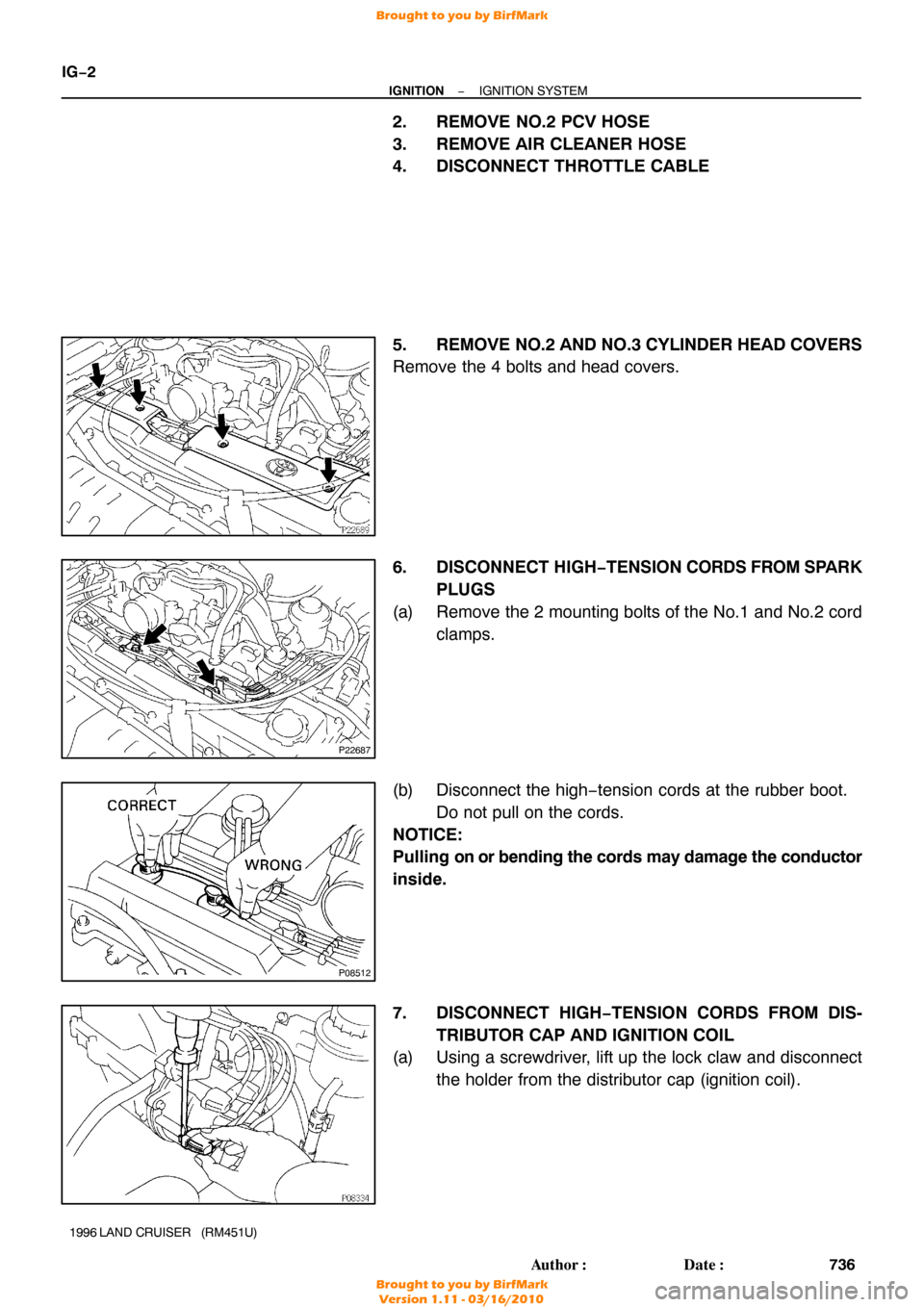
2. REMOVE NO.2 PCV HOSE
3. REMOVE AIR CLEANER HOSE
4. DISCONNECT THROTTLE CABLE
5. REMOVE NO.2 AND NO.3 CYLINDER HEAD COVERS
Remove the 4 bolts and head covers.
6. DISCONNECT HIGH −TENSION CORDS FROM SPARK
PLUGS
(a) Remove the 2 mounting bolts of the No.1 and No.2 cord clamps.
(b) Disconnect the high −tension cords at the rubber boot.
Do not pull on the cords.
NOTICE:
Pulling on or bending the cords may damage the conductor
inside.
7. DISCONNECT HIGH−TENSION CORDS FROM DIS- TRIBUTOR CAP AND IGNITION COIL
(a) Using a screwdriver, lift up the lock claw and disconnect
the holder from the distributor cap (ignition coil).
Brought to you by BirfMark
Brought to you by BirfMark
Version 1.11 - 03/16/2010

39. INSTALL AIR CLEANER HOSE AND CAP
40. INSTALL BATTERY TRAY AND BATTERY
(a) Install the battery tray with the 5 bolts.
(b) C")

DISASSEMBLY
1. REMOVE DRIVE PLATE
Uniformly loosen and remove the drive plate bolts, in several
passes, in the sequ")