Page 825 of 1399

EM1Q7−01
EM−40
−
ENGINE MECHANICAL CYLINDER HEAD
1996 LAND CRUISER (RM451U)
INSPECTION
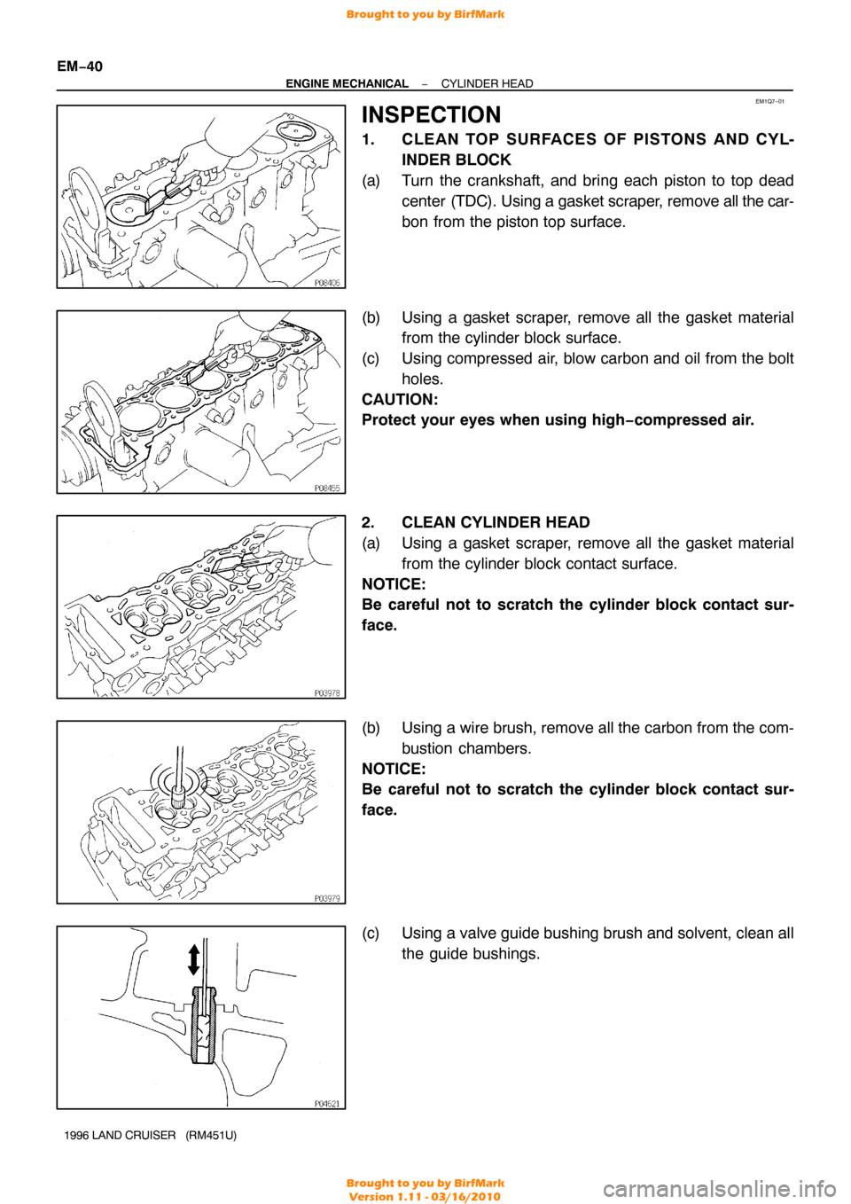
1. CLE AN TO P SURFACE S OF PIS TO NS AND CY L- INDER BLOCK
(a) Turn the crankshaft, and bring each piston to top dead center (TDC). Using a gasket scraper, remove all the car-
bon from the piston top surface.
(b) Using a gasket scraper, remove all the gasket material from the cylinder block surface.
(c) Using compressed air, blow carbon and oil from the bolt holes.
CAUTION:
Protect your eyes when using high −compressed air.
2. CLEAN CYLINDER HEAD
(a) Using a gasket scraper, remove all the gasket material from the cylinder block contact surface.
NOTICE:
Be careful not to scratch the cylinder block contact sur-
face.
(b) Using a wire brush, remove all the carbon from the com- bustion chambers.
NOTICE:
Be careful not to scratch the cylinder block contact sur-
face.
(c) Using a valve guide bushing brush and solvent, clean all the guide bushings.
Brought to you by BirfMark
Brought to you by BirfMark
Version 1.11 - 03/16/2010
Page 838 of 1399

−
ENGINE MECHANICAL CYLINDER HEAD
EM−53
1996 LAND CRUISER (RM451U)
(d) Using a plastic−faced hammer, lightly tap the valve stem
tip to ensure a proper fit.
7. INSTALL VALVE LIFTERS AND SHIMS
(a) Install the valve lifter and shim.
(b) Check that the valve lifter rotates smoothly by hand.
8. INSTALL ACCELERATOR CABLE BRACKET AND THROTTLE CABLE BRACKET
9. INSTALL 2 ENGINE WIRE CLAMP BRACKETS
10. INSTALL NO. 1 AND NO. 2 ENGINE HANGERS Torque: 41 N·m (420 kgf·cm, 30 ft·lbf)
11. INSTALL NO. 1 WATER BYPASS HOSE
12. ASSEMBLE AIR INTAKE CHAMBER AND INTAKE MANIFOLD ASSEMBLY
(a) Install 2 new gaskets and the air intake chamber with the
6 bolts and 2 nuts.
Torque: 21 N·m (210 kgf·cm, 15 ft·lbf)
(b) Connect the vacuum sensing hose to the fuel pressure regulator.
13. INSTALL AIR INTAKE CHAMBER AND INTAKE MAN- IFOLD ASSEMBLY
(a) Place a new gasket so that the rear mark is toward the rear side.
(b) Install the intake manifold with the 10 bolts and 2 nuts.
Torque: 21 N·m (210 kgf·cm, 15 ft·lbf)
(c) Connect the 2 vacuum hoses to the TVV.
14. INSTALL HEATER INLET PIPE AND HOSE
Install the heater hose to the cylinder head, and connect the
pipe to the intake manifold with the 2 bolts. Torque: 21 N·m (210 kgf·cm, 15 ft·lbf)
15. INSTALL EGR PIPE
(a) Temporarily install the union nut to the EGR valve.
(b) Install a new gasket and the EGR pipe to the cylinder head with the 2 bolts.
Torque: 21 N·m (210 kgf·cm, 15 ft·lbf)
(c) Tighten the union nut. Torque: 78 N·m (800 kgf·cm, 58 ft·lbf)
16. INSTALL WATER OUTLET
Install a new gasket and the water outlet with the 2 nuts. Torque: 21 N·m (210 kgf·cm, 15 ft·lbf)
17. INSTALL GENERATOR BRACKET
Install the generator bracket with the 2 bolts. Torque: 43 N·m (440 kgf·cm, 32 ft·lbf)
Brought to you by BirfMark
Brought to you by BirfMark
Version 1.11 - 03/16/2010
Page 839 of 1399

EM1E7−01
EM−54
−
ENGINE MECHANICAL CYLINDER HEAD
1996 LAND CRUISER (RM451U)
INSTALLATION
1. INSTALL CYLINDER HEAD AND INTAKE MANIFOLD ASSEMBLY
(a) Place the cylinder head on the cylinder head. (1) Apply seal packing to the 2 locations as shown.
Seal packing: Part No. 08826−00080 or equivalent
NOTICE:
Do not apply too much seal packing
(2) Place a new cylinder head gasket in position on the
cylinder block.
NOTICE:
Be careful of the installation direction. (3) Place the cylinder head in position on the cylinderhead gasket.
(b) Install the cylinder head bolts.
HINT:
�The cylinder head bolts are tightened in 3 progressive
steps (steps (b), (d) and (e)).
�If any cylinder head bolt is broken or deformed, replace
it.
(1) Apply a light coat of engine oil on the threads and under the heads of the cylinder head bolts.
(2) Install and uniformly tighten the 14 cylinder head
bolts and plate washers in several passes, in the se-
quence shown.
Torque: 39 N·m (400 kgf·cm, 29 ft·lbf)
If any of the cylinder head bolts does not meet the torque speci-
fication, replace the cylinder head bolt.
(3) Mark the front of the cylinder head bolt head withpaint.
(4) Retighten the cylinder head bolts by 90 ° in the nu-
merical order shown.
(5) Retighten the cylinder head bolts by an additional 90°.
(6) Check that the painted mark is now facing rearward.
Brought to you by BirfMark
Brought to you by BirfMark
Version 1.11 - 03/16/2010
Page 840 of 1399

−
ENGINE MECHANICAL CYLINDER HEAD
EM−55
1996 LAND CRUISER (RM451U)
(7) Install and torque the 2 mounting bolts.
Torque: 21N·m (210 kgf·cm, 15 ft·lbf)
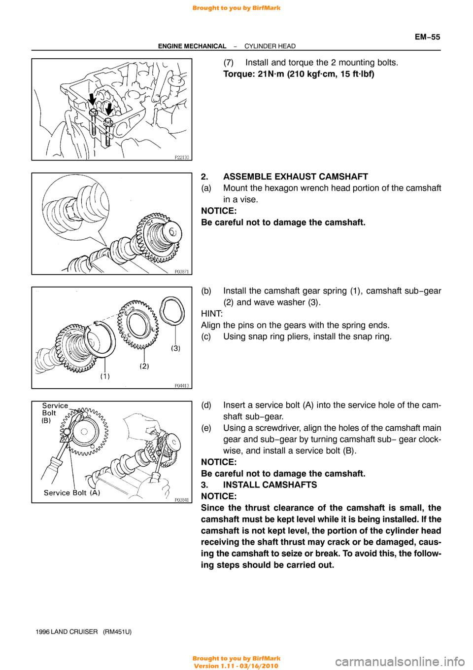
2. ASSEMBLE EXHAUST CAMSHAFT
(a) Mount the hexagon wrench head portion of the camshaft in a vise.
NOTICE:
Be careful not to damage the camshaft.
(b) Install the camshaft gear spring (1), camshaft sub −gear
(2) and wave washer (3).
HINT:
Align the pins on the gears with the spring ends.
(c) Using snap ring pliers, install the snap ring.
(d) Insert a service bolt (A) into the service hole of the cam- shaft sub−gear.
(e) Using a screwdriver, align the holes of the camshaft main
gear and sub− gear by turning camshaft sub − gear clock-
wise, and install a service bolt (B).
NOTICE:
Be careful not to damage the camshaft.
3. INSTALL CAMSHAFTS
NOTICE:
Since the thrust clearance of the camshaft is small, the
camshaft must be kept level while it is being installed. If the
camshaft is not kept level, the portion of the cylinder head
receiving the shaft thrust may crack or be damaged, caus-
ing the camshaft to seize or break. To avoid this, the follow-
ing steps should be carried out.
Brought to you by BirfMark
Brought to you by BirfMark
Version 1.11 - 03/16/2010
Page 841 of 1399

P22567A16077
2 Dot Marks
EM−56
−
ENGINE MECHANICAL CYLINDER HEAD
1996 LAND CRUISER (RM451U)
(a) Install the intake camshaft.
(1) Apply engine oil to the thrust portion of the intakecamshaft.
(2) Lightly place the intake camshaft on top of the cylin-
der head as shown in the illustration so that the No.
1 and No. 4 cylinder cam lobes face downward.
(3) Lightly push the camshaft towards the front without
applying excessive force.
(4) Place the No. 2 and No. 5 bearing caps in their prop-
er location.
(5) Temporarily tighten these bearing cap bolts uni- formly and alternately in several passes until the
bearing caps are snug with the cylinder head.
(6) Place the No. 3, No. 4, No. 6 and No. 7 bearing caps
in their proper location.
(7) Temporarily tighten these bearing cap bolts, alter- nately tightening the left and right bolts uniformly.
(8) Place the No. 1 bearing cap in its proper location. When doing this, check that there is no gap be-
tween the cylinder head and the contact surface of
bearing cap.
(9) Temporarily tighten the bearing cap bolts, alternate-
ly tightening the left and right bolts uniformly.
(10) Uniformly tighten the 14 bearing cap bolts in several
passes.
Torque: 16 N·m (160 kgf·cm, 12 ft·lbf)
(b) Install the exhaust camshaft. (1) Set the timing mark (2 dot marks) of the camshaftdrive gear at approx. 35 ° angle by turning the hexa-
gon wrench head portion of the intake camshaft
with a wrench.
Brought to you by BirfMark
Brought to you by BirfMark
Version 1.11 - 03/16/2010
Page 842 of 1399

−
ENGINE MECHANICAL CYLINDER HEAD
EM−57
1996 LAND CRUISER (RM451U)
(2) Apply engine oil to thrust portion of the exhaust
camshaft.
(3) Engage the exhaust camshaft gear to the intake
camshaft gear by matching the timing marks (two
dot marks) on each gear.
(4) Roll down the exhaust camshaft onto the bearing journals while engaging gears with each other.
(5) Lightly push the intake camshaft towards the front without applying excessive force.
(6) Install the No. 4 and No. 6 bearing caps in their proper location.
(7) Temporarily tighten the bearing cap bolts uniformly and alternately in several passes until the bearing
caps are snug with the cylinder head.
(8) Place the No. 2, No. 3, No. 5 and No. 7 bearing caps
in their proper location.
(9) Temporarily tighten these bearing cap bolts, alter- nately tightening the left and right bolts uniformly.
(10) Place the No. 1 bearing cap in its proper location. When doing this, check that there is no gap be-
tween the cylinder head and the contact surface of
bearing cap.
(11) Temporarily tighten the bearing cap bolts, alternate-
ly tightening the left and right bolts uniformly.
(12) Uniformly tighten the 14 bearing cap bolts in several
passes.
Torque: 16 N·m (160 kgf·cm, 12 ft·lbf)
(13) Bring the service bolt installed in the driven sub −
gear upward by turning the hexagon wrench head
portion of the camshaft with a wrench.
(14) Remove the service bolt.
(15) Check that the intake and exhaust camshafts turn smoothly.
Brought to you by BirfMark
Brought to you by BirfMark
Version 1.11 - 03/16/2010
Page 843 of 1399
P08374A16075
1 Dot Mark
EM−58
−
ENGINE MECHANICAL CYLINDER HEAD
1996 LAND CRUISER (RM451U)
4. SET NO.1 CYLINDER TO TDC/COMPRESSION
(a) Turn the crankshaft pulley, and align its groove with the
timing mark ”0” of the timing chain cover.
(b) Turn the camshafts so that the timing marks with 1 and 2 dots will be in straight line on the cylinder head surface as
shown in the illustration.
5. INSTALL CAMSHAFT TIMING GEAR
HINT:
Check that the matchmarks on the camshaft timing gear and
timing chain are aligned.
(a) Place the gear over the straight pin of the intake cam- shaft.
(b) Align the straight pin of distributor gear with the straight pin groove of the intake camshaft gear as shown.
(c) Hold the intake camshaft with a wrench, install and torque
the bolt.
Torque: 74 N·m (750 kgf·cm, 54 ft·lbf)
Brought to you by BirfMark
Brought to you by BirfMark
Version 1.11 - 03/16/2010
Page 845 of 1399

P03789
P08374A16075
1 Dot Mark
EM−60
−
ENGINE MECHANICAL CYLINDER HEAD
1996 LAND CRUISER (RM451U)
10. INSTALL SEMI −CIRCULAR PLUG
(a) Remove any old packing (FIPG) material.
(b) Apply seal packing to the cylinder head installation sur- face of the semi−circular plug.
Seal packing: Part No. 08826−00080 or equivalent
(c) Install the semi −circular plug to the cylinder head.
11. SET NO. 1 CYLINDER TO TDC/COMPRESSION
(a) Turn the crankshaft pulley, and align its groove with the timing mark ”0” of the timing chain cover.
(b) Check that the timing marks with 1 and 2 dots are in straight line on the cylinder head surface as shown in the
illustration.
If not, turn the crankshaft 1 revolution (360°) and align the mark
as above.
12. INSTALL CYLINDER HEAD COVER
(a) Install the gasket to the cylinder head cover.
(b) Install the cylinder head cover with the 13 bolts.
13. INSTALL WATER BYPASS OUTLET AND PIPE
(a) Install a new O−ring to the water bypass outlet.
(b) Install 2 new O−rings to the water bypass pipe.
(c) Apply soapy water to the O−rings.
(d) Assemble the water bypass outlet and pipe.
(e) Install the water bypass outlet and pipe with the 2 bolts.
Torque: 21 N·m (210 kgf·cm, 15 ft·lbf)
Brought to you by BirfMark
Brought to you by BirfMark
Version 1.11 - 03/16/2010