Page 900 of 1399
IG0152
P03783
−
IGNITION IGNITION SYSTEM
IG−5
739
Author�: Date�:
1996 LAND CRUISER (RM451U)
(b) Install the No.1 and No.2 cord clamps with the 2 bolts.
11. INSTALL NO.2 AND NO.3 CYLINDER HEAD COVERS
Install the head covers with the 4 bolts.
12. CONNECT THROTTLE CABLE
13. INSTALL AIR CLEANER HOSE
Install the air cleaner hose with the 2 clamp bolts.
14. INSTALL NO.2 PCV HOSE
15. DISCONNECT HIGH −TENSION CORDS FROM SPARK
PLUGS
16. REMOVE SPARK PLUGS
Using a 16 mm plug wrench, remove the spark plug.
17. CLEAN SPARK PLUGS
Using a spark plug cleaner or wire brush, clean the spark plug.
18. VISUALLY INSPECT SPARK PLUGS
Check the spark plug for electrode wear, threads damage and
insulator damage.
If abnormal, replace the plugs. Recommended spark plugs:
ND: K16R −U
NGK: BKR5EYA
Brought to you by BirfMark
Brought to you by BirfMark
Version 1.11 - 03/16/2010
Page 906 of 1399

IG0IE−01
−
IGNITION DISTRIBUTOR
IG−11
1996 LAND CRUISER (RM451U)
INSTALLATION
1. CHECK NO.1 CYLINDER TO TDC/COMPRESSION
If necessary, remove the cylinder head cover, and check these
conditions:
�Turn the crankshaft pulley and align its groove with
the timing mark ”0” of the timing chain cover.
�Verify that the timing marks with 1 and 2 dots are in
straight line on the cylinder head surface as shown
in the illustration.
If not, turn the crankshaft 1 revolution (360°) and align the mark
as above.
2. INSTALL DISTRIBUTOR
(a) Install a new O−ring to the distributor.
HINT:
Always use a new O −ring when installing the distributor.
(b) Align the groove of the distributor housing with the protru-
sion on the driven gear.
(c) Apply a light coat of engine oil on the O −ring.
(d) Insert the distributor, aligning the center of the flange with
that of the bolt hole on the cylinder head.
(e) Lightly tighten the hold −down bolt.
3. INSTALL DISTRIBUTOR CAP
4. CONNECT DISTRIBUTOR CONNECTOR
5. CHECK IGNITION TIMING (See page EM−10)
Brought to you by BirfMark
Brought to you by BirfMark
Version 1.11 - 03/16/2010
Page 914 of 1399
LU0KG−02
−
LUBRICATION OIL PUMP
LU−5
1996 LAND CRUISER (RM451U)
REMOVAL
HINT:
When repairing the oil pump, the oil pan and strainer should be
removed and cleaned.
1. DRAIN ENGINE OIL
2. REMOVE ENGINE UNDER COVER
3. DRAIN ENGINE COOLANT
4. REMOVE RADIATOR (See page CO−14 )
5. DISCONNECT A/C COMPRESSOR AND BRACKET
(a) Loosen the idler pulley nut and adjusting bolt, and remove
the drive belt.
(b) Remove the 4 mounting bolts, and disconnect the com- pressor from the bracket.
HINT:
Put aside the compressor, and suspend it.
(c) Remove the 5 bolts and A/C compressor bracket.
6. REMOVE RADIATOR PIPE
(a) Disconnect the No.2 radiator hose from the water inlet.
(b) Remove the 2 nuts and radiator pipe.
7. REMOVE WATER PUMP
Remove the 4 bolts, 2 nuts, water pump and gasket.
8. REMOVE CYLINDER HEAD (See page EM−28 )
9. DISCONNECT OIL COOLER PIPE BRACKET FROM NO.1 OIL PAN
Brought to you by BirfMark
Brought to you by BirfMark
Version 1.11 - 03/16/2010
Page 922 of 1399

−
LUBRICATION OIL PUMP
LU−13
1996 LAND CRUISER (RM451U)
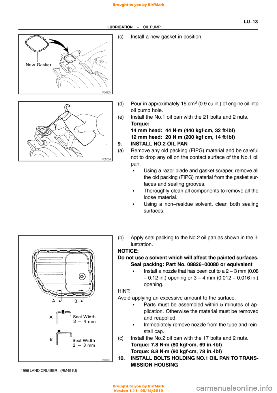
(c) Install a new gasket in position.
(d) Pour in approximately 15 cm
3 (0.9 cu in.) of engine oil into
oil pump hole.
(e) Install the No.1 oil pan with the 21 bolts and 2 nuts. Torque:
14 mm head: 44 N·m (440 kgf·cm, 32 ft·lbf)
12 mm head: 20 N·m (200 kgf·cm, 14 ft·lbf)
9. INSTALL NO.2 OIL PAN
(a) Remove any old packing (FIPG) material and be careful not to drop any oil on the contact surface of the No.1 oil
pan.
�Using a razor blade and gasket scraper, remove all
the old packing (FIPG) material from the gasket sur-
faces and sealing grooves.
�Thoroughly clean all components to remove all the
loose material.
�Using a non −residue solvent, clean both sealing
surfaces.
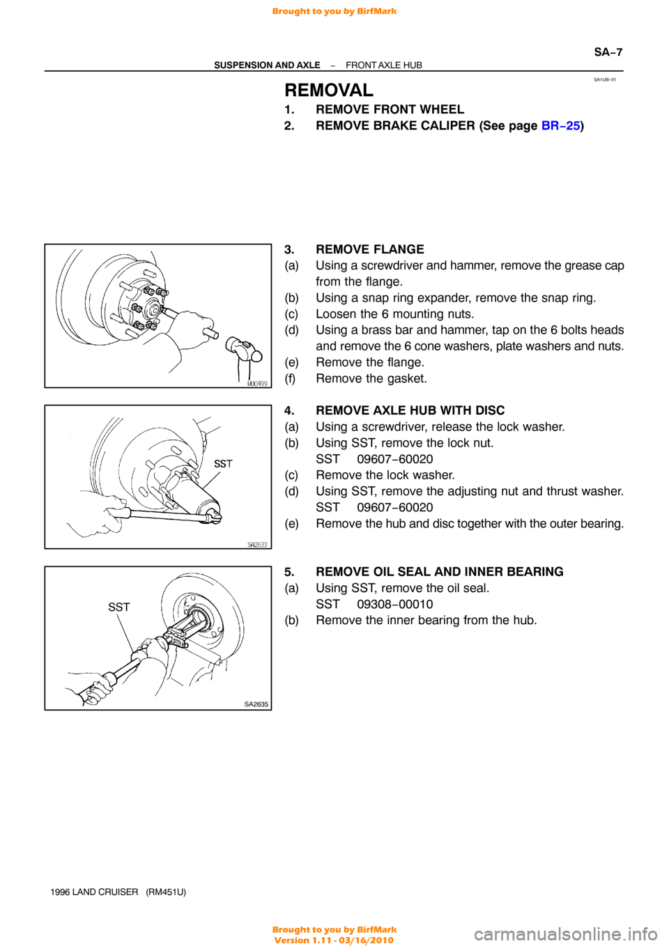
(b) Apply seal packing to the No.2 oil pan as shown in the il- lustration.
NOTICE:
Do not use a solvent which will affect the painted surfaces. Seal packing: Part No. 08826−00080 or equivalent
�Install a nozzle that has been cut to a 2 − 3 mm (0.08
− 0.12 in.) opening or 3 − 4 mm (0.012 − 0.016 in.)
opening.
HINT:
Avoid applying an excessive amount to the surface.
�Parts must be assembled within 5 minutes of ap-
plication. Otherwise the material must be removed
and reapplied.
�Immediately remove nozzle from the tube and rein-
stall cap.
(c) Install the No.2 oil pan with the 17 bolts and 2 nuts. Torque: 7.8 N·m (80 kgf·cm, 69 in.·lbf)
Torque: 8.8 N·m (90 kgf·cm, 78 in.·lbf)
10. INSTALL BOL TS HOLDING NO.1 OIL PAN TO TRANS-
MISSION HOUSING
Brought to you by BirfMark
Brought to you by BirfMark
Version 1.11 - 03/16/2010
Page 923 of 1399

LU−14
−
LUBRICATION OIL PUMP
1996 LAND CRUISER (RM451U)
Install the 6 bolts.
Torque: 72 N·m (730 kgf·cm, 53 ft·lbf)
11. INSTALL OIL LEVEL SENSOR
(a) Install a new gasket to the level sensor.
(b) Install the level sensor with the 4 bolts. Torque: 5.4 N·m (55 kgf·cm, 48 in.·lbf)
12. CONNECT OIL COOLER PIPE BRACKET TO NO.1 OIL
PA N
13. INSTALL CYLINDER HEAD(See page EM−54)
14. INSTALL WATER PUMP
Install a new gasket and water pump with the 4 bolts and 2 nuts. Torque: 21 N·m (210 kgf·cm, 15 ft·lbf)
15. INSTALL RADIATOR PIPE
(a) Connect the No.2 radiator hose to the water inlet.
(b) Install the 2 nuts holding the radiator pipe to the No.1 oil pan.
Torque: 21 N·m (210 kgf·cm, 15 ft·lbf)
16. INSTALL A/C COMPRESSOR AND BRACKET
(a) Install the A/C compressor bracket with the 5 bolts. Torque: 37 N·m (375 kgf·cm, 27 ft·lbf)
(b) Install the A/C compressor with the 4 bolts.
Torque: 25 N·m (250 kgf·cm, 18 ft·lbf)
(c) Install and adjust the drive belt (See page CH−2).
17. INSTALL RADIATOR (See page CO−16 )
18. INSTALL ENGINE UNDER COVER
19. FILL WITH ENGINE OIL
20. START ENGINE AND CHECK FOR LEAKS
Brought to you by BirfMark
Brought to you by BirfMark
Version 1.11 - 03/16/2010
Page 1070 of 1399

SA1UB−01
SA2635
SST
−
SUSPENSION AND AXLE FRONT AXLE HUB
SA−7
1996 LAND CRUISER (RM451U)
REMOVAL
1. REMOVE FRONT WHEEL
2. REMOVE BRAKE CALIPER (See page BR−25 )
3. REMOVE FLANGE
(a) Using a screwdriver and hammer, remove the grease cap
from the flange.
(b) Using a snap ring expander, remove the snap ring.
(c) Loosen the 6 mounting nuts.
(d) Using a brass bar and hammer, tap on the 6 bolts heads and remove the 6 cone washers, plate washers and nuts.
(e) Remove the flange.
(f) Remove the gasket.
4. REMOVE AXLE HUB WITH DISC
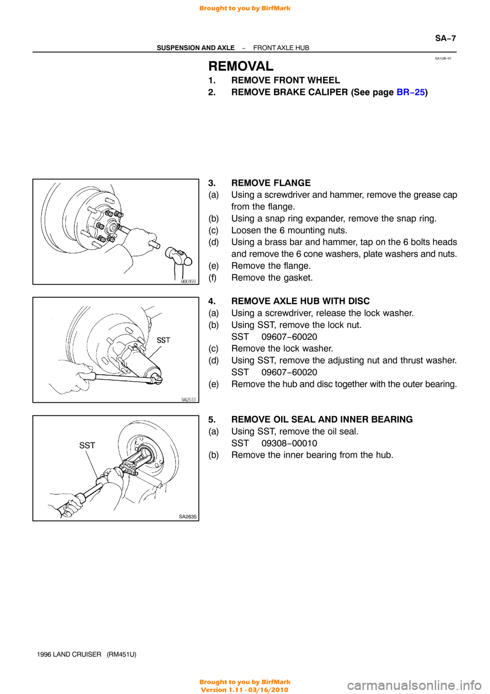
(a) Using a screwdriver, release the lock washer.
(b) Using SST, remove the lock nut. SST 09607−60020
(c) Remove the lock washer.
(d) Using SST, remove the adjusting nut and thrust washer.
SST 09607−60020
(e) Remove the hub and disc together with the outer bearing.
5. REMOVE OIL SEAL AND INNER BEARING
(a) Using SST, remove the oil seal. SST 09308−00010
(b) Remove the inner bearing from the hub.
Brought to you by BirfMark
Brought to you by BirfMark
Version 1.11 - 03/16/2010
Page 1071 of 1399

SA1UB−01
SA2635
SST
−
SUSPENSION AND AXLE FRONT AXLE HUB
SA−7
1996 LAND CRUISER (RM451U)
REMOVAL
1. REMOVE FRONT WHEEL
2. REMOVE BRAKE CALIPER (See page BR−25 )
3. REMOVE FLANGE
(a) Using a screwdriver and hammer, remove the grease cap
from the flange.
(b) Using a snap ring expander, remove the snap ring.
(c) Loosen the 6 mounting nuts.
(d) Using a brass bar and hammer, tap on the 6 bolts heads and remove the 6 cone washers, plate washers and nuts.
(e) Remove the flange.
(f) Remove the gasket.
4. REMOVE AXLE HUB WITH DISC
(a) Using a screwdriver, release the lock washer.
(b) Using SST, remove the lock nut. SST 09607−60020
(c) Remove the lock washer.
(d) Using SST, remove the adjusting nut and thrust washer.
SST 09607−60020
(e) Remove the hub and disc together with the outer bearing.
5. REMOVE OIL SEAL AND INNER BEARING
(a) Using SST, remove the oil seal. SST 09308−00010
(b) Remove the inner bearing from the hub.
Brought to you by BirfMark
Brought to you by BirfMark
Version 1.11 - 03/16/2010
Page 1076 of 1399

SA1UG−01
W00495
SA2644
SST
R08383
R13137
−
SUSPENSION AND AXLE STEERING KNUCKLE AND AXLE SHAFT
SA−13
1996 LAND CRUISER (RM451U)
REMOVAL
1. REMOVE FRONT AXLE HUB (See page SA−7 )
2. REMOVE ABS SPEED SENSOR
Remove the 2 bolts and disconnect the speed sensor from the
steering knuckle.
3. REMOVE DUST SEAL AND DUST COVER
Remove the 8 bolts, dust seal, dust cover and gasket.
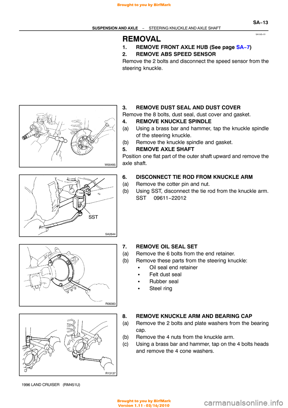
4. REMOVE KNUCKLE SPINDLE
(a) Using a brass bar and hammer, tap the knuckle spindle of the steering knuckle.
(b) Remove the knuckle spindle and gasket.
5. REMOVE AXLE SHAFT
Position one flat part of the outer shaft upward and remove the
axle shaft.
6. DISCONNECT TIE ROD FROM KNUCKLE ARM
(a) Remove the cotter pin and nut.
(b) Using SST, disconnect the tie rod from the knuckle arm. SST 09611 −22012
7. REMOVE OIL SEAL SET
(a) Remove the 6 bolts from the end retainer.
(b) Remove these parts from the steering knuckle:
�Oil seal end retainer
�Felt dust seal
�Rubber seal
�Steel ring
8. REMOVE KNUCKLE ARM AND BEARING CAP
(a) Remove the 2 bolts and plate washers from the bearing cap.
(b) Remove the 4 nuts from the knuckle arm.
(c) Using a brass bar and hammer, tap on the 4 bolts heads and remove the 4 cone washers.
Brought to you by BirfMark
Brought to you by BirfMark
Version 1.11 - 03/16/2010