Page 1213 of 1399
−
SFI INJECTOR
SF−27
1996 LAND CRUISER (RM451U)
18. DISCONNECT PS RESERVOIR TANK
Remove the 3 bolts and disconnect the reservoir tank.
19. REMOVE ENGINE OIL DIPSTICK
20. DISCONNECT GROUND STRAP
21. REMOVE INTAKE MANIFOLD STAY
Remove the 2 bolts and intake manifold stay.
22. DISCONNECT VACUUM HOSES FROM TVV
23. DISCONNECT NO.1 WATER BYPASS HOSE FROM
CYLINDER HEAD
24. REMOVE AIR INTAKE CHAMBER
Remove the 6 bolts, 2 nuts, air intake chamber and 2 gaskets.
25. REMOVE FUEL RETURN PIPE
(a) Disconnect the fuel hose from the fuel pressure regulator.
(b) Remove the 2 bolts and fuel return pipe.
Brought to you by BirfMark
Brought to you by BirfMark
Version 1.11 - 03/16/2010
Page 1219 of 1399
−
SFI INJECTOR
SF−33
1996 LAND CRUISER (RM451U)
(k) Connect the 6 injector connectors as shown.
2. INSTALL FUEL INLET PIPE
Install the fuel inlet pipe with 4 new gaskets, the 2 union bolts
and bolt.
Torque:
Union bolt: 29 N·m (300 kgf·cm, 22 ft·lbf)
Bolt: 20 N·m (200 kgf·cm, 14 ft·lbf)
3. INSTALL FUEL RETURN PIPE
(a) Install the fuel return pipe with the 2 bolts. Torque: 20 N·m (200 kgf·cm, 14 ft·lbf)
(b) Connect the fuel hose to the fuel pressure regulator.
4. INSTALL AIR INTAKE CHAMBER
Install 2 new gaskets and the air intake chamber with the 6 bolts
and 2 nuts. Torque: 21 N·m (210 kgf·cm, 15 ft·lbf)
5. CONNECT NO.1 WATER BYPASS HOSE TO CYL- INDER HEAD
6. CONNECT VACUUM HOSES TO TVV
Brought to you by BirfMark
Brought to you by BirfMark
Version 1.11 - 03/16/2010
Page 1264 of 1399

SR16B−02
−
STEERING TILT STEERING COLUMN
SR−13
1996 LAND CRUISER (RM451U)
DISASSEMBLY
NOTICE:
When using a vise, do not overtighten it.
1. DISCONNECT UNIVERSAL JOINT
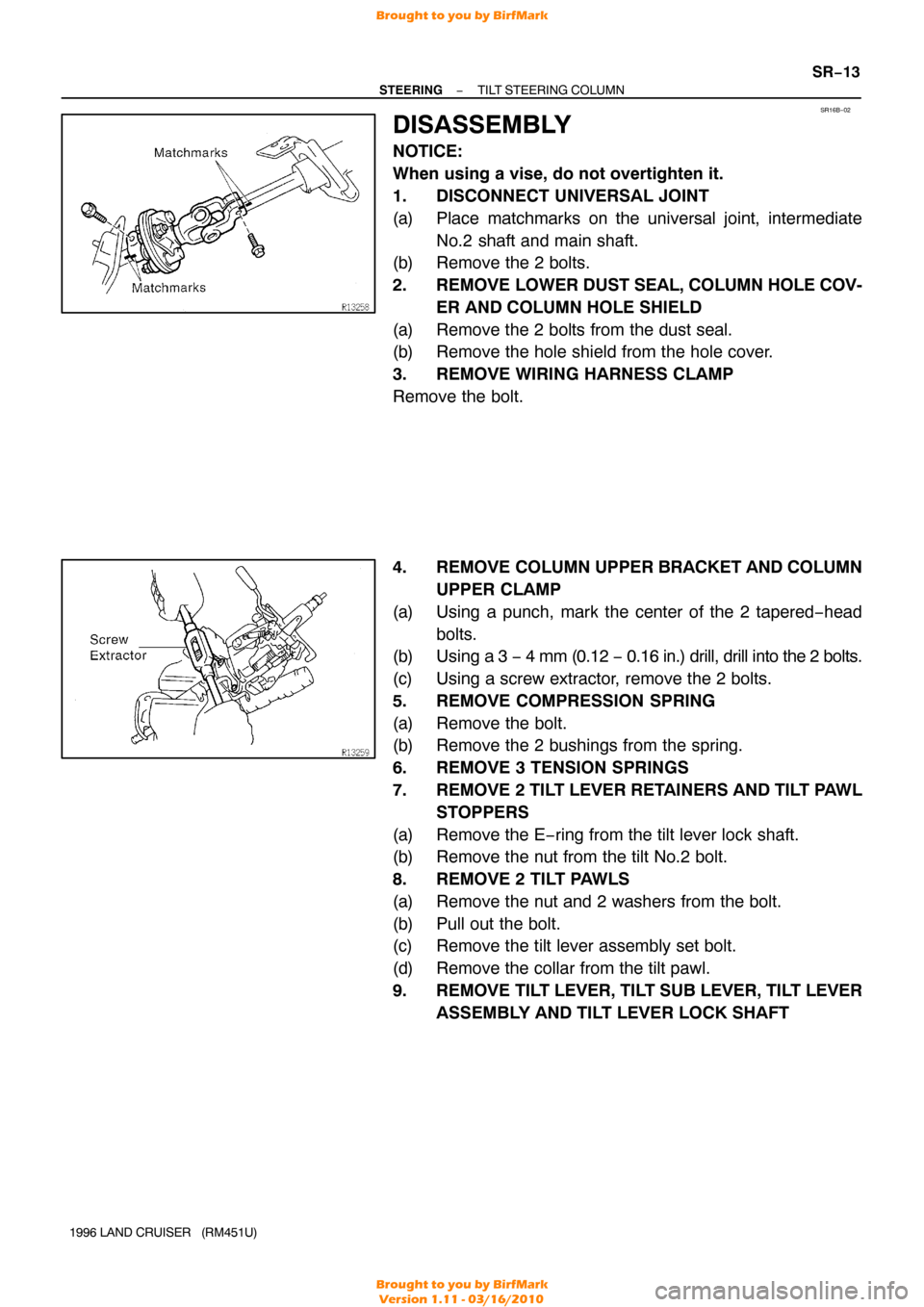
(a) Place matchmarks on the universal joint, intermediate
No.2 shaft and main shaft.
(b) Remove the 2 bolts.
2. REMOVE LOWER DUST SEAL, COLUMN HOLE COV-
ER AND COLUMN HOLE SHIELD
(a) Remove the 2 bolts from the dust seal.
(b) Remove the hole shield from the hole cover.
3. REMOVE WIRING HARNESS CLAMP
Remove the bolt.
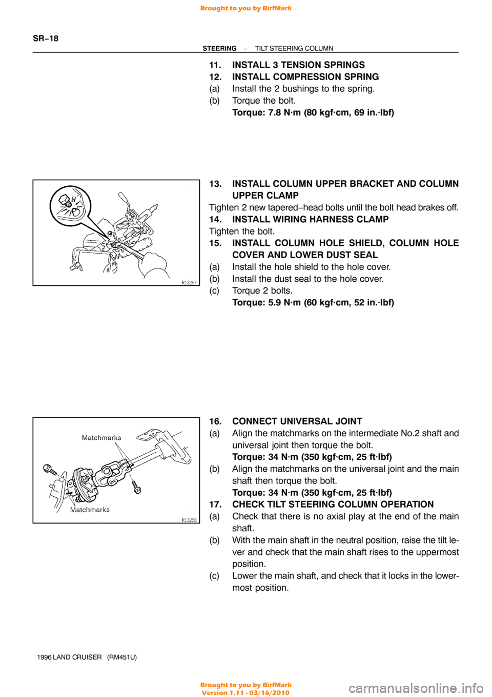
4. REMOVE COLUMN UPPER BRACKET AND COLUMN UPPER CLAMP
(a) Using a punch, mark the center of the 2 tapered−head bolts.
(b) Using a 3 − 4 mm (0.12 − 0.16 in.) drill, drill into the 2 bolts.
(c) Using a screw extractor, remove the 2 bolts.
5. REMOVE COMPRESSION SPRING
(a) Remove the bolt.
(b) Remove the 2 bushings from the spring.
6. REMOVE 3 TENSION SPRINGS
7. REMOVE 2 TILT LEVER RETAINERS AND TILT PAWL STOPPERS
(a) Remove the E−ring from the tilt lever lock shaft.
(b) Remove the nut from the tilt No.2 bolt.
8. REMOVE 2 TILT PAWLS
(a) Remove the nut and 2 washers from the bolt.
(b) Pull out the bolt.
(c) Remove the tilt lever assembly set bolt.
(d) Remove the collar from the tilt pawl.
9. REMOVE TILT LEVER, TILT SUB LEVER, TILT LEVER ASSEMBLY AND TILT LEVER LOCK SHAFT
Brought to you by BirfMark
Brought to you by BirfMark
Version 1.11 - 03/16/2010
Page 1269 of 1399

SR−18
−
STEERING TILT STEERING COLUMN
1996 LAND CRUISER (RM451U)
11. INSTALL 3 TENSION SPRINGS
12. INSTALL COMPRESSION SPRING
(a) Install the 2 bushings to the spring.
(b) Torque the bolt.
Torque: 7.8 N·m (80 kgf·cm, 69 in.·lbf)
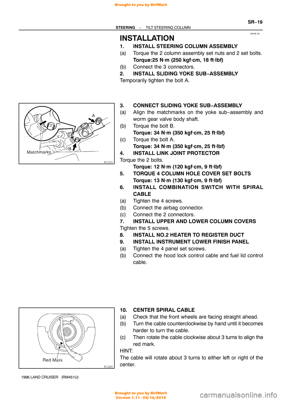
13. INSTALL COLUMN UPPER BRACKET AND COLUMN UPPER CLAMP
Tighten 2 new tapered −head bolts until the bolt head brakes off.
14. INSTALL WIRING HARNESS CLAMP
Tighten the bolt.
15. INSTALL COLUMN HOLE SHIELD, COLUMN HOLE COVER AND LOWER DUST SEAL
(a) Install the hole shield to the hole cover.
(b) Install the dust seal to the hole cover.
(c) Torque 2 bolts. Torque: 5.9 N·m (60 kgf·cm, 52 in.·lbf)
16. CONNECT UNIVERSAL JOINT
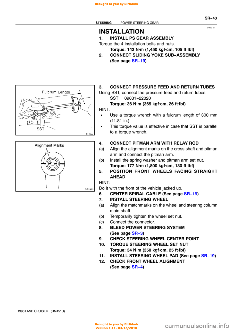
(a) Align the matchmarks on the intermediate No.2 shaft and
universal joint then torque the bolt.
Torque: 34 N·m (350 kgf·cm, 25 ft·lbf)
(b) Align the matchmarks on the universal joint and the main shaft then torque the bolt.
Torque: 34 N·m (350 kgf·cm, 25 ft·lbf)
17. CHECK TILT STEERING COLUMN OPERATION
(a) Check that there is no axial play at the end of the main
shaft.
(b) With the main shaft in the neutral position, raise the tilt le- ver and check that the main shaft rises to the uppermost
position.
(c) Lower the main shaft, and check that it locks in the lower-
most position.
Brought to you by BirfMark
Brought to you by BirfMark
Version 1.11 - 03/16/2010
Page 1270 of 1399

SR16E−03
−
STEERING TILT STEERING COLUMN
SR−19
1996 LAND CRUISER (RM451U)
INSTALLATION
1. INSTALL STEERING COLUMN ASSEMBLY
(a) Torque the 2 column assembly set nuts and 2 set bolts.
Torque:25 N·m (250 kgf·cm, 18 ft·lbf)
(b) Connect the 3 connectors.
2. INSTALL SLIDING YOKE SUB −ASSEMBLY
Temporarily tighten the bolt A.
3. CONNECT SLIDING YOKE SUB−ASSEMBLY
(a) Align the matchmarks on the yoke sub−assembly and
worm gear valve body shaft.
(b) Torque the bolt B. Torque: 34 N·m (350 kgf·cm, 25 ft·lbf)
(c) Torque the bolt A.
Torque: 34 N·m (350 kgf·cm, 25 ft·lbf)
4. INSTALL LINK JOINT PROTECTOR
Torque the 2 bolts. Torque: 12 N·m (120 kgf·cm, 9 ft·lbf)
5. TORQUE 4 COLUMN HOLE COVER SET BOLTS Torque: 13 N·m (130 kgf·cm, 9 ft·lbf)
6. INSTALL COMBINATION SWITCH WITH SPIRAL CABLE
(a) Tighten the 4 screws.
(b) Connect the airbag connector.
(c) Connect the 2 connectors.
7. INSTALL UPPER AND LOWER COLUMN COVERS
Tighten the 5 screws.
8. INSTALL NO.2 HEATER TO REGISTER DUCT
9. INSTALL INSTRUMENT LOWER FINISH PANEL
(a) Tighten the 4 panel set screws.
(b) Connect the hood lock control cable and fuel lid control cable.
10. CENTER SPIRAL CABLE
(a) Check that the front wheels are facing straight ahead.
(b) Turn the cable counterclockwise by hand until it becomes harder to turn the cable.
(c) Then rotate the cable clockwise about 3 turns to align the
red mark.
HINT:
The cable will rotate about 3 turns to either left or right of the
center.
Brought to you by BirfMark
Brought to you by BirfMark
Version 1.11 - 03/16/2010
Page 1288 of 1399
SR16M−01
−
STEERING POWER STEERING GEAR
SR−35
1996 LAND CRUISER (RM451U)
REMOVAL
1. PLACE FRONT WHEELS FACING STRAIGHT AHEAD
2. REMOVE STEERING WHEEL PAD (See page SR−11)
3. REMOVE STEERING WHEEL (See page SR−11)
4. REMOVE FRAME SEAL
5. REMOVE LINK JOINT PROTECTOR
Remove the 2 bolts.
6. DISCONNECT PITMAN ARM WITH RELAY ROD
(a) Remove the pitman arm set nut and spring washer.
(b) Using SST, disconnect the pitman arm from the gear as- sembly.
SST 09628−62011
7. DISCONNECT PRESSURE FEED AND RETURN TUBES
Using SST, disconnect the pressure feed and return tubes. SST 09631−22020
8. DISCONNECT SLIDING YOKE SUB−ASSEMBLY
(See page SR−13 )
9. REMOVE PS GEAR ASSEMBLY
Remove the 4 installation bolts and nuts.
Brought to you by BirfMark
Brought to you by BirfMark
Version 1.11 - 03/16/2010
Page 1296 of 1399

SR16Q−01
SR2922
Alignment Marks
−
STEERING POWER STEERING GEAR
SR−43
1996 LAND CRUISER (RM451U)
INSTALLATION
1. INSTALL PS GEAR ASSEMBLY
Torque the 4 installation bolts and nuts.
Torque: 142 N·m (1,450 kgf·cm, 105 ft·lbf)
2. CONNECT SLIDING YOKE SUB−ASSEMBLY (See page SR−19 )
3. CONNECT PRESSURE FEED AND RETURN TUBES
Using SST, connect the pressure feed and return tubes. SST 09631−22020
Torque: 36 N·m (365 kgf·cm, 26 ft·lbf)
HINT:
�Use a torque wrench with a fulcrum length of 300 mm
(11.81 in.).
�This torque value is effective in case that SST is parallel
to a torque wrench.
4. CONNECT PITMAN ARM WITH RELAY ROD
(a) Align the alignment marks on the cross shaft and pitman arm and connect the pitman arm.
(b) Install the spring washer and pitman arm set nut. Torque: 177 N·m (1,800 kgf·cm, 130 ft·lbf)
5. POSITION FRONT WHEELS FACING STRAIGHT AHEAD
HINT:
Do it with the front of the vehicle jacked up.
6. CENTER SPIRAL CABLE (See page SR−19 )
7. INSTALL STEERING WHEEL
(a) Align the matchmarks on the wheel and steering column main shaft.
(b) Temporarily tighten the wheel set nut.
(c) Connect the connector.
8. BLEED POWER STEERING SYSTEM
(See page SR−3 )
9. CHECK STEERING WHEEL CENTER POINT
10. TORQUE STEERING WHEEL SET NUT
Torque: 34 N·m (350 kgf·cm, 25 ft·lbf)
11. INSTALL STEERING WHEEL PAD (See page SR−19)
12. CHECK FRONT WHEEL ALIGNMENT (See page SR−4 )
Brought to you by BirfMark
Brought to you by BirfMark
Version 1.11 - 03/16/2010
Page 1302 of 1399
SS00F−01
V06821
MarkMark
Class
Class
Hexagon head
bolt Bolt
head No.4−
5−
6−
7−
8−
9−
10−
11 − 4T
5T 6T
7T 8T
9T
10T 11 T
No mark
No mark
Hexagon
flange bolt
w/ washer
hexagon bolt 4T
4T
5T
6T
7T
8T
Hexagon
head
bolt
Hexagon
flange bolt w/ washer
hexagon bolt
Hexagon head
bolt
Hexagon head
bolt 2
Protruding
lines
2
Protruding
lines
3
Protruding
lines
4
Protruding
lines Hexagon
flange bolt
w/ washer
hexagon bolt
Hexagon
flange boltw/ washer
hexagon bolt
Hexagon
flange bolt
w/ washer
hexagon bolt
Stud bolt
Welded bolt 4
Protruding
lines
5
Protruding
lines
6
Protruding
lines
No mark
Grooved
9T
10T 11 T
4T
6T
4T
−
SERVICE SPECIFICATIONS STANDARD BOLT
SS−1
124
Author�: Date�:
1996 LAND CRUISER (RM451U)
STANDARD BOLT
HOW TO DETERMINE BOLT STRENGTH
Brought to you by BirfMark
Brought to you by BirfMark
Version 1.11 - 03/16/2010