Page 871 of 1399

EXAMPLE: Connecting rod ”3” + Crankshaft ”1”= Total number 4 (Use bearing ”4”)
Number marked
Connecting rod
Crankshaft
Use bearing 123
2
2 22
3
3 3
3 3
4445 56
111
EM−86
−
ENGINE MECHANICAL CYLINDER BLOCK
1996 LAND CRUISER (RM451U)
(h) Install the connecting rod cap with the 2 nuts (See page EM−103 ).
NOTICE:
Do not turn the crankshaft.
(i) Remove the 2 nuts and connecting rod cap (See proce-
dure (b) and (c) above).
(j) Measure the Plastigage at its widest point. Standard oil clearance:
STD0.032 − 0.050 mm (0.0013 − 0.0020 in.)
U/S 0.250.033 − 0.073 mm (0.0013 − 0.0029 in.)
Maximum oil clearance: 0.10 mm (0.0039 in.)
If the oil clearance is greater than maximum, replace the bear-
ings. If necessary, grind or replace the crankshaft.
HINT:
If using a standard bearing, replace with one having the same
number. If the number of the bearing cannot be determined, se-
lect the correct bearing by adding together the numbers im-
printed on the connecting rod and crankshaft, then selecting
the bearing with the same number as the total. There are 5 sizes
of standard bearings, marked ”2”, ”3”, ”4”, ”5” and ”6” according-
ly.
Reference
Connecting rod big end inside diameter:
Mark ”1”60.526 − 60.532 mm (2.3829 − 2.3831 in.)
Mark ”2”60.532 − 60.538 mm (2.3831 − 2.3834 in.)
Mark ”3”60.538 − 60.544 mm (2.3834 − 2.3836 in.)
Crankshaft crank pin diameter:
Mark ”1”56.994 − 57.000 mm (2.2439 − 2.2441 in.)
Mark ”2”56.988 − 56.994 mm (2.2436 − 2.2439 in.)
Mark ”3”56.982 − 56.988 mm (2.2434 − 2.2436 in.)
Brought to you by BirfMark
Brought to you by BirfMark
Version 1.11 - 03/16/2010
Page 872 of 1399

P04620
−
ENGINE MECHANICAL CYLINDER BLOCK
EM−87
1996 LAND CRUISER (RM451U)
Standard sized bearing center wall thickness:
Mark ”2”1.744 − 1.747 mm (0.0687 − 0.0688 in.)
Mark ”3”1.747 − 1.750 mm (0.0688 − 0.0689 in.)
Mark ”4”1.750 − 1.753 mm (0.0689 − 0.0690 in.)
Mark ”5”1.753 − 1.756 mm (0.0690 − 0.0691 in.)
Mark ”6”1.756 − 1.759 mm (0.0691 − 0.0693 in.)
(k) Completely remove the Plastigage.
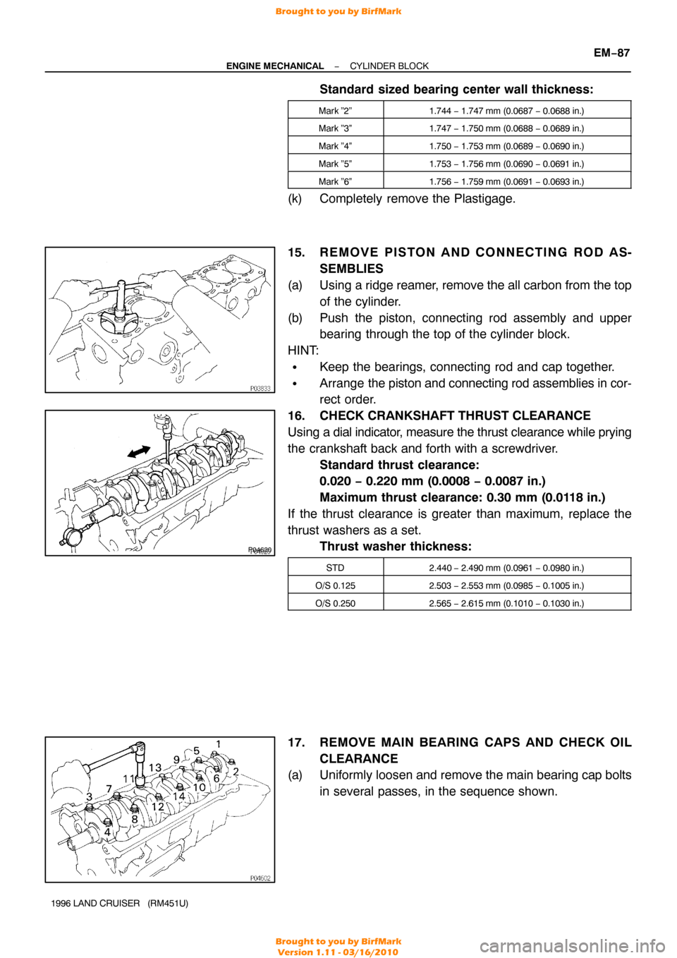
15. R E M O V E P I S TO N A N D C O N N E C T I N G R O D A S-
SEMBLIES
(a) Using a ridge reamer, remove the all carbon from the top of the cylinder.
(b) Push the piston, connecting rod assembly and upper bearing through the top of the cylinder block.
HINT:
�Keep the bearings, connecting rod and cap together.
�Arrange the piston and connecting rod assemblies in cor-
rect order.
16. CHECK CRANKSHAFT THRUST CLEARANCE
Using a dial indicator, measure the thrust clearance while prying
the crankshaft back and forth with a screwdriver. Standard thrust clearance:
0.020 − 0.220 mm (0.0008 − 0.0087 in.)
Maximum thrust clearance: 0.30 mm (0.0118 in.)
If the thrust clearance is greater than maximum, replace the
thrust washers as a set. Thrust washer thickness:
STD2.440 − 2.490 mm (0.0961 − 0.0980 in.)
O/S 0.1252.503 − 2.553 mm (0.0985 − 0.1005 in.)
O/S 0.2502.565 − 2.615 mm (0.1010 − 0.1030 in.)
17. REMOVE MAIN BEARING CAPS AND CHECK OIL
CLEARANCE
(a) Uniformly loosen and remove the main bearing cap bolts
in several passes, in the sequence shown.
Brought to you by BirfMark
Brought to you by BirfMark
Version 1.11 - 03/16/2010
Page 874 of 1399

EXAMPLE: Cylinder block ”2” + Crankshaft ”1”= Total number 3 (Use bearing ”3”)
Number marked
Cylinder block
Crankshaft
Use bearing 123
2
2 22
3
3 3
3 3
4445 56
111
−
ENGINE MECHANICAL CYLINDER BLOCK
EM−89
1996 LAND CRUISER (RM451U)
(j) Measure the Plastigage at its widest point.
Standard clearance:
STD0.042 − 0.060 mm (0.0017 − 0.0024 in.)
U/S 0.250.041 − 0.081 mm (0.0016 − 0.0032 in.)
Maximum clearance: 0.10 mm (0.0039 in.)
If the oil clearance is greater than maximum, replace the bear-
ings. If necessary, grind or replace the crankshaft.
HINT:
If using a standard bearing, replace with one having the same
number. If the number of the bearing cannot be determined, se-
lect the correct bearing by adding together the numbers im-
printed on the cylinder block and crankshaft, then selecting the
bearing with the same number as the total. There are 5 sizes
of standard bearings, marked ”2”, ”3”, ”4”, ”5” and ”6”\
accorking-
ly.
Reference
Cylinder block main journal bore diameter:
Mark ”1”74.026 − 74.032 mm (2.9144 − 2.9146 in.)
Mark ”2”74.032 − 74.038 mm (2.9146 − 2.9149 in.)
Mark ”3”74.038 − 74.044 mm (2.9149 − 2.9151 in.)
Crankshaft main journal diameter:
Mark ”1”68.994 − 69.000 mm (2.7163 − 2.7165 in.)
Mark ”2”68.988 − 68.994 mm (2.7161 − 2.7163 in.)
Mark ”3”68.982 − 68.988 mm (2.7158 − 2.7161 in.)
Standard bearing center wall thickness:
Mark ”2”2.489 − 2.492 mm (0.0980 − 0.0981 in.)
Mark ”2”2.492 − 2.495 mm (0.0981 − 0.0982 in.)
Mark ”3”2.495 − 2.498 mm (0.0982 − 0.0983 in.)
Mark ”4”2.498 − 2.501 mm (0.0983 − 0.0985 in.)
Mark ”5”2.501 − 2.504 mm (0.0985 − 0.0986 in.)
(k) Completely remove the Plastigage.
18. REMOVE CRANKSHAFT
(a) Lift out the crankshaft.
(b) Remove the upper main bearings and upper thrust wash-
ers from the cylinder block.
HINT:
Arrange the main bearings and thrust washers in correct order.
Brought to you by BirfMark
Brought to you by BirfMark
Version 1.11 - 03/16/2010
Page 875 of 1399
P04628
EM−90
−
ENGINE MECHANICAL CYLINDER BLOCK
1996 LAND CRUISER (RM451U)
19. REMOVE CHECK VALVES AND OIL NOZZLES
Remove the 6 check valves and oil nozzles.
20. REMOVE CYLINDER BLOCK ORIFICE
21. CHECK FIT BETWEEN PISTON AND PISTON PIN
Try to move the piston back and forth on the piston pin.
If any movement is felt, replace the piston and pin as a set.
22. REMOVE PISTON RINGS
(a) Using a piston ring expander, remove the 2 compression
rings.
(b) Remove the 2 side rails and oil ring by hand.
HINT:
Arrange the rings in correct order only.
Brought to you by BirfMark
Brought to you by BirfMark
Version 1.11 - 03/16/2010
Page 878 of 1399

−
ENGINE MECHANICAL CYLINDER BLOCK
EM−93
1996 LAND CRUISER (RM451U)
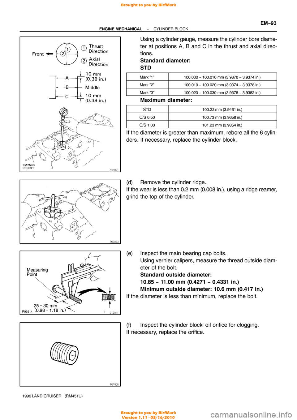
Using a cylinder gauge, measure the cylinder bore diame-
ter at positions A, B and C in the thrust and axial direc-
tions.
Standard diameter:
STD
Mark ”1”100.000 − 100.010 mm (3.9370 − 3.9374 in.)
Mark ”2”100.010 − 100.020 mm (3.9374 − 3.9378 in.)
Mark ”3”100.020 − 100.030 mm (3.9378 − 3.9382 in.)
Maximum diameter:
STD100.23 mm (3.9461 in.)
O/S 0.50100.73 mm (3.9658 in.)
O/S 1.00101.23 mm (3.9854 in.)
If the diameter is greater than maximum, rebore all the 6 cylin-
ders. If necessary, replace the cylinder block.
(d) Remove the cylinder ridge.
If the wear is less than 0.2 mm (0.008 in.), using a ridge reamer,
grind the top of the cylinder.
(e) Inspect the main bearing cap bolts.
Using vernier calipers, measure the thread outside diam-
eter of the bolt.
Standard outside diameter:
10.85 − 11.00 mm (0.4271 − 0.4331 in.)
Minimum outside diameter: 10.6 mm (0.417 in.)
If the diameter is less than minimum, replace the bolt.
(f) Inspect the cylinder blockl oil orifice for clogging.
If necessary, replace the orifice.
Brought to you by BirfMark
Brought to you by BirfMark
Version 1.11 - 03/16/2010
Page 879 of 1399
EM−94
−
ENGINE MECHANICAL CYLINDER BLOCK
1996 LAND CRUISER (RM451U)
3. INSPECT BEARING OF OIL PUMP DRIVE SHAFT
GEAR
Check the bearing for pitting and scratches.
If the bearing is damaged, replace the cylinder block.
4. CLEAN PISTON
(a) Using a gasket scraper, remove the carbon from the pis-
ton top.
(b) Using a groove cleaning tool or broken ring, clean the pis-
ton ring grooves.
(c) Using solvent and a brush, thoroughly clean the piston.
NOTICE:
Do not use a wire brush.
5. INSPECT PISTON AND CONNECTING ROD
(a) Inspect the piston oil clearance.
HINT:
There are 3 sizes of the standard piston diameter , marked ”1”,
”2” and ”3”. The mark is stamped on the piston top.
Brought to you by BirfMark
Brought to you by BirfMark
Version 1.11 - 03/16/2010
Page 880 of 1399

−
ENGINE MECHANICAL CYLINDER BLOCK
EM−95
1996 LAND CRUISER (RM451U)
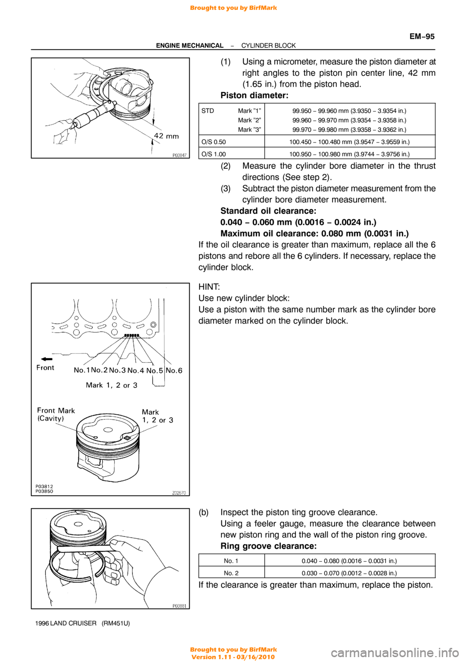
(1) Using a micrometer, measure the piston diameter at
right angles to the piston pin center line, 42 mm
(1.65 in.) from the piston head.
Piston diameter:
STD Mark ”1”
Mark ”2”
Mark ”3”99.950 − 99.960 mm (3.9350 − 3.9354 in.)
99.960 − 99.970 mm (3.9354 − 3.9358 in.)
99.970 − 99.980 mm (3.9358 − 3.9362 in.)
O/S 0.50100.450 − 100.480 mm (3.9547 − 3.9559 in.)
O/S 1.00100.950 − 100.980 mm (3.9744 − 3.9756 in.)
(2) Measure the cylinder bore diameter in the thrust
directions (See step 2).
(3) Subtract the piston diameter measurement from the
cylinder bore diameter measurement.
Standard oil clearance:
0.040 − 0.060 mm (0.0016 − 0.0024 in.)
Maximum oil clearance: 0.080 mm (0.0031 in.)
If the oil clearance is greater than maximum, replace all the 6
pistons and rebore all the 6 cylinders. If necessary, replace the
cylinder block.
HINT:
Use new cylinder block:
Use a piston with the same number mark as the cylinder bore
diameter marked on the cylinder block.
(b) Inspect the piston ting groove clearance. Using a feeler gauge, measure the clearance between
new piston ring and the wall of the piston ring groove.
Ring groove clearance:
No. 10.040 − 0.080 (0.0016 − 0.0031 in.)
No. 20.030 − 0.070 (0.0012 − 0.0028 in.)
If the clearance is greater than maximum, replace the piston.
Brought to you by BirfMark
Brought to you by BirfMark
Version 1.11 - 03/16/2010
Page 881 of 1399

P04002
125 mm
EM7639
P03829
EM−96
−
ENGINE MECHANICAL CYLINDER BLOCK
1996 LAND CRUISER (RM451U)
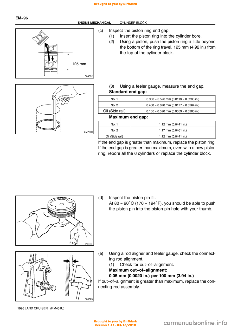
(c) Inspect the piston ring end gap.
(1) Insert the piston ring into the cylinder bore.
(2) Using a piston, push the piston ring a little beyondthe bottom of the ring travel, 125 mm (4.92 in.) from
the top of the cylinder block.
(3) Using a feeler gauge, measure the end gap.
Standard end gap:
No. 10.300 − 0.520 mm (0.0118 − 0.0205 in.)
No. 20.450 − 0.670 mm (0.0177 − 0.0264 in.)
Oil (Side rail)0.150 − 0.520 mm (0.0059 − 0.0205 in.)
Maximum end gap:
No. 11.12 mm (0.0441 in.)
No. 21.17 mm (0.0461 in.)
Oil (Side rail)1.12 mm (0.0441 in.)
If the end gap is greater than maximum, replace the piston ring.
If the end gap is greater than maximum, even with a new piston
ring, rebore all the 6 cylinders or replace the cylinder block.
(d) Inspect the piston pin fit.
At 80 − 90°C (176 − 194°F), you should be able to push
the piston pin into the piston pin hole with your thumb.
(e) Using a rod aligner and feeler gauge, check the connect- ing rod alignment.
(1) Check for out−of−alignment.
Maximum out−of−alignment:
0.05 mm (0.0020 in.) per 100 mm (3.94 in.)
If out− of−alignment is greater than maximum, replace the con-
necting rod assembly.
Brought to you by BirfMark
Brought to you by BirfMark
Version 1.11 - 03/16/2010