Page 823 of 1399
EM−38
−
ENGINE MECHANICAL CYLINDER HEAD
1996 LAND CRUISER (RM451U)
8. REMOVE NO. 1 AND NO. 2 ENGINE HANGERS
9. REMOVE 2 ENGINE WIRE CLAMP BRACKETS
Remove the 2 bolts and 2 wire clamp brackets.
10. REMOVE ACCELERATOR CABLE BRACKET AND
THROTTLE CABLE BRACKET
Remove the 2 bolts and 2 cable brackets.
11. REMOVE VALVE LIFTERS AND SHIMS
HINT:
Arrange the valve lifters and shims in correct order.
12. REMOVE VALVES
(a) Using SST, compress the valve spring and remove the 2 keepers.
SST 09202−70020 (09202 −00010)
(b) Remove the spring retainer, valve spring and valve.
(c) Using needle −nose pliers, remove the oil seal.
Brought to you by BirfMark
Brought to you by BirfMark
Version 1.11 - 03/16/2010
Page 825 of 1399
EM1Q7−01
EM−40
−
ENGINE MECHANICAL CYLINDER HEAD
1996 LAND CRUISER (RM451U)
INSPECTION
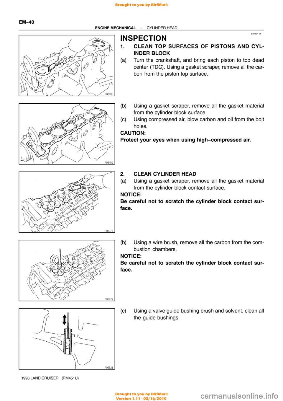
1. CLE AN TO P SURFACE S OF PIS TO NS AND CY L- INDER BLOCK
(a) Turn the crankshaft, and bring each piston to top dead center (TDC). Using a gasket scraper, remove all the car-
bon from the piston top surface.
(b) Using a gasket scraper, remove all the gasket material from the cylinder block surface.
(c) Using compressed air, blow carbon and oil from the bolt holes.
CAUTION:
Protect your eyes when using high −compressed air.
2. CLEAN CYLINDER HEAD
(a) Using a gasket scraper, remove all the gasket material from the cylinder block contact surface.
NOTICE:
Be careful not to scratch the cylinder block contact sur-
face.
(b) Using a wire brush, remove all the carbon from the com- bustion chambers.
NOTICE:
Be careful not to scratch the cylinder block contact sur-
face.
(c) Using a valve guide bushing brush and solvent, clean all the guide bushings.
Brought to you by BirfMark
Brought to you by BirfMark
Version 1.11 - 03/16/2010
Page 827 of 1399
Z00054
44.5°
EM0181
Margin Thickness
EM−42
−
ENGINE MECHANICAL CYLINDER HEAD
1996 LAND CRUISER (RM451U)
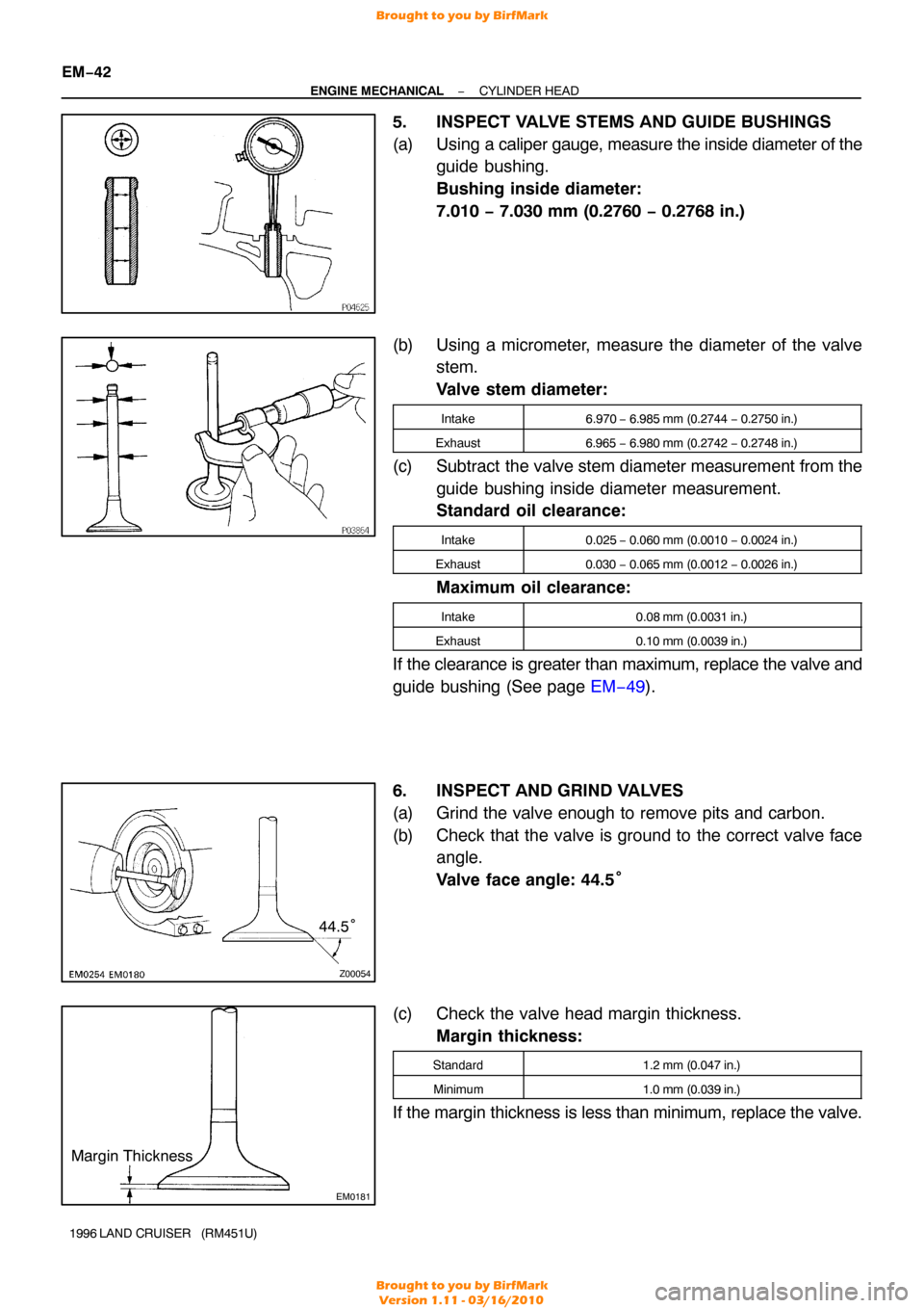
5. INSPECT VALVE STEMS AND GUIDE BUSHINGS
(a) Using a cali per gauge, measure the inside diameter of the
guide bushing.
Bushing inside diameter:
7.010 − 7.030 mm (0.2760 − 0.2768 in.)
(b) Using a micrometer, measure the diameter of the valve stem.
Valve stem diameter:
Intake6.970 − 6.985 mm (0.2744 − 0.2750 in.)
Exhaust6.965 − 6.980 mm (0.2742 − 0.2748 in.)
(c) Subtract the valve stem diameter measurement from the
guide bushing inside diameter measurement.
Standard oil clearance:
Intake0.025 − 0.060 mm (0.0010 − 0.0024 in.)
Exhaust0.030 − 0.065 mm (0.0012 − 0.0026 in.)
Maximum oil clearance:
Intake0.08 mm (0.0031 in.)
Exhaust0.10 mm (0.0039 in.)
If the clearance is greater than maximum, replace the valve and
guide bushing (See page EM−49).
6. INSPECT AND GRIND VALVES
(a) Grind the valve enough to remove pits and carbon.
(b) Check that the valve is ground to the correct valve face angle.
Valve face angle: 44.5°
(c) Check the valve head margin thickness. Margin thickness:
Standard1.2 mm (0.047 in.)
Minimum1.0 mm (0.039 in.)
If the margin thickness is less than minimum, replace the valve.
Brought to you by BirfMark
Brought to you by BirfMark
Version 1.11 - 03/16/2010
Page 830 of 1399
EM0281
P03976
P03977
−
ENGINE MECHANICAL CYLINDER HEAD
EM−45
1996 LAND CRUISER (RM451U)
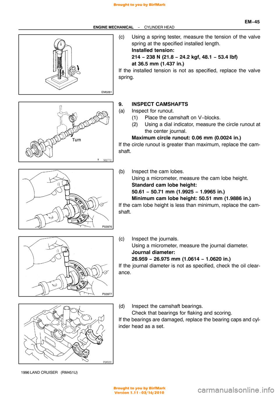
(c) Using a spring tester, measure the tension of the valve
spring at the specified installed length.
Installed tension:
214 − 238 N (21.8 − 24.2 kgf, 48.1 − 53.4 lbf)
at 36.5 mm (1.437 in.)
If the installed tension is not as specified, replace the valve
spring.
9. INSPECT CAMSHAFTS
(a) Inspect for runout. (1) Place the camshaft on V−blocks.
(2) Using a dial indicator, measure the circle runout atthe center journal.
Maximum circle runout: 0.06 mm (0.0024 in.)
If the circle runout is greater than maximum, replace the cam-
shaft.
(b) Inspect the cam lobes. Using a micrometer, measure the cam lobe height.
Standard cam lobe height:
50.61 − 50.71 mm (1.9925 − 1.9965 in.)
Minimum cam lobe height: 50.51 mm (1.9886 in.)
If the cam lobe height is less than minimum, replace the cam-
shaft.
(c) Inspect the journals. Using a micrometer, measure the journal diameter.
Journal diameter:
26.959 − 26.975 mm (1.0614 − 1.0620 in.)
If the journal diameter is not as specified, check the oil clear-
ance.
(d) Inspect the camshaft bearings. Check that bearings for flaking and scoring.
If the bearings are damaged, replace the bearing caps and cyl-
inder head as a set.
Brought to you by BirfMark
Brought to you by BirfMark
Version 1.11 - 03/16/2010
Page 831 of 1399
EM3322
EM−46
−
ENGINE MECHANICAL CYLINDER HEAD
1996 LAND CRUISER (RM451U)
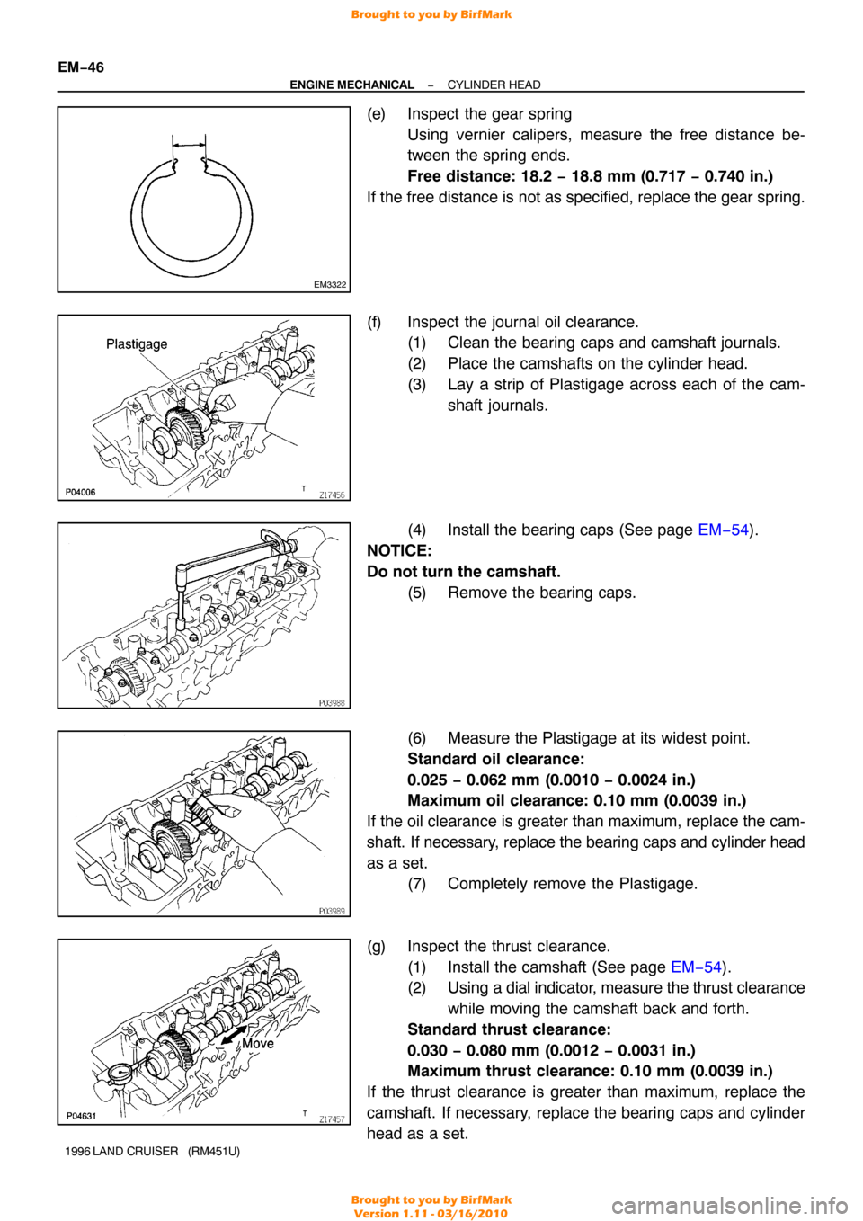
(e) Inspect the gear spring
Using vernier calipers, measure the free distance be-
tween the spring ends.
Free distance: 18.2 − 18.8 mm (0.717 − 0.740 in.)
If the free distance is not as specified, replace the gear spring.
(f) Inspect the journal oil clearance. (1) Clean the bearing caps and camshaft journals.
(2) Place the camshafts on the cylinder head.
(3) Lay a strip of Plastigage across each of the cam-
shaft journals.
(4) Install the bearing caps (See page EM−54).
NOTICE:
Do not turn the camshaft. (5) Remove the bearing caps.
(6) Measure the Plastigage at its widest point.
Standard oil clearance:
0.025 − 0.062 mm (0.0010 − 0.0024 in.)
Maximum oil clearance: 0.10 mm (0.0039 in.)
If the oil clearance is greater than maximum, replace the cam-
shaft. If necessary, replace the bearing caps and cylinder head
as a set. (7) Completely remove the Plastigage.
(g) Inspect the thrust clearance. (1) Install the camshaft (See page EM−54 ).
(2) Using a dial indicator, measure the thrust clearance
while moving the camshaft back and forth.
Standard thrust clearance:
0.030 − 0.080 mm (0.0012 − 0.0031 in.)
Maximum thrust clearance: 0.10 mm (0.0039 in.)
If the thrust clearance is greater than maximum, replace the
camshaft. If necessary, replace the bearing caps and cylinder
head as a set.
Brought to you by BirfMark
Brought to you by BirfMark
Version 1.11 - 03/16/2010
Page 832 of 1399
EM2196
−
ENGINE MECHANICAL CYLINDER HEAD
EM−47
1996 LAND CRUISER (RM451U)
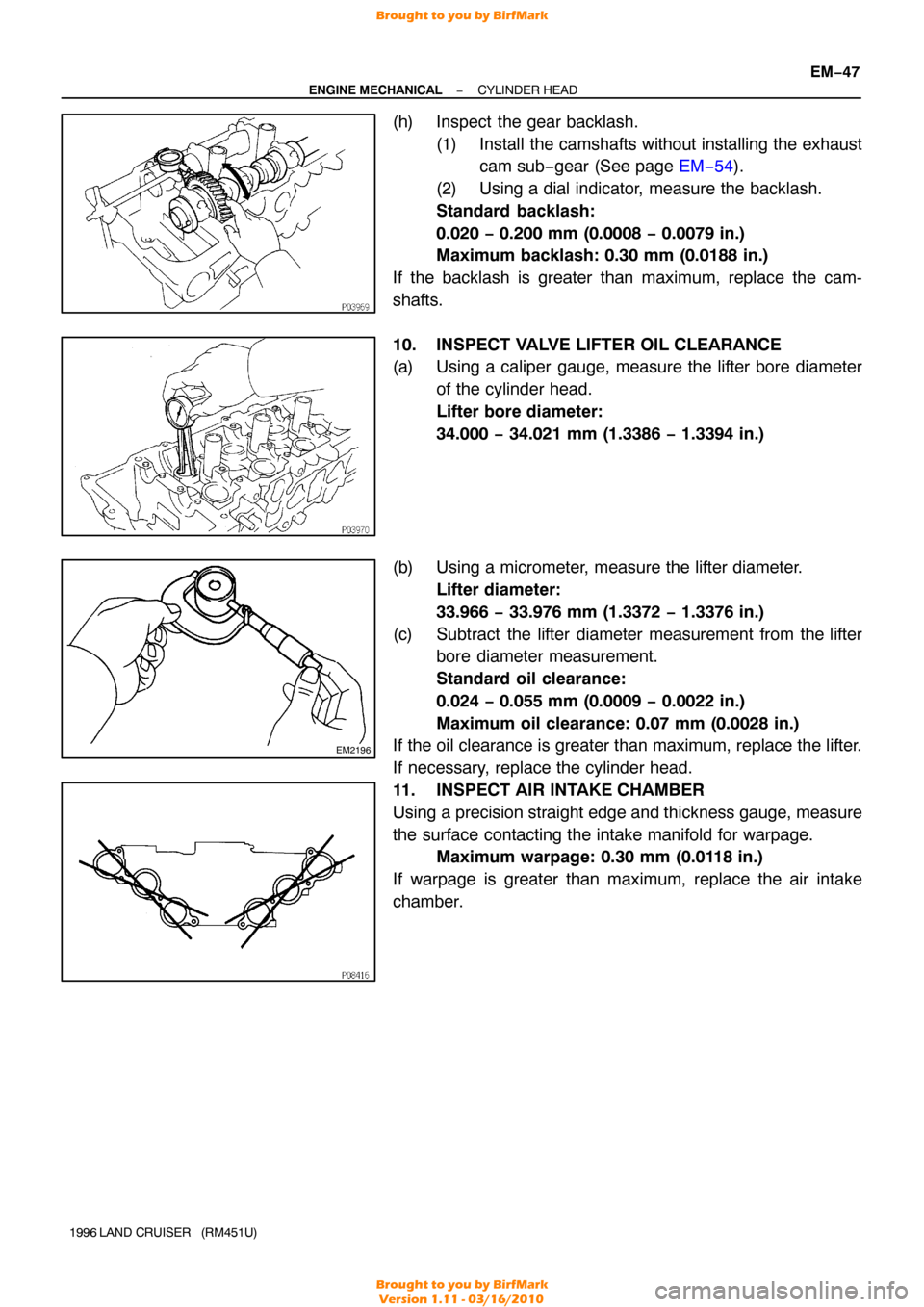
(h) Inspect the gear backlash.
(1) Install the camshafts without installing the exhaustcam sub−gear (See page EM−54).
(2) Using a dial indicator, measure the backlash.
Standard backlash:
0.020 − 0.200 mm (0.0008 − 0.0079 in.)
Maximum backlash: 0.30 mm (0.0188 in.)
If the backlash is greater than maximum, replace the cam-
shafts.
10. INSPECT VALVE LIFTER OIL CLEARANCE
(a) Using a caliper gauge, measure the lifter bore diameter of the cylinder head.
Lifter bore diameter:
34.000 − 34.021 mm (1.3386 − 1.3394 in.)
(b) Using a micrometer, measure the lifter diameter. Lifter diameter:
33.966 − 33.976 mm (1.3372 − 1.3376 in.)
(c) Subtract the lifter diameter measurement from the lifter bore diameter measurement.
Standard oil clearance:
0.024 − 0.055 mm (0.0009 − 0.0022 in.)
Maximum oil clearance: 0.07 mm (0.0028 in.)
If the oil clearance is greater than maximum, replace the lifter.
If necessary, replace the cylinder head.
11. INSPECT AIR INTAKE CHAMBER
Using a precision straight edge and thickness gauge, measure
the surface contacting the intake manifold for warpage. Maximum warpage: 0.30 mm (0.0118 in.)
If warpage is greater than maximum, replace the air intake
chamber.
Brought to you by BirfMark
Brought to you by BirfMark
Version 1.11 - 03/16/2010
Page 836 of 1399
EM1E6−01
−
ENGINE MECHANICAL CYLINDER HEAD
EM−51
1996 LAND CRUISER (RM451U)
REASSEMBLY
HINT:
�Thoroughly clean all parts to be assembled.
�Before installing the parts, apply new engine oil to all slid-
ing and rotating surfaces.
�Replace all gaskets and oil seals with new ones.
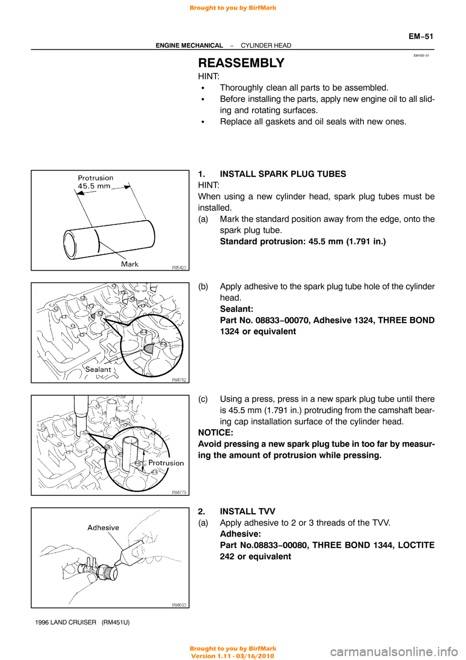
1. INSTALL SPARK PLUG TUBES
HINT:
When using a new cylinder head, spark plug tubes must be
installed.
(a) Mark the standard position away from the edge, onto the spark plug tube.
Standard protrusion: 45.5 mm (1.791 in.)
(b) Apply adhesive to the spark plug tube hole of the cylinder
head.
Sealant:
Part No. 08833−00070, Adhesive 1324, THREE BOND
1324 or equivalent
(c) Using a press, press in a new spark plug tube until there is 45.5 mm (1.791 in.) protruding from the camshaft bear-
ing cap installation surface of the cylinder head.
NOTICE:
Avoid pressing a new spark plug tube in too far by measur-
ing the amount of protrusion while pressing.
2. INSTALL TVV
(a) Apply adhesive to 2 or 3 threads of the TVV. Adhesive:
Part No.08833 −00080, THREE BOND 1344, LOCTITE
242 or equivalent
Brought to you by BirfMark
Brought to you by BirfMark
Version 1.11 - 03/16/2010
Page 837 of 1399
EM−52
−
ENGINE MECHANICAL CYLINDER HEAD
1996 LAND CRUISER (RM451U)
(b) Install the TVV.
3. INSTALL ECT SENDER GAUGE
4. INSTALL ECT CUT SWITCH
5. INSTALL ECT SENSOR
6. INSTALL VALVES
(a) Using SST, push in a new oil seal.
SST 09236−00101 (09236 −15010)
HINT:
Different oil seals are used for the intake and exhaust.
(b) Install the valve (1), spring seat (2), valve spring (3) and spring retainer (4).
(c) Using SST, compress the valve spring and place the 2 keepers around the valve stem.
SST 09202−70020 (09202 −00010)
Brought to you by BirfMark
Brought to you by BirfMark
Version 1.11 - 03/16/2010