Page 466 of 2890

2. Engine Noise
Valve lash adjusters may make clicking noise once engine
starts. It is normal if clicking noise ceases after a few min-
utes.
If clicking noise continues for more than a few minutes,
inspect Hydraulic Lash Adjuster (HLA) in accordance with
the following flow chart.
Inspect the engine oil level
(1) Adjust the oil level between“F”and“L”.
(2) Replace the oil when deteriorated.
Load less engine operation to bleed air from
HLA.
(1) Warm-up engine for about five minutes.
(2) If the noise is remaining, keep the engine
running at 2,000 rpm for up to 20 minutes until
the noise fades away.�Noise is eliminated.
Keep the engine running at 2,500 rpm for about
five minutes to bleed air completely.
Noise remains or comes
back.END
HLA is rigid and has no valve clearance.
Remove the rocker cover and inspect HLA.
Press HLA while it is facing the base circle of
the cam.
�HLA is normal. The noise may come from other
sources.
HLA is not rigid.
There is valve clearance.
Check whether the clearance between HLA and
the bushing of the cylinder head is within
allowance or not.
HLA is seized. Replace HLA.
�Out of allowance
Replace the cylinder head related parts or the
HLA, whichever is necessary.
Within allowance
Replace HLA.
�
�
�
�
�
�
78
2-3bDIAGNOSTICS
2. Engine Noise
Page 467 of 2890

If noise still exists, conduct diagnostics procedures in
accordance with the following table.
CAUTION:
Do not disconnect spark plug cord while engine is run-
ning.
Type of sound Condition Possible cause
Regular clicking soundSound increases as engine
speed increases.Valve mechanism is defective.
�Broken lash adjuster
�Worn camshaft
�Broken valve spring
�Worn valve lifter hole
Heavy and dull clankOil pressure is low.�Worn crankshaft main bearing
�Worn connecting rod bearing (big end)
Oil pressure is normal.�Loose flywheel mounting bolts
�Damaged engine mounting
High-pitched clank
(Spark knock)Sound is noticeable when
accelerating with an overload.�Ignition timing advanced
�Accumulation of carbon inside combustion chamber
�Wrong spark plug
�Improper gasoline
Clank when engine speed is
medium (1,000 to 2,000 rpm).Sound is reduced when fuel
injector connector of noisy
cylinder is disconnected.
(NOTE*)�Worn crankshaft main bearing
�Worn bearing at crankshaft end of connecting rod
Knocking sound when engine
is operating under idling speed
and engine is warm.Sound is reduced when fuel
injector connector of noisy
cylinder is disconnected.
(NOTE*)�Worn cylinder liner and piston ring
�Broken or stuck piston ring
�Worn piston pin and hole at piston end of connecting rod
Sound is not reduced if each
fuel injector connector is
disconnected in turn. (NOTE*)�Unusually worn valve lifter
�Worn cam gear
�Worn camshaft journal bore in crankcase
Squeaky sound—�Insufficient generator lubrication
Rubbing sound—�Defective generator brush and rotor contact
Gear scream when starting
engine—�Defective ignition starter switch
�Worn gear and starter pinion
Sound like polishing glass with
a dry cloth—�Loose drive belt
�Defective engine coolant pump shaft
Hissing sound—�Loss of compression
�Air leakage in air intake system, hoses, connections or
manifolds
Timing belt noise—�Loose timing belt
�Belt contacting case/adjacent part
NOTE*:
When disconnecting fuel injector connector, Malfunction Indicator Light (CHECK ENGINE light) illuminates and trouble code is stored in
ECM memory.
Therefore, carry out the CLEAR MEMORY MODE and INSPECTION MODE after connecting fuel injector connector. (Ref. to 2-7 On-Board
Diagnostics II System.)
79
2-3bDIAGNOSTICS
2. Engine Noise
Page 477 of 2890
G2M0082
15) Separate oil strainer from oil strainer stay.
G2M0376
16) Remove oil strainer.
G2M0377
17) Remove baffle plate and oil strainer stay.
B: INSPECTION
By visual check make sure oil pan, oil strainer, oil strainer
stay and baffle plate are not damaged.
G2M0377
C: INSTALLATION
CAUTION:
Before installing oil pan, clean sealant from oil and
engine block.
1) Install baffle plate and oil strainer stay.
Tightening torque:
5N⋅m (0.5 kg-m, 3.6 ft-lb)
11
2-4SERVICE PROCEDURE
2. Oil Pan and Oil Strainer
Page 484 of 2890
 O")
1. Engine Lubrication System
Before troubleshooting, make sure that the engine oil level
is correct and no oil leakage exists.
Trouble Possible cause Corrective action
1. Warning light remains
on.1) Oil pressure switch
failureCracked diaphragm or oil leakage within switch Replace.
Broken spring or seized contacts Replace.
2) Low oil pressureClogged oil filter Replace.
Malfunction of oil by-pass valve of oil filter Clean or replace.
Malfunction of oil relief valve of oil pump Clean or replace.
Clogged oil passage Clean.
Excessive tip clearance and side clearance of oil
pump rotor and gearReplace.
Clogged oil strainer or broken pipe Clean or replace.
3) No oil pressureInsufficient engine oil Replenish.
Broken pipe of oil strainer Replace.
Stuck oil pump rotor Replace.
2. Warning light does not
go on.1) Burn-out bulb Replace.
2) Poor contact of switch contact points Replace.
3) Disconnection of wiring Repair.
3. Warning light flickers
momentarily.1) Poor contact at terminals Repair.
2) Defective wiring harness Repair.
3) Low oil pressureCheck for the same pos-
sible causes as listed in
1.—2)
17
2-4DIAGNOSTICS
1. Engine Lubrication System
Page 491 of 2890
 Fill engine coolant into reservoir tank up to upper level.
4) Attach radiator cap and reservoir tank cap properly.
5) Install air vent plug.
6) Warm-up engine completely for more than five")
B2M0140
3) Fill engine coolant into reservoir tank up to upper level.
4) Attach radiator cap and reservoir tank cap properly.
5) Install air vent plug.
6) Warm-up engine completely for more than five minutes
at 2,000 to 3,000 rpm.
7) Stop engine and wait until temperature drops to a safe
level.
8) If engine coolant level drops in radiator, add engine
coolant to filler neck position.
9) If engine coolant level drops from upper level of reser-
voir tank, add engine coolant to upper level.
10) Attach radiator cap and reservoir tank cap properly.
B2M0136
C: CHECKING OF COOLING SYSTEM
1) Remove radiator cap, top off radiator, and attach tester
to radiator in place of cap.
2) Apply a pressure of 157 kPa (1.6 kg/cm
2, 23 psi) to
radiator to check if:
(1) Engine coolant leaks at/around radiator.
(2) Engine coolant leaks at/around hoses or connec-
tions.
CAUTION:
�Engine should be off.
�Wipe engine coolant from check points in advance.
�Be careful to prevent engine coolant from spurting
out when removing tester.
�Be careful also not to deform filler neck of radiator
when installing or removing tester.
8
2-5SERVICE PROCEDURE
1. On-Car Service
Page 494 of 2890
G2M0210
12) Remove tensioner bracket.
13) Disconnect heater hose from engine coolant pump.
14) Remove engine coolant pump.
B: INSPECTION
1) Check engine coolant pump bearing for smooth rota-
tion.
2) Check engine coolant pump pulley for abnormalities.
G2M0211
3) Using a dial gauge, measure impeller runout in thrust
direction while rotating the pulley.
“Thrust”runout limit:
0.5 mm (0.020 in)
G2M0212
4) Check clearance between impeller and pump case.
Clearance between impeller and pump case:
Standard
0.5—0.7 mm (0.020—0.028 in)
Limit
1.0 mm (0.039 in)
5) After engine coolant pump installation, check pulley
shaft for engine coolant leaks. If leaks are noted, replace
engine coolant pump assembly.
11
2-5SERVICE PROCEDURE
2. Engine Coolant Pump
Page 505 of 2890

CONDITION:
�Engine coolant temperature is above 95°C (203°F).
TROUBLE SYMPTOM:
�Radiator main fan does not operate under the above
condition.
1. Check fuse and power")
A: OPERATION (WITHOUT A/C MODEL)
CONDITION:
�Engine coolant temperature is above 95°C (203°F).
TROUBLE SYMPTOM:
�Radiator main fan does not operate under the above
condition.
1. Check fuse and power supply.
OK
�Not OK
Melted fuse,repair the shorted part of the circuit
,replace fuse.
2. Check harness connector between fuse and
relay box, and A/C relay holder.
OK
�Not OK
Repair or replace wiring harness.
3. Check A/C relay holder.
OK
�Not OK
Repair or replace A/C relay holder.
4. Check harness connector between A/C relay
holder and main fan motor.
OK
�Not OK
Repair or replace wiring harness.
5. Check ground circuit of main fan motor.
OK
�Not OK
Repair or replace wiring harness.
6. Check main fan motor.
OK
�Not OK
Replace main fan motor.
Refer to 2-7 On-Board Diagnostics II System.
B2M0427A
1. CHECK FUSE AND POWER SUPPLY.
1) Check fuse No. 13.
2) Turn ignition switch to ACC.
3) Measure voltage between fuse and relay box, and body.
Connector & terminal / Specified voltage:
(F40) No. 3—Body / 10 V, or more
�
�
�
�
�
�
22
2-5DIAGNOSTICS
2. Radiator Main Fan
Page 507 of 2890
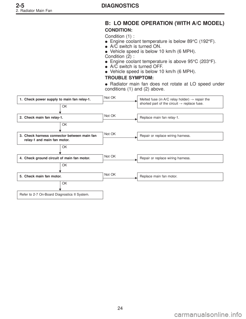
B: LO MODE OPERATION (WITH A/C MODEL)
CONDITION:
Condition (1) :
�Engine coolant temperature is below 89°C (192°F).
�A/C switch is turned ON.
�Vehicle speed is below 10 km/h (6 MPH).
Condition (2) :
�Engine coolant temperature is above 95°C (203°F).
�A/C switch is turned OFF.
�Vehicle speed is below 10 km/h (6 MPH).
TROUBLE SYMPTOM:
�Radiator main fan does not rotate at LO speed under
conditions (1) and (2) above.
1. Check power supply to main fan relay-1.
OK
�Not OK
Melted fuse (in A/C relay holder),repair the
shorted part of the circuit,replace fuse.
2. Check main fan relay-1.
OK
�Not OK
Replace main fan relay-1.
3. Check harness connector between main fan
relay-1 and main fan motor.
OK
�Not OK
Repair or replace wiring harness.
4. Check ground circuit of main fan motor.
OK
�Not OK
Repair or replace wiring harness.
5. Check main fan motor.
OK
�Not OK
Replace main fan motor.
Refer to 2-7 On-Board Diagnostics II System.
�
�
�
�
�
24
2-5DIAGNOSTICS
2. Radiator Main Fan
 Separate oil strainer from oil strainer stay.
G2M0376
16) Remove oil strainer.
G2M0377
17) Remove baffle plate and oil strainer stay.
B: INSPECTION
By visual check make sure oil pan, oil s")
 Remove tensioner bracket.
13) Disconnect heater hose from engine coolant pump.
14) Remove engine coolant pump.
B: INSPECTION
1) Check engine coolant pump bearing for smooth rota-
tion.
2)")