Page 1120 of 2890
 Insert combination switch to upper column shaft, and
install lower column cover with tilt lever held in the lowered
position. Then route ignition key harness and combination
swi")
B4M0555
D: ASSEMBLY
1) Insert combination switch to upper column shaft, and
install lower column cover with tilt lever held in the lowered
position. Then route ignition key harness and combination
switch harness between column cover mounting bosses.
2) Fit upper column cover to lower column cover, and
tighten combination switch and column cover.
Tightening torque:
1.2±0.2 N⋅m (0.12±0.02 kg-m, 0.9±0.1 ft-lb)
CAUTION:
Don’t overtorque screw.
E: INSTALLATION
1) Insert end of steering shaft into toe board grommet.
2) Tighten steering shaft mounting bolts under instrument
panel.
Tightening torque:
25±5 N⋅m (2.5±0.5 kg-m, 18.1±3.6 ft-lb)
3) Connect ignition and combination switch connectors
under instrument panel.
4) Connect airbag system connector at harness spool.
NOTE:
Make sure to apply double lock.
5) Install universal joint.
(1) Align bolt hole on the long yoke side of universal
joint with the cutout at the serrated section of shaft end,
and insert universal joint.
(2) Align bolt hole on the short yoke side of universal
joint with the cutout at the serrated section of gearbox
assembly. Lower universal joint completely.
(3) Temporarily tighten bolt on the short yoke side.
Raise universal joint to make sure the bolt is properly
passing through the cutout at the serrated section.
(4) Tighten bolt on the long yoke side, then that on the
short yoke side.
Tightening torque:
24±3 N⋅m (2.4±0.3 kg-m, 17.4±2.2 ft-lb)
CAUTION:
�Make sure that universal joint bolts is tightened
through notch in shaft serration.
�Excessively large tightening torque of universal
joint bolts may lead to heavy steering wheel operation.
Standard clearance between gearbox to DOJ:
Over 15 mm (0.59 in)
13
4-3SERVICE PROCEDURE
2. Tilt Steering Column
Page 1121 of 2890
G5M0328
6) Align center of roll connector. (with airbag model)
CAUTION:
Ensure that front wheels are set in straight-forward
direction.
7) Set steering wheel to neutral and install it onto steering
shaft.
Tightening torque:
34±5 N⋅m (3.5±0.5 kg-m, 25.3±3.6 ft-lb)
Column cover-to-steering wheel clearance:
2 — 4 mm (0.08 — 0.16 in)
CAUTION:
Insert roll connector guide pin into guide hole on lower
end of surface of steering wheel to prevent damage.
Draw out airbag system connector, horn connector
and cruise control connectors from guide hole of
steering wheel lower end. (with airbag model)
8) Install airbag module to steering wheel. (with airbag
model)
WARNING:
Always refer to 5-5 [W3B1] before performing the ser-
vice operation.
14
4-3SERVICE PROCEDURE
2. Tilt Steering Column
Page 1133 of 2890
 How to install the joint.
(1) Push the long yoke of the joint, all the way into the
serrated portion of the steering shaft, setting the bolt
hole in the cutout.
(2) Then pull the short yoke all way")
3) How to install the joint.
(1) Push the long yoke of the joint, all the way into the
serrated portion of the steering shaft, setting the bolt
hole in the cutout.
(2) Then pull the short yoke all way out of the serrated
portion of the gearbox, setting the bolt hole in the cut-
out.
(3) Insert the bolt through the short yoke, pull the joint
and confirm that the bolt is on cutout of the gearbox.
G4M0086
(4) Fasten the short yoke side with a spring washer
and bolt, then fasten the long yoke side.
Tightening torque:
24±3 N⋅m (2.4±0.3 kg-m, 17.4±2.2 ft-lb)
G4M0097
4) Connect tie-rod end and knuckle arm, and tighten with
castle nut. Fit cotter pin into the nut and bend the pin to
lock.
Castle nut tightening torque:
Tighten to 27.0±2.5 N⋅m (2.75±0.25 kg-m,
19.9±1.8 ft-lb), and tighten further within 60°until
cotter pin hole is aligned with a slot in the nut.
CAUTION:
When connecting, do not hit cap at the bottom of tie-
rod end with hammer.
5) Install front stabilizer to vehicle.
6) Install front exhaust pipe assembly.
7) Install tires.
8) Tighten wheel nuts to the specified torque.
Tightening torque:
88±10 N⋅m (9.0±1.0 kg-m, 65±7 ft-lb)
9) Connect ground cable to battery.
10) Pour fluid into oil tank, and bleed air.
[W10A0].>
11) Check for fluid leaks.
12) Install jack-up plate.
WARNING:
Be careful, exhaust manifold is hot.
13) Lower vehicle.
14) Check fluid level in oil tank.
26
4-3SERVICE PROCEDURE
3. Steering Gearbox (Power Steering System) [LHD model]
Page 1134 of 2890
G4M0132
15) After adjusting toe-in and steering angle, tighten lock
nut on tie-rod end.
Tightening torque:
83±5 N⋅m (8.5±0.5 kg-m, 61.5±3.6 ft-lb)
CAUTION:
When adjusting toe-in, hold boot as shown to prevent
it from being rotated or twisted. If twisted, straighten it.
G4M0133
F: ADJUSTMENT
1) Adjust front toe.
Standard of front toe:
IN 3—OUT 3 mm (IN 0.12—OUT 0.12 in)
2) Adjust steering angle of wheels.
Inner wheel: 37.6°±1.5
Outer wheel: 32.6°±1.5
B4M0133A
3) If steering wheel spokes are not horizontal when wheels
are set in the straight ahead position, and error is more
than 5°on the periphery of steering wheel, correctly re-in-
stall the steering wheel.
G4M0135
4) If steering wheel spokes are not horizontal with vehicle
set in the straight ahead position after this adjustment,
correct it by turning the right and left tie-rods in the same
direction by the same turns.
27
4-3SERVICE PROCEDURE
3. Steering Gearbox (Power Steering System) [LHD model]
Page 1189 of 2890
 Check the fluid leakage at flare nuts after turning
steering wheel from lock to lock with engine running.
CAUTION:
�Before checking, wipe off any fluid on flare nuts and
piping.
�In case the fluid")
10) Check the fluid leakage at flare nuts after turning
steering wheel from lock to lock with engine running.
CAUTION:
�Before checking, wipe off any fluid on flare nuts and
piping.
�In case the fluid leaks from flare nut, it is caused by
dust (or the like) and/or damage between flare and
tapered seat in piping.
�So remove the flare nut, tighten again it to the speci-
fied torque after cleaning flare and tapered seat. If flare
or tapered seat is damaged, replace it with a new one.
11) Inspect fluid level on flat and level surface with engine
“OFF”by indicator of filler cap.
If the level is at lower point or below, add fluid to keep the
level in the specified range of the indicator. If at upper point
or above, drain fluid by using a syringe or the like.
Fluid capacity:
0.7�(0.7 US qt, 0.6 Imp qt)
B4M0563
(1) Check at temperature 21°C (70°F) on reservoir sur-
face of oil pump.
(2) Check at temperature 60°C (140°F) on reservoir
surface of oil pump.
82
4-3SERVICE PROCEDURE
10. Power Steering Fluid
Page 1193 of 2890
 or less in both directions
GOOD
�NOT GOOD
Adjust backl")
3. MEASUREMENT OF STEERING EFFORT
*4
Measure steering efforts in stand still with engine idling on
concrete road.
Result: 29.4 N (3.0 kg, 6.6 lb) or less in both directions
GOOD
�NOT GOOD
Adjust backlash.
Measure steering efforts in stand still with engine stalled on
concrete road.
Result: 294.2 N (30.0 kg, 66.2 lb) or less in both directions
NOT GOOD GOOD*4 When turning steering more
quickly than necessary from
a direction to the other direc-
tion at an engine speed over
2,000 rpm, steering effort
may be heavy. This is caused
by flow characteristic of oil
pump and is not a problem.
Adjust backlash.
Remove universal joint.
Measure steering wheel effort.
Result: Maximum force is 2.26 N (0.23 kg, 0.51 lb) or less in
both directions.
Fluctuation width is 1.08 N (0.11 kg, 0.24 lb) or less.
GOOD
�NOT GOOD
Check, readjust, replace if
necessary.
Measure folding torque of the joint.
Result: 5.49 N (0.56 kg, 1.23 lb) or less for long yoke
8.43 N (0.86 kg, 1.90 lb) or less for short yoke
GOOD
�NOT GOOD
Replace with a new one.
Check front wheels for unsteady revolution or rattling and brake
for dragging.
GOOD
�NOT GOOD
Inspect, readjust, replace if
necessary.
Remove tie-rod ends.
(To be continued.)
�
�
�
�
�
�
�
�
86
4-3DIAGNOSTICS
1. Power Steering
Page 1203 of 2890

While engine is running with/
without steering turned.Loosened installation of oil pump,
oil pump bracketRetighten.
*8
Abnormal inside of oil pump, hoseRepl")
Whine or growl (continuous or
intermittent)
While engine is running with/
without steering turned.Loosened installation of oil pump,
oil pump bracketRetighten.
*8
Abnormal inside of oil pump, hoseReplace oil pump, hose, if the
noise can be heard when running
as well as stand still.
Torque converter growl
air conditioner compression growlRemove power steering pulley
belt and confirm.
Creaking noise (intermittent)
While engine is running with
steering turned.Abnormal inside of gearboxReplace bad parts of gearbox.
Abnormal bearing for steering
shaftApply grease or replace.
*9
Generates when turning steering
wheel with brake (service or park-
ing) applied.If the noise goes off when brake
is released, it is normal.
*10
Vibration
While engine is running with/
without steering turned.
Too low engine speed at startAdjust and instruct customers.
Vane pump aerationFix wrong part.
Vent air.
Damaged valve in oil pump, gear-
boxReplace oil pump, bad parts of
gearbox.
Looseness of play of steering,
suspension partsRetighten.
*8 Oil pump makes whine or growl noise slightly due to its mechanism. Even if the noise can be heard when steering wheel
is turned at stand still there is no abnormal function in the system provided that the noise eliminates when the vehicle is
running.
*9 When stopping with service brake and/or parking brake applied, power steering can be operated easily due to its light
steering effort. If doing so, the disk rotates slightly and makes creaking noise. The noise is generated by creaking between
the disk and pads. If the noise goes off when the brake is released, there is no abnormal function in the system.
*10 There may be a little vibration around the steering devices when turning steering wheel at standstill, even though the com-
ponent parts are properly adjusted and have no defects.
Hydraulic systems are likely to generate this kind of vibration as well as working noise and fluid noise because of com-
bined conditions, i.e., road surface and tire surface, engine speed and turning speed of steering wheel, fluid temperature
and braking condition.
This phenomena does not indicate there is some abnormal function in the system.
The vibration can be known when steering wheel is turned repeatedly at various speeds from slow to rapid step by step
with parking brake applied on concrete road and in“D”range for automatic transmission vehicle.
96
4-3DIAGNOSTICS
1. Power Steering
Page 1217 of 2890
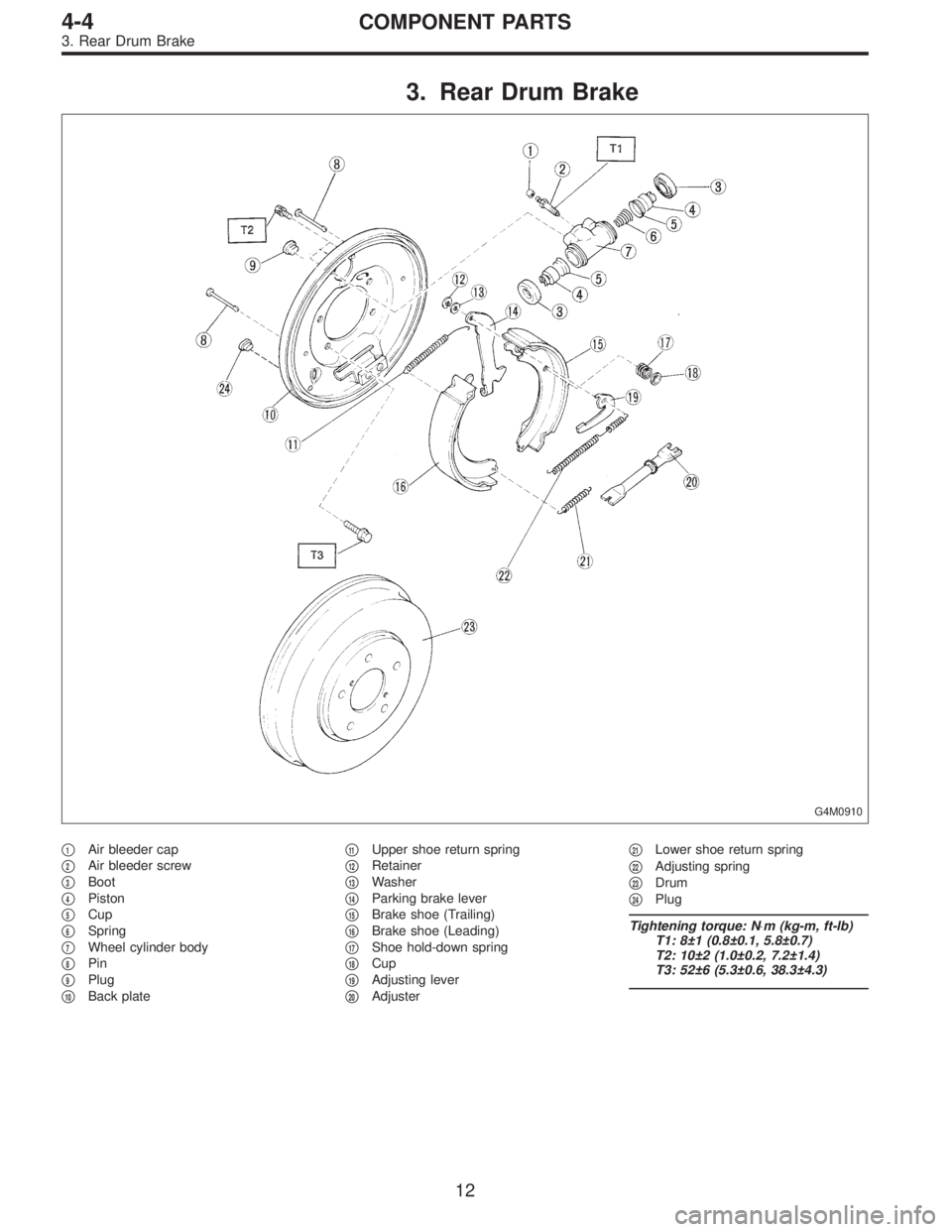
3. Rear Drum Brake
G4M0910
�1Air bleeder cap
�
2Air bleeder screw
�
3Boot
�
4Piston
�
5Cup
�
6Spring
�
7Wheel cylinder body
�
8Pin
�
9Plug
�
10Back plate�
11Upper shoe return spring
�
12Retainer
�
13Washer
�
14Parking brake lever
�
15Brake shoe (Trailing)
�
16Brake shoe (Leading)
�
17Shoe hold-down spring
�
18Cup
�
19Adjusting lever
�
20Adjuster�
21Lower shoe return spring
�
22Adjusting spring
�
23Drum
�
24Plug
Tightening torque: N⋅m (kg-m, ft-lb)
T1: 8±1 (0.8±0.1, 5.8±0.7)
T2: 10±2 (1.0±0.2, 7.2±1.4)
T3: 52±6 (5.3±0.6, 38.3±4.3)
12
4-4COMPONENT PARTS
3. Rear Drum Brake
![SUBARU LEGACY 1996 Service Repair Manual G5M0328
6) Align center of roll connector. (with airbag model)
<Ref. to 5-5 [W7B1].>
CAUTION:
Ensure that front wheels are set in straight-forward
direction.
7) Set steering wheel to neutral and insta](/manual-img/17/57433/w960_57433-1120.png "SUBARU LEGACY 1996 Service Repair Manual G5M0328
6) Align center of roll connector. (with airbag model)
<Ref. to 5-5 [W7B1].>
CAUTION:
Ensure that front wheels are set in straight-forward
direction.
7) Set steering wheel to neutral and insta")
 After adjusting toe-in and steering angle, tighten lock
nut on tie-rod end.
Tightening torque:
83±5 N⋅m (8.5±0.5 kg-m, 61.5±3.6 ft-lb)
CAUTION:
When adjusting toe-in, hold boot as sho")