Page 1078 of 2890

CAUTION:
�Use a new axle nut.
�Always tighten axle nut before installing wheel on
vehicle. If wheel is installed and comes in contact with")
Tightening torque:
186±20 N⋅m (19±2 kg-m, 137±14 ft-lb)
CAUTION:
�Use a new axle nut.
�Always tighten axle nut before installing wheel on
vehicle. If wheel is installed and comes in contact with
ground when axle nut is loose, wheel bearings may be
damaged.
�Be sure to tighten axle nut to specified torque. Do
not overtighten it as this may damage wheel bearing.
12) Install O-ring to hub cap flange, and install hub cap by
lightly tapping it with a plastic-faced hammer.
13) Install wheel and tighten wheel nuts to specified
torque.
Tightening torque (Wheel nut):
88±10 N⋅m (9±1 kg-m, 65±7 ft-lb)
4. Front and Rear Drive Shafts
A: REMOVAL
1. FRONT DRIVE SHAFT
1) Disconnect ground cable from battery.
2) Jack-up vehicle, support it with safety stands (rigid
racks), and remove front wheel cap and wheels.
3) Unlock axle nut.
4) While depressing brake pedal, remove axle nut using a
socket wrench.
CAUTION:
Be sure to loosen and retighten axle nut after remov-
ing wheel from vehicle. Failure to follow this rule may
damage wheel bearings.
5) Disconnect stabilizer link from transverse link.
6) Disconnect transverse link from housing.
G4M0279
7) Remove spring pin which secures transmission spindle
to DOJ.
CAUTION:
Use a new spring pin.
28
4-2SERVICE PROCEDURE
3. Rear Axle (FWD) - 4. Front and Rear Drive Shafts
Page 1094 of 2890
 Install DOJ on transmission spindle and drive spring pin
into place.
CAUTION:
Always use a new spring pin.
5) Connect transverse link to housing.
Tightening torque (self-locking nut):
49±1")
G4M0279
4) Install DOJ on transmission spindle and drive spring pin
into place.
CAUTION:
Always use a new spring pin.
5) Connect transverse link to housing.
Tightening torque (self-locking nut):
49±10 N⋅m (5.0±1.0 kg-m, 36±7 ft-lb)
CAUTION:
Use a new self-locking nut.
6) Install stabilizer bracket.
7) While depressing brake pedal, tighten axle nut to the
specified torque.
Tightening torque:
186±20 N⋅m (19±2 kg-m, 137±14 ft-lb)
CAUTION:
�Use a new axle nut.
�Always tighten axle nut before installing wheel on
vehicle. If wheel is installed and comes in contact with
ground when axle nut is loose, wheel bearings may be
damaged.
�Be sure to tighten axle nut to specified torque. Do
not overtighten it as this may damage wheel bearing.
8) After tightening axle nut, lock it securely.
G4M0293
2. REAR DRIVE SHAFT
1) Insert BJ into rear housing splines.
CAUTION:
Be careful not to damage inner oil seal lip.
2) Using ST1 and ST2, pull drive shaft into place.
ST1 922431000 AXLE SHAFT INSTALLER
ST2 927390000 ADAPTER
CAUTION:
Do not hammer drive shaft when installing it.
3) Tighten axle nut temporarily.
B4M0549A
4) Using ST, install DOJ into differential.
ST 28099PA090 SIDE OIL SEAL PROTECTOR
44
4-2SERVICE PROCEDURE
4. Front and Rear Drive Shafts
Page 1095 of 2890
 Insert DOJ spline end into bore of side oil seal, and
remove ST.
CAUTION:
Do not allow DOJ splines to damage side oil seal.
ST 28099PA090 SIDE OIL SEAL PROTECTOR
G3M0050
6) Align DOJ and d")
B4M0550A
5) Insert DOJ spline end into bore of side oil seal, and
remove ST.
CAUTION:
Do not allow DOJ splines to damage side oil seal.
ST 28099PA090 SIDE OIL SEAL PROTECTOR
G3M0050
6) Align DOJ and differential splines.
7) Push housing to insert DOJ into differential.
NOTE:
Make sure DOJ is inserted properly.
8) Connect crossmember reinforcement lower to cross-
member (4 door model only).
9) Connect rear housing assembly to trailing link
assembly, and tighten self-locking nut.
Tightening torque:
113±15 N⋅m (11.5±1.5 kg-m, 83±11 ft-lb)
10) Connect rear housing assembly to lateral link
assembly, and tighten self-locking nut.
Tightening torque:
137±20 N⋅m (14±2 kg-m, 101±14 ft-lb)
11) Install stabilizer bracket.
12) While depressing brake pedal, tighten axle nut using
a socket wrench.
Tightening torque:
186±20 N⋅m (19±2 kg-m, 137±14 ft-lb)
CAUTION:
�Use a new axle nut.
�Always tighten axle nut before installing wheel on
vehicle. If wheel is installed and comes in contact with
ground when axle nut is loose, wheel bearings may be
damaged.
�Be sure to tighten axle nut to specified torque. Do
not overtighten it as this may damage wheel bearing.
13) After tightening axle nut, lock it securely.
45
4-2SERVICE PROCEDURE
4. Front and Rear Drive Shafts
Page 1103 of 2890
 Proper wheel balance may be lost if the tire is repaired
or if it wears. Check the tire for dynamic balance, and repair
as necessary.
2) To check for dynamic balance, u")
B4M0053A
10. Wheel Balancing
1) Proper wheel balance may be lost if the tire is repaired
or if it wears. Check the tire for dynamic balance, and repair
as necessary.
2) To check for dynamic balance, use a dynamic balancer.
Drive in the balance weight on both the top and rear sides
of the rim.
3) Some types of balancer can cause damage to the
wheel. Use an appropriate balancer when adjusting the
wheel balance.
4) Use genuine balance weights.
Service limit: A
Weight for steel wheel;
1.6—2.0 mm (0.063—0.079 in)
Weight for aluminum wheel;
4.6—5.4 mm (0.181—0.213 in)
CAUTION:
�55 g (1.94 oz) weight used with aluminum wheel is
not available.
�Balance weights are available for use with any of 14-
to 15-inch wheels.
11. Installation of Wheel Assembly to
Vehicle
1) Attach the wheel to the hub by aligning the wheel bolt
hole with the hub bolt.
2) Temporarily attach the wheel nuts to the hub bolts. (In
the case of aluminum wheel, use SUBARU genuine wheel
nut for aluminum wheel.)
3) Manually tighten the nuts making sure the wheel hub
hole is aligned correctly to the guide portion of hub.
4) Tighten the wheel nuts in a diagonal selection to the
specified torque. Use a wheel nut wrench.
Wheel nut tightening torque:
88±10 N⋅m (9±1 kg-m, 65±7 ft-lb)
CAUTION:
�Tighten the wheel nuts in two or three steps by
gradually increasing the torque and working
diagonally, until the specified torque is reached. For
drum brake models, excess tightening of wheel nuts
may cause wheels to “judder”.
�Do not depress the wrench with a foot; Always use
both hands when tightening.
�Make sure the bolt, nut and the nut seating surface
of the wheel are free from oils.
5) If a wheel is removed for replacement or for repair of a
puncture, retighten the wheel nuts to the specified torque
after running 1,000 km (600 miles).
51
4-2SERVICE PROCEDURE
10. Wheel Balancing - 11. Installation of Wheel Assembly to Vehicle
Page 1104 of 2890
 Proper wheel balance may be lost if the tire is repaired
or if it wears. Check the tire for dynamic balance, and repair
as necessary.
2) To check for dynamic balance, u")
B4M0053A
10. Wheel Balancing
1) Proper wheel balance may be lost if the tire is repaired
or if it wears. Check the tire for dynamic balance, and repair
as necessary.
2) To check for dynamic balance, use a dynamic balancer.
Drive in the balance weight on both the top and rear sides
of the rim.
3) Some types of balancer can cause damage to the
wheel. Use an appropriate balancer when adjusting the
wheel balance.
4) Use genuine balance weights.
Service limit: A
Weight for steel wheel;
1.6—2.0 mm (0.063—0.079 in)
Weight for aluminum wheel;
4.6—5.4 mm (0.181—0.213 in)
CAUTION:
�55 g (1.94 oz) weight used with aluminum wheel is
not available.
�Balance weights are available for use with any of 14-
to 15-inch wheels.
11. Installation of Wheel Assembly to
Vehicle
1) Attach the wheel to the hub by aligning the wheel bolt
hole with the hub bolt.
2) Temporarily attach the wheel nuts to the hub bolts. (In
the case of aluminum wheel, use SUBARU genuine wheel
nut for aluminum wheel.)
3) Manually tighten the nuts making sure the wheel hub
hole is aligned correctly to the guide portion of hub.
4) Tighten the wheel nuts in a diagonal selection to the
specified torque. Use a wheel nut wrench.
Wheel nut tightening torque:
88±10 N⋅m (9±1 kg-m, 65±7 ft-lb)
CAUTION:
�Tighten the wheel nuts in two or three steps by
gradually increasing the torque and working
diagonally, until the specified torque is reached. For
drum brake models, excess tightening of wheel nuts
may cause wheels to “judder”.
�Do not depress the wrench with a foot; Always use
both hands when tightening.
�Make sure the bolt, nut and the nut seating surface
of the wheel are free from oils.
5) If a wheel is removed for replacement or for repair of a
puncture, retighten the wheel nuts to the specified torque
after running 1,000 km (600 miles).
51
4-2SERVICE PROCEDURE
10. Wheel Balancing - 11. Installation of Wheel Assembly to Vehicle
Page 1110 of 2890
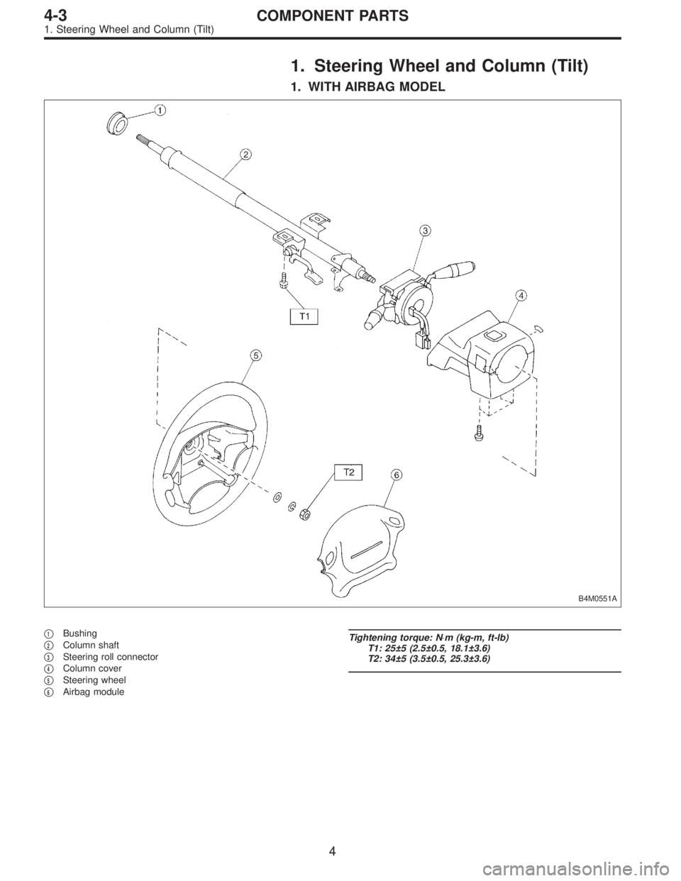
1. Steering Wheel and Column (Tilt)
1. WITH AIRBAG MODEL
B4M0551A
�1Bushing
�
2Column shaft
�
3Steering roll connector
�
4Column cover
�
5Steering wheel
�
6Airbag module
Tightening torque: N⋅m (kg-m, ft-lb)
T1: 25±5 (2.5±0.5, 18.1±3.6)
T2: 34±5 (3.5±0.5, 25.3±3.6)
4
4-3COMPONENT PARTS
1. Steering Wheel and Column (Tilt)
Page 1116 of 2890
1. Supplemental Restraint System
“Airbag”
Airbag system wiring harness is routed near the steering
wheel, steering shaft and column.
WARNING:
�All Airbag system wiring harness and connectors
are colored yellow. Do not use electrical test equip-
ment on these circuit.
�Be careful not to damage Airbag system wiring har-
ness when servicing the steering wheel, steering shaft
and column.
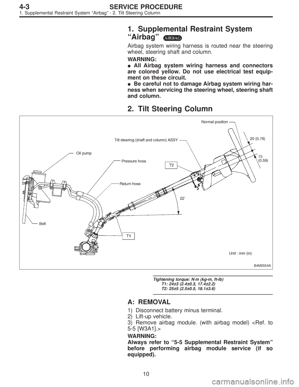
2. Tilt Steering Column
B4M0554A
Tightening torque: N⋅m (kg-m, ft-lb)
T1: 24±3 (2.4±0.3, 17.4±2.2)
T2: 25±5 (2.5±0.5, 18.1±3.6)
A: REMOVAL
1) Disconnect battery minus terminal.
2) Lift-up vehicle.
3) Remove airbag module. (with airbag model)
5-5 [W3A1].>
WARNING:
Always refer to“5-5 Supplemental Restraint System”
before performing airbag module service (if so
equipped).
10
4-3SERVICE PROCEDURE
1. Supplemental Restraint System“Airbag”- 2. Tilt Steering Column
Page 1117 of 2890
1. Supplemental Restraint System
“Airbag”
Airbag system wiring harness is routed near the steering
wheel, steering shaft and column.
WARNING:
�All Airbag system wiring harness and connectors
are colored yellow. Do not use electrical test equip-
ment on these circuit.
�Be careful not to damage Airbag system wiring har-
ness when servicing the steering wheel, steering shaft
and column.
2. Tilt Steering Column
B4M0554A
Tightening torque: N⋅m (kg-m, ft-lb)
T1: 24±3 (2.4±0.3, 17.4±2.2)
T2: 25±5 (2.5±0.5, 18.1±3.6)
A: REMOVAL
1) Disconnect battery minus terminal.
2) Lift-up vehicle.
3) Remove airbag module. (with airbag model)
5-5 [W3A1].>
WARNING:
Always refer to“5-5 Supplemental Restraint System”
before performing airbag module service (if so
equipped).
10
4-3SERVICE PROCEDURE
1. Supplemental Restraint System“Airbag”- 2. Tilt Steering Column