Page 1629 of 2890
B6M0472A
5) Installing end frame
When assembling end frame to yoke, align notched portion
of end frame with lead wire grommet.
B6M0473A
6) Installing yoke
When installing yoke to magnetic switch, align notch of
yoke with protrusion of magnetic switch.
G6M0095
2. Generator
A: REMOVAL AND INSTALLATION
1) Disconnect battery ground cable.
G2M0088
2) Disconnect connector and terminal from generator.
G2M0286
3) Remove V-belt cover.
4) Remove front side V-belt.
15
6-1SERVICE PROCEDURE
1. Starter - 2. Generator
Page 1635 of 2890
2) Check operation as shown in chart below.
No.Switch operation
Value of
voltage meterLamp operation
Remarks
123 12
1 ON OFF OFF 12 V DIM ONCheck initial
excitation.
2 ON ON OFF 12 VON
or
BLINKOFF Check total excitation.
3 ON ON OFF 16 VOFF
or
DIM-BLINKOFFWhen value of voltage
meter is between 12
V and 16 V.
4 OFF ON OFF 12 VON
or
BLINKONCheck connection for
S and B terminals.
5 OFF ON ON 18 V ON ONCheck for over
loading of voltage.
G6M0077
D: ASSEMBLY
Assembly is in the reverse order of disassembly proce-
dures.
CAUTION:
�When disassembling generator, replace rear ball
bearing.
�When soldering starter coil to diode, do not touch
lead wire with solder for more than 5 seconds.
B6M0492
�Before installing rear cover, insert pin from outside
of rear cover so that holds brush. After installing rear
cover, remove pin.
B6M0476A
�When installing rear cover, heat portion�Ato 50°C
(122°F) with heater drier.
21
6-1SERVICE PROCEDURE
2. Generator
Page 1653 of 2890
Magnet switch poor contact or discontinuity
of pull-in coil circuit
Improper sliding of m")
1. Starter
Trouble Probable cause
Starter does not start.Magnet switch does not operate.
(no clicks are heard.)Magnet switch poor contact or discontinuity
of pull-in coil circuit
Improper sliding of magnet switch plunger
Magnet switch operates.
(clicks are issued.)Poor contact of magnet switch’s main con-
tact point
Layer short of armature
Contaminants on armature commutator
High armature mica
Improper grounding of yoke field coil
Insufficient carbon brush length
Insufficient brush spring pressure
Starter starts but does not crank engine.Failure of pinion gear to engage ring gearWorn pinion teeth
Improper sliding of overrunning clutch
Improper adjustment of stud bolt
Clutch slippage Faulty clutch roller spring
Starter starts but engine cranks too slowly.Poor contact of magnet switch’s main con-
tact point
Layer short of armature
Discontinuity, burning or wear of armature
commutator
Poor grounding of yoke field coil
Insufficient brush length
Insufficient brush spring pressure
Abnormal brush wear
Starter overruns.Magnet switch coil is a layer short.
36
6-1DIAGNOSTICS
1. Starter
Page 1716 of 2890

B6M0361A
22. Security System
A: REMOVAL AND INSTALLATION
1. STARTER INTERRUPT RELAY
NOTE:
The starter interrupt relay and headlight alarm relay use the
same parts and are mounted parallel to each other.
Therefore, before removal and installation, identify the
starter interrupt relay by the color of its wiring connection.
1) Remove instrument panel lower cover.
2) Disconnect connector of starter interrupt relay.
3) Remove starter interrupt relay.
4) Installation is in the reverse order of removal.
B6M0361A
2. HEADLIGHT ALARM RELAY
NOTE:
The headlight alarm relay and starter interrupt relay use the
same parts and are mounted parallel to each other.
Therefore, before removal and installation, identify the
headlight alarm relay by the color of its wiring connection.
1) Remove instrument panel lower cover.
2) Disconnect connector of headlight alarm relay.
3) Remove headlight alarm relay.
4) Installation is in the reverse order of removal.
B6M0363A
3. ENGINE HOOD SWITCH
1) Disconnect connector of engine hood switch from bot-
tom side of switch body.
2) Remove headlight (LH).
3) Remove attaching bolt, and then remove engine hood
switch.
4) Installation is in the reverse order of removal.
52
6-2SERVICE PROCEDURE
22. Security System
Page 1720 of 2890
 Disconnect connector of starter interrupt relay.
2) Connect battery to terminal No.1 and ground terminal
No. 2.
3) Check continuity between termina")
B6M0375A
B: INSPECTION
1. STARTER INTERRUPT RELAY
1) Disconnect connector of starter interrupt relay.
2) Connect battery to terminal No.1 and ground terminal
No. 2.
3) Check continuity between terminals as indicated in
table below:
When current flows. Between terminals
No. 3 and No. 5Continuity does not
exist.
When current does not flow. Between terminals
No. 3 and No. 5Continuity exists.
Between terminals
No. 1 and No. 2Continuity exists.
G6M0134
2. HEADLIGHT ALARM RELAY
1) Disconnect connector of headlight alarm relay.
2) Connect battery to terminal No. 1 and ground terminal
No. 2.
3) Check continuity between terminals as indicated in
table below:
When current flows. Between terminals
No. 3 and No. 5Continuity does not
exist.
Between terminals
No. 3 and No. 4Continuity exists.
When current does not flow. Between terminals
No. 3 and No. 5Continuity exists.
Between terminals
No. 3 and No. 4Continuity does not
exist.
Between terminals
No. 1 and No. 2Continuity exists.
B6M0376
3. ENGINE HOOD SWITCH
1) Disconnect connector of engine hood switch.
2) Check continuity between terminals when push rod is
pushed in 1.5 mm (0.059 in) of its stroke.
Terminal
Switch position12
When push rod is
pushed in.
When push rod is
released.��
56
6-2SERVICE PROCEDURE
22. Security System
Page 1727 of 2890
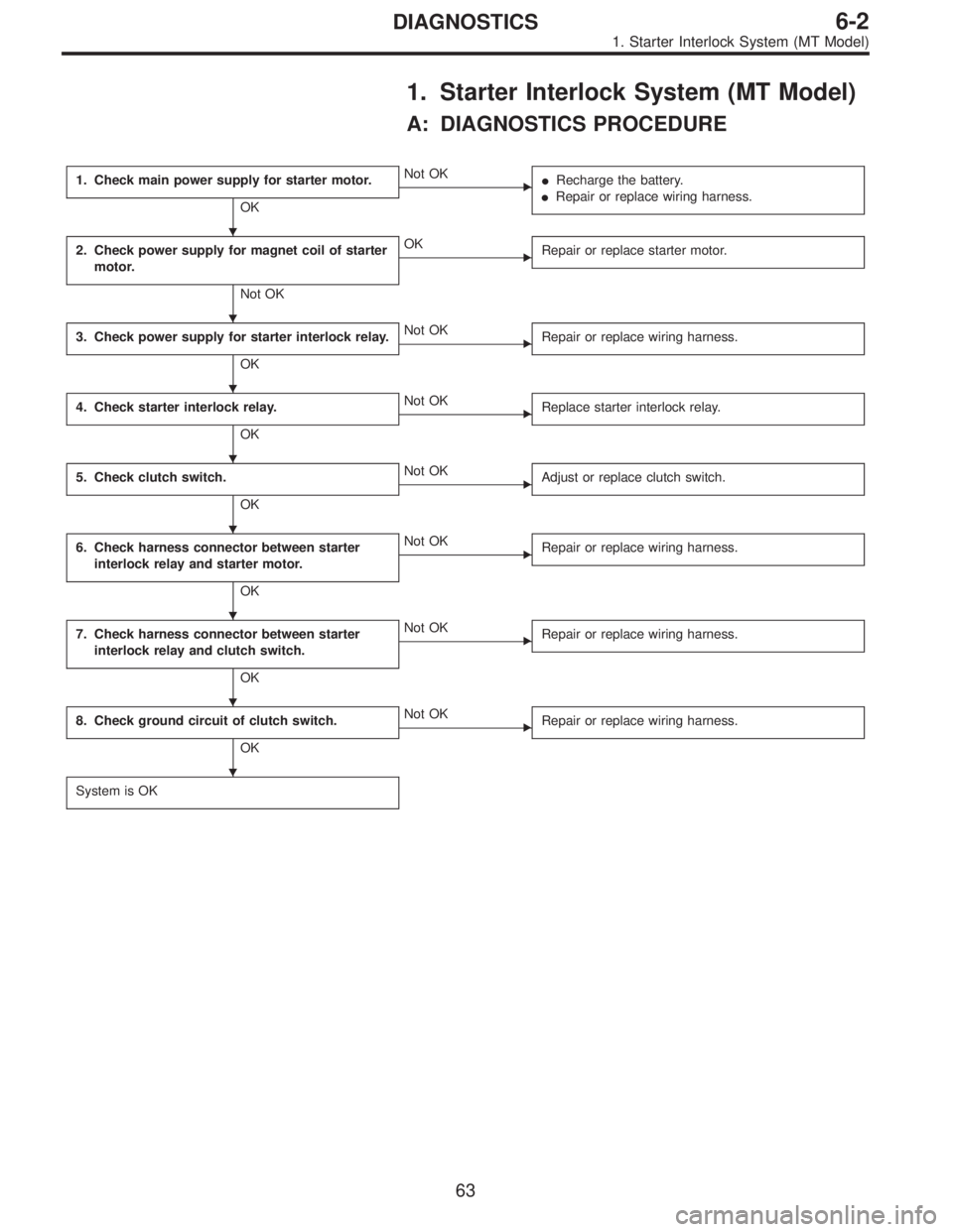
1. Starter Interlock System (MT Model)
A: DIAGNOSTICS PROCEDURE
1. Check main power supply for starter motor.
OK
�Not OK
�Recharge the battery.
�Repair or replace wiring harness.
2. Check power supply for magnet coil of starter
motor.
Not OK
�OK
Repair or replace starter motor.
3. Check power supply for starter interlock relay.
OK
�Not OK
Repair or replace wiring harness.
4. Check starter interlock relay.
OK
�Not OK
Replace starter interlock relay.
5. Check clutch switch.
OK
�Not OK
Adjust or replace clutch switch.
6. Check harness connector between starter
interlock relay and starter motor.
OK
�Not OK
Repair or replace wiring harness.
7. Check harness connector between starter
interlock relay and clutch switch.
OK
�Not OK
Repair or replace wiring harness.
8. Check ground circuit of clutch switch.
OK
�Not OK
Repair or replace wiring harness.
System is OK
�
�
�
�
�
�
�
�
63
6-2DIAGNOSTICS
1. Starter Interlock System (MT Model)
Page 1728 of 2890

B6M0383A
1. CHECK MAIN POWER SUPPLY FOR STARTER
MOTOR.
Measure voltage between starter motor terminal B and
body.
Connector & terminal / Specified voltage:
Terminal B—Body / 10 V, or more
B6M0384A
2. CHECK POWER SUPPLY FOR MAGNET COIL OF
STARTER MOTOR.
1) Disconnect all connectors from starter motor.
2) Turn ignition switch to ST (START).
3) Depress clutch pedal.
4) Measure voltage between starter motor terminal S con-
nector and body.
Connector & terminal / Specified voltage:
(B14) Terminal S—Body / 10 V, or more
B6M0385A
3. CHECK POWER SUPPLY FOR STARTER
INTERLOCK RELAY.
1) Disconnect all connectors from starter motor.
2) Disconnect connector of starter interlock relay.
3) Turn ignition switch to ST (START).
4) Measure voltage between starter interlock relay con-
nector and body.
Connector & terminal / Specified voltage:
(B105) No. 2—Body / 10 V, or more
(B105) No. 4—Body / 10 V, or more
B6M0386A
4. CHECK STARTER INTERLOCK RELAY.
1) Disconnect connector of starter interlock relay.
2) Connect battery to terminal No. 2 and ground terminal
No. 1.
3) Check continuity between terminals as indicated in
table below:
When current flows. Between terminals
No. 3 and No. 4Continuity exists.
When current does not flow. Between terminals
No. 3 and No. 4Continuity does not
exist.
Between terminals
No. 1 and No. 2Continuity exists.
64
6-2DIAGNOSTICS
1. Starter Interlock System (MT Model)
Page 1729 of 2890
 Disconnect connector of clutch switch.
2) Check continuity between terminals when clutch pedal
is depressed/released.
Terminals / Specified resistance:
No. 1—No.2/")
G6M0184
5. CHECK CLUTCH SWITCH.
1) Disconnect connector of clutch switch.
2) Check continuity between terminals when clutch pedal
is depressed/released.
Terminals / Specified resistance:
No. 1—No.2/10Ω, max.
(Without pedal depressing.)
/1MΩ, min. (Pedal depressing.)
B6M0387A
6. CHECK HARNESS CONNECTOR BETWEEN
STARTER INTERLOCK RELAY AND STARTER
MOTOR.
1) Disconnect connectors of starter interlock relay and
starter motor.
2) Measure resistance of harness connector between
starter interlock relay and starter motor.
Connector & terminal / Specified resistance:
(B105) No. 3—(B14) terminalS/10Ω, max.
B6M0388A
7. CHECK HARNESS CONNECTOR BETWEEN
STARTER INTERLOCK RELAY AND CLUTCH SWITCH.
1) Disconnect connectors of starter interlock relay and
clutch switch.
2) Measure resistance of harness connector between
starter interlock relay and clutch switch.
Connector & terminal / Specified resistance:
(B105) No. 1—(B106) No.2/10Ω, max.
B6M0389A
8. CHECK GROUND CIRCUIT OF CLUTCH SWITCH.
1) Disconnect connector of clutch switch.
2) Measure resistance of harness connector between
clutch switch and body.
Connector & terminal / Specified resistance:
(B106) No. 1—Body / 10Ω, max.
65
6-2DIAGNOSTICS
1. Starter Interlock System (MT Model)
 Installing end frame
When assembling end frame to yoke, align notched portion
of end frame with lead wire grommet.
B6M0473A
6) Installing yoke
When installing yoke to magnetic switch, alig")
 Check operation as shown in chart below.
No.Switch operation
Value of
voltage meterLamp operation
Remarks
123 12
1 ON OFF OFF 12 V DIM ONCheck initial
excitation.
2 ON ON OFF 12 VON
or
BLINKOFF Che")