Page 188 of 2890
cal
Wiring
Harness
and
Ground
Point
Connector
Connecting
to
Pole
Color
Area
No
.
Name
2
Brown
B-2
Pressure
sources
switching
solenoid
3
Black
B-2
Pressure
sensor
5
Gray
B-2
Mass
air
flow
sensor
2
Gray
B-2
AT
dropping
resistor
4
Gray
B-3
Cruise
control
pump
6B-3Front
wipermotor
2
Black
A-2
FWD
switch
16
Gray
B-3
T4
T
i
12
Gray
B-2
T3
ransmiss
on
6
Gray
B-3
Ignitor
1
Black
B-3
Starter
(Magnet)
2
Gray
B-2
Brake
fluid
level
switch
2
Black
B-3
Vehicle
speed
sensor
3
Dark
gray
B-2
Front
oxygen
sensor
4
B-2
T5
Rear
oxygen
sensor
cord
(Other
models)
4
B-2
Rear
oxygen
sensor
(California
model)
6Light
gray
B-2
E1
12Light
gray
B-2
E2Engine
wiring
harness
16Light
gray
B-2
E3
2
Back
B-3
3
B-3
MIB
1
Brown
B-3
2B-2
Rear
washer
motor
2f
Green
B-3Front
washer
motor
2
.
BULKHEAD
WIRING
HARNESS
AND
GROUND
POINT
(IN
ENGINE
ROOM)
2
I
a
B
C
-r
t
n
GB-4
GB-5
(
rbag
mode
)
B6M0086B
D
1
3
4
4
[D802]
B6M0587A
A
B
C
D
21
Page 189 of 2890

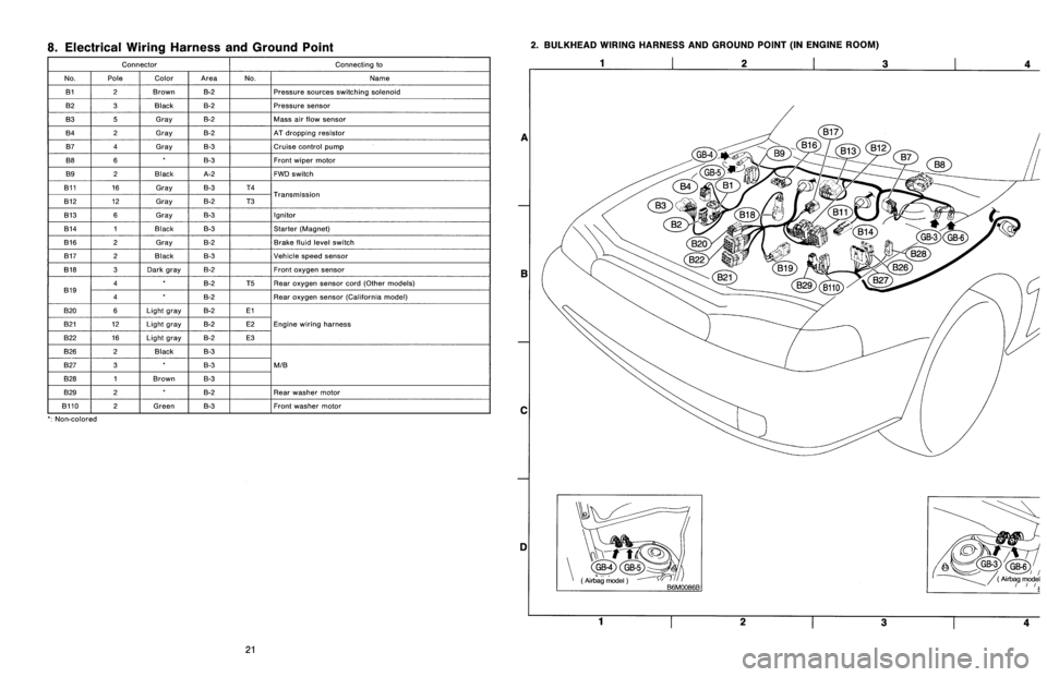
8
.
Electrical
Wiring
Harness
and
Ground
Point
Connector
Connecting
to
No
.
Pole
Color
Area
No
.
Name
131
2
Brown
B-2
Pressure
sources
switching
solenoid
B2
3
Black
B-2
Pressure
sensor
B3
5
Gray
B-2
Mass
air
slow
sensor
B4
2
Gray
B-2
AT
dropping
resistor
B7
4
Gray
B-3
Cruise
control
pump
B8
6B-3Front
wiper
motor
B9
2
Black
A-2
FWD
switch
B11
16
Gray
B-3
T4
T
B12
12
Gray
B-2
T3
ransmission
B13
6
Gray
B-3
Ignitor
B14
1
Black
B-3
Starter
(Magnet)
B16
2
Gray
B-2
Brake
fluid
level
switch
B17
2
Black
B-3
Vehicle
speed
sensor
B18
3
Dark
gray
B-2Front
oxygen
sensor
4B-2
T5Rear
oxygen
sensor
cord(Other
models)
B19
4B-2
Rear
oxygen
sensor
(California
model)
B20
6Light
gray
B-2El
821
12
Light
gray
B-2
E2Engine
wiring
harness
B22
16
Light
gray
B-2
E3
B26
2
Black
B-3
B27
3B-3
MIB
B28
1
Brown
B-3
B29
2B-2
Rear
washer
motor
B110
~
2
f
Green
B-3
~
Front
washer
motor
`
:
Non-colored
2
.
BULKHEAD
WIRING
HARNESS
AND
GROUND
POINT
(IN
ENGINE
ROOM)
1
2
3
a
E
C
DI
Yi-t
~
GB-4GB-5
(Air
`bag
model
(
Airbag
model
~rrE
1
23
4
21
Page 220 of 2890
![SUBARU LEGACY 1996 Service Repair Manual
ON-BOARD
DIAGNOSTICS
11
SYSTEM
[T10A0]
2-7
10
.
Diagnostics
Chart
with
Trouble
Code
DTC
No
.
Abbreviation
(Subaru
select
monitor)Item
Page
P0500
VSP
Vehicle
speed
sensor
malfunction
1
P0505
I SUBARU LEGACY 1996 Service Repair Manual
ON-BOARD
DIAGNOSTICS
11
SYSTEM
[T10A0]
2-7
10
.
Diagnostics
Chart
with
Trouble
Code
DTC
No
.
Abbreviation
(Subaru
select
monitor)Item
Page
P0500
VSP
Vehicle
speed
sensor
malfunction
1
P0505
I](/manual-img/17/57433/w960_57433-219.png)
ON-BOARD
DIAGNOSTICS
11
SYSTEM
[T10A0]
2-7
10
.
Diagnostics
Chart
with
Trouble
Code
DTC
No
.
Abbreviation
(Subaru
select
monitor)Item
Page
P0500
VSP
Vehicle
speed
sensor
malfunction
'1
P0505
ISC
Idle
control
system
malfunction
`1
P0506
ISC
-
L
Idle
control
system
RPM
lower
than
expected
'1
P0507
ISC
-
H
Idle
control
system
RPM
higher
than
expected
'1
P0600
-
Serial
communication
link
malfunction
`1
P0601
RAM
Internal
control
module
memory
check
sum
error
'1
P0703
ATBRK
Brake
switch
input
malfunction
'1
P0705
ATRNG
Transmissionrange
sensor
circuit
malfunction
`1
P0710
ATF
Transmission
fluid
temperature
sensor
circuit
malfunction
'1
P0720
ATVSP
Output
speed
sensor
(vehicle
speed
sensor
1)
circuit
malfunction
'1
P0725
ATNE
Engine
speed
input
circuit
malfunction
'1
P0731
ATGR1
Gear
1
incorrect
ratio
P0732
ATGR2
Gear
2
incorrect
ratio
"
1
P0733
ATGR3
Gear
3
incorrect
ratio
P0734
ATGR4
Gear
4
incorrect
ratio
P0740
ATLU
-
F
Torque
converter
clutch
system
malfunction
1
P0743
ATLU
Torque
converter
clutch
system
electrical
*1
P0748
ATPL
Pressure
control
solenoid
electrical
'1
P0753
ATSFTi
Shift
solenoid
A
electrical
`1
P0758
ATSFT2
Shift
solenoid
B
electrical
'1
P0760
ATOVR
-
F
Shift
solenoid
C
malfunction
'1
P0763
ATOVR
Shift
solenoid
C
electrical
'1
P1100
ST-SW
Starter
switch
circuit
malfunction
'1
P1101
N/P
-
SW
Neutral
position
switch
circuit
malfunction
[MT
vehicles]
'1
P1101
N/P
-
SW
Neutral
position
switch
circuit
malfunction
[AT
vehicles]
1
P1102
BR
Pressure
sources
switching
solenoid
valve
circuit
malfunction
'1
P1103
TRQ
Engine
torque
control
signal
circuit
malfunction
`1
P1400
PCVSOL
Fueltank
pressure
control
solenoid
valve
circuit
malfunction
38
P1401
PCV
-
FFueltank
pressure
control
system
function
problem
44
P1402
FIVL
Fuel
level
sensor
circuit
malfunction
46
P1500
FAN
-
1
Radiator
fan
relay
1
circuit
malfunction
'1
P1502
FAN
-
F
Radiator
fan
function
problem
'1
P1700
ATTH
Throttle
position
sensor
circuit
malfunction
for
automatic
transmission
'1
P1701
ATCRS
Cruise
control
set
signal
circuit
malfunction
for
automatic
transmission
'1
P1702
ATDIAG
Automatic
transmission
diagnosis
inputsignal
circuit
malfunction
'1
P0461'2
EXERR22
Fuel
level
sensor
circuit
range/performance
problem
56
"1
:
<
Ref
.
to
2-7
[T11A0]
.*4
>
'2
:
Only
OBD-II
general
scan
tool
displays
DTC
.
Page 305 of 2890

4. Engine Compression
A: MEASUREMENT
1. 2200 cc MODEL
1) After warming-up the engine, turn ignition switch to
OFF.
2) Make sure that the battery is fully charged.
3) Remove all the spark plugs.
4) Disconnect connectors from fuel injectors.
5) Fully open throttle valve.
6) Check the starter motor for satisfactory performance
and operation.
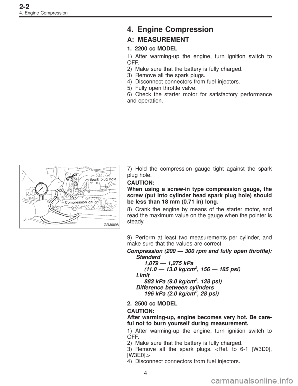
G2M0098
7) Hold the compression gauge tight against the spark
plug hole.
CAUTION:
When using a screw-in type compression gauge, the
screw (put into cylinder head spark plug hole) should
be less than 18 mm (0.71 in) long.
8) Crank the engine by means of the starter motor, and
read the maximum value on the gauge when the pointer is
steady.
9) Perform at least two measurements per cylinder, and
make sure that the values are correct.
Compression (200—300 rpm and fully open throttle):
Standard
1,079—1,275 kPa
(11.0—13.0 kg/cm
2, 156—185 psi)
Limit
883 kPa (9.0 kg/cm
2, 128 psi)
Difference between cylinders
196 kPa (2.0 kg/cm
2, 28 psi)
2. 2500 cc MODEL
CAUTION:
After warming-up, engine becomes very hot. Be care-
ful not to burn yourself during measurement.
1) After warming-up the engine, turn ignition switch to
OFF.
2) Make sure that the battery is fully charged.
3) Remove all the spark plugs.
[W3E0].>
4) Disconnect connectors from fuel injectors.
4
2-2
4. Engine Compression
Page 306 of 2890
5) Fully open throttle valve.
6) Check the starter motor for satisfactory performance
and operation.
B2M0752A
7) Hold the compression gauge tight against the spark
plug hole.
CAUTION:
When using a screw-in type compression gauge, the
screw (put into cylinder head spark plug hole) should
be less than 18 mm (0.71 in) long.
8) Crank the engine by means of the starter motor, and
read the maximum value on the gauge when the pointer is
steady.
9) Perform at least two measurements per cylinder, and
make sure that the values are correct.
Compression (350 rpm and fully open throttle):
Standard
1,216 kPa
(12.4 kg/cm
2, 176 psi)
Limit
941 kPa (9.6 kg/cm
2, 137 psi)
Difference between cylinders
49 kPa (0.5 kg/cm
2, 7 psi), or less
5
2-2
4. Engine Compression
Page 385 of 2890
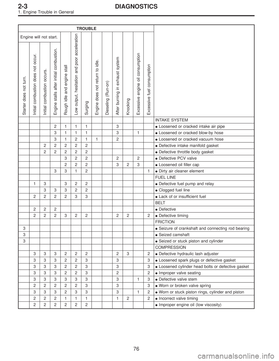
1. Engine Trouble in General
Numbers shown in the chart refer to the possibility of reason for the
trouble in order (“Very often”to“Rarely”)
1—Very often
2—Sometimes
3—Rarely
TROUBLE
Engine will not start.
Rough idle and engine stall
Low output, hesitation and poor acceleration
Surging
Engine does not return to idle.
Dieseling (Run-on)
After burning in exhaust system
Knocking
Excessive engine oil consumption
Excessive fuel consumption Starter does not turn.
Initial combustion does not occur.
Initial combustion occurs.
Engine stalls after initial combustion.
POSSIBLE CAUSE
STARTER
2�Defective battery-to-starter harness
3�Defective starter switch
3�Defective inhibitor switch
23�Defective starter
BATTERY
1�Poor terminal connection
1�Run-down battery
2�Defective charging system
1111111111 1Fuel injection system
Diagnostics II System.>
75
2-3DIAGNOSTICS
1. Engine Trouble in General
Page 386 of 2890

TROUBLE
Engine will not start.
Rough idle and engine stall
Low output, hesitation and poor acceleration
Surging
Engine does not return to idle.
Dieseling (Run-on)
After burning in exhaust system
Knocking
Excessive engine oil consumption
Excessive fuel consumption Starter does not turn.
Initial combustion does not occur.
Initial combustion occurs.
Engine stalls after initial combustion.
INTAKE SYSTEM
2111 3�Loosened or cracked intake air pipe
3111 3 1�Loosened or cracked blow-by hose
31211 2�Loosened or cracked vacuum hose
22222�Defective intake manifold gasket
22222�Defective throttle body gasket
322 2 2�Defective PCV valve
222 323�Loosened oil filler cap
3312 1�Dirty air cleaner element
FUEL LINE
13 322�Defective fuel pump and relay
33322�Clogged fuel line
222233�Lack of or insufficient fuel
BELT
222�Defective
222322 22 2�Defective timing
FRICTION
3�Seizure of crankshaft and connecting rod bearing
3�Seized camshaft
3�Seized or stuck piston and cylinder
COMPRESSION
333222 23 2�Defective hydraulic lash adjuster
333223 3 3�Loosened spark plugs or defective gasket
333223 3 3�Loosened cylinder head bolts or defective gasket
333223 2 2�Improper valve seating
333333 3 13�Defective valve stem
222223 3 3�Worn or broken valve spring
333233 3 12�Worn or stuck piston rings, cylinder and piston
222111 12 2�Incorrect valve timing
222222�Improper engine oil (low viscosity)
76
2-3DIAGNOSTICS
1. Engine Trouble in General
Page 387 of 2890
TROUBLE
Engine will not start.
Rough idle and engine stall
Low output, hesitation and poor acceleration
Surging
Engine does not return to idle.
Dieseling (Run-on)
After burning in exhaust system
Knocking
Excessive engine oil consumption
Excessive fuel consumption Starter does not turn.
Initial combustion does not occur.
Initial combustion occurs.
Engine stalls after initial combustion.
LUBRICATION SYSTEM
22 3 3�Incorrect oil pressure
2�Loosened oil pump attaching bolts and defective
gasket
2�Defective oil filter seal
2�Defective crankshaft oil seal
32�Defective rocker cover gasket
2�Loosened oil drain plug or defective gasket
2�Loosened oil pan fitting bolts or defective oil pan
COOLING SYSTEM
33221�Overheating
333�Over cooling
OTHERS
113 3�Malfunction of Evaporative Emission Control
System
21�Stuck or damaged throttle valve
322 2�Accelerator cable out of adjustment
77
2-3DIAGNOSTICS
1. Engine Trouble in General