Page 756 of 2890
G2M0312
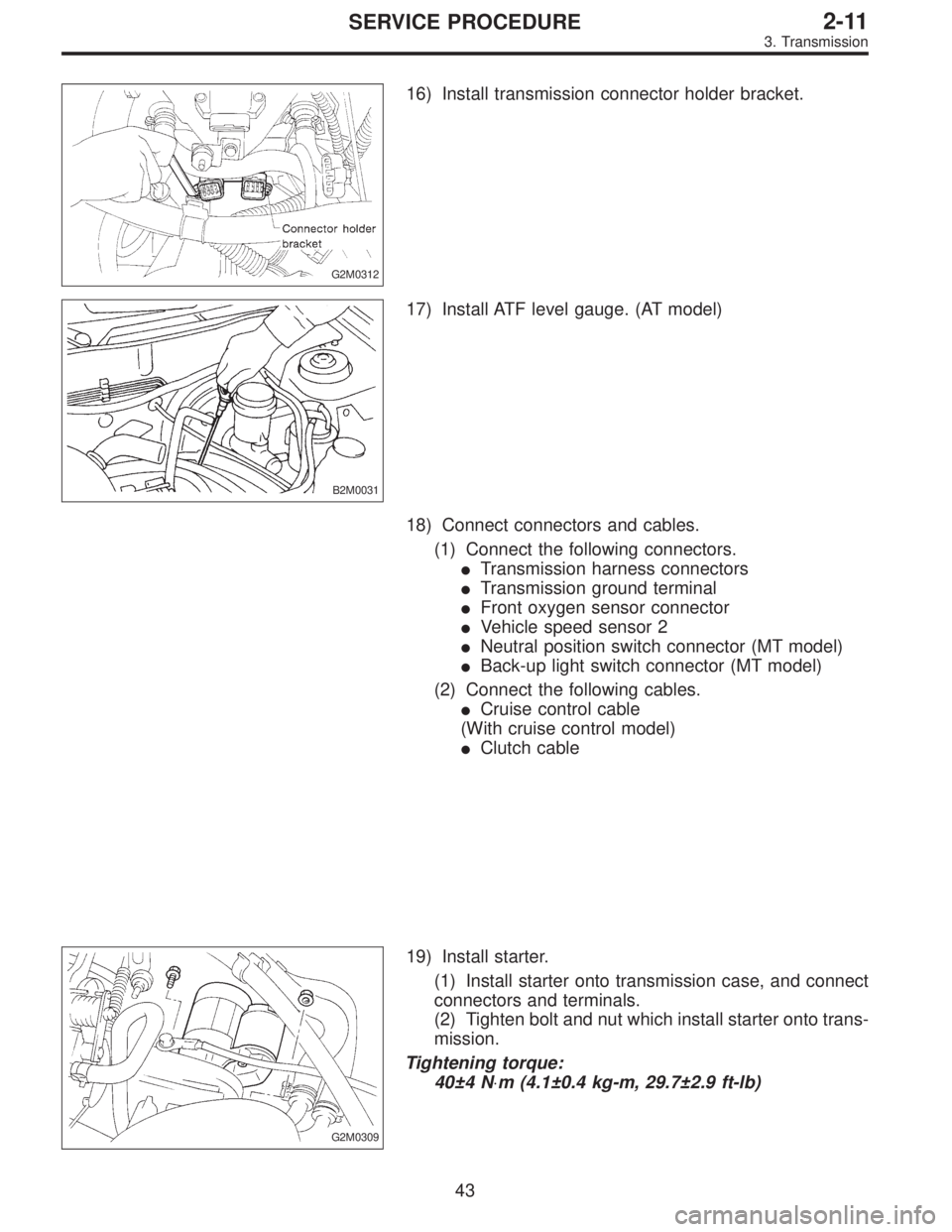
16) Install transmission connector holder bracket.
B2M0031
17) Install ATF level gauge. (AT model)
18) Connect connectors and cables.
(1) Connect the following connectors.
�Transmission harness connectors
�Transmission ground terminal
�Front oxygen sensor connector
�Vehicle speed sensor 2
�Neutral position switch connector (MT model)
�Back-up light switch connector (MT model)
(2) Connect the following cables.
�Cruise control cable
(With cruise control model)
�Clutch cable
G2M0309
19) Install starter.
(1) Install starter onto transmission case, and connect
connectors and terminals.
(2) Tighten bolt and nut which install starter onto trans-
mission.
Tightening torque:
40±4 N⋅m (4.1±0.4 kg-m, 29.7±2.9 ft-lb)
43
2-11SERVICE PROCEDURE
3. Transmission
Page 854 of 2890

G3M0291
2. INHIBITOR SWITCH
The inhibitor switch allows the back-up lights to turn on
when the select lever is in the R range and the starter
motor to start when the lever is in the N or P range. It also
monitors the input signal electronically controlled for each
range and turns on the corresponding range light on the
instrument panel.
When light operation, driving condition or starter motor
operation is erroneous, first check the shift linkage for
improper operation. If the shift linkage is functioning
properly, check the inhibitor switch.
(1) Disconnect cable end from select lever.
(2) Disconnect inhibitor switch connector.
(3) Check continuity in inhibitor switch circuits with
select lever moved to each position.
CAUTION:
Also check that continuity in ignition circuit does not
exist when selector lever is in R, D, 3, 2 and 1 ranges.
PinNo. 432187651211109
Lead color
B Y Br YG W BY R GW BY BW BW RW
Position
P��
��
R����
N����
D��
3��
2��
1��
Signal sent to AT control unit Ignition circuitBack-up light
circuit
B3H0016A
28
3-2SERVICE PROCEDURE
2. On-Car Services
Page 1339 of 2890
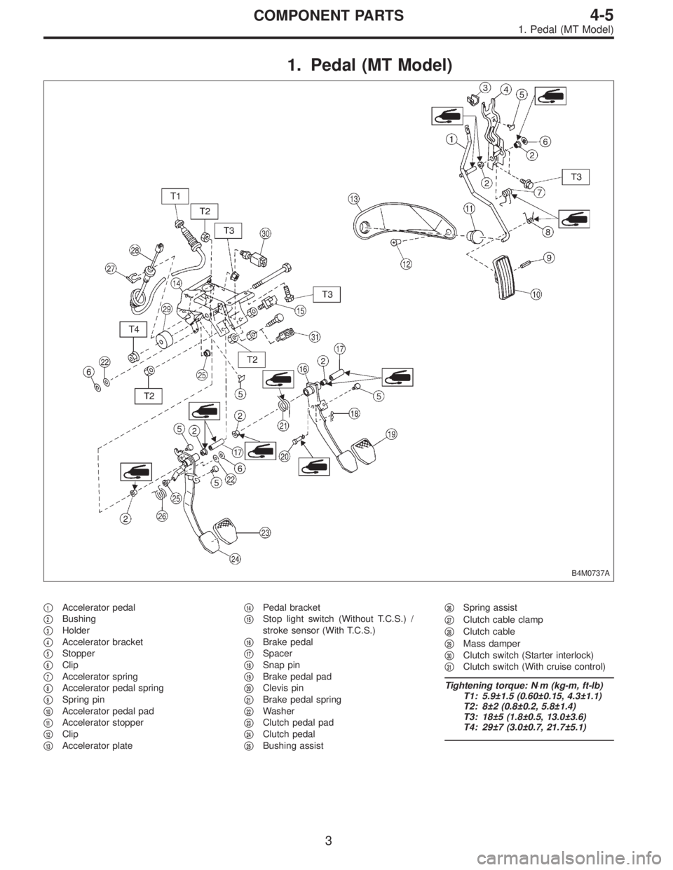
1. Pedal (MT Model)
B4M0737A
�1Accelerator pedal
�
2Bushing
�
3Holder
�
4Accelerator bracket
�
5Stopper
�
6Clip
�
7Accelerator spring
�
8Accelerator pedal spring
�
9Spring pin
�
10Accelerator pedal pad
�
11Accelerator stopper
�
12Clip
�
13Accelerator plate�
14Pedal bracket
�
15Stop light switch (Without T.C.S.) /
stroke sensor (With T.C.S.)
�
16Brake pedal
�
17Spacer
�
18Snap pin
�
19Brake pedal pad
�
20Clevis pin
�
21Brake pedal spring
�
22Washer
�
23Clutch pedal pad
�
24Clutch pedal
�
25Bushing assist�
26Spring assist
�
27Clutch cable clamp
�
28Clutch cable
�
29Mass damper
�
30Clutch switch (Starter interlock)
�
31Clutch switch (With cruise control)
Tightening torque: N⋅m (kg-m, ft-lb)
T1: 5.9±1.5 (0.60±0.15, 4.3±1.1)
T2: 8±2 (0.8±0.2, 5.8±1.4)
T3: 18±5 (1.8±0.5, 13.0±3.6)
T4: 29±7 (3.0±0.7, 21.7±5.1)
3
4-5COMPONENT PARTS
1. Pedal (MT Model)
Page 1615 of 2890

1. Engine Electrical
A: SPECIFICATIONS
Item Designation
StarterType Reduction type
ModelMT
TN128000-8311AT
TN128000-8321
Manufacturer NIPPONDENSO TENNESSEE
Voltage and output 12 V — 1.0 kW 12 V — 1.4 kW
Direction of rotation Counterclockwise (when observed from pinion)
Number of pinion teeth 8 9
No-load
characteristicsVoltage 11 V
Current 90 A or less
Rotating
speed3,000 rpm or more 2,900 rpm or more
Load
characteristicsVoltage 8 V
Current 280 A or less 370 A or less
Torque 9.8 N⋅m (1.0 kg-m, 7.2 ft-lb) 13.7 N⋅m (1.4 kg-m, 10.1 ft-lb)
Rotating
speed900 rpm or more 880 rpm or more
Lock
characteristicsVoltage 5 V
Current 800 A or less 1,050 A or less
Torque 27.5 N⋅m (2.8 kg-m, 20.3 ft-lb) or more
GeneratorType Rotating-field three-phase type, Voltage regulator built-in type
Model LR185-701H
Manufacturer HITACHI AUTOMOTIVE PRODUCTS
Voltage and output 12 V — 85 A
Polarity on ground side Negative
Rotating direction Clockwise (when observed from pulley side)
Armature connection 3-phase Y-type
Output current1,500 rpm — 35 A or more
2,500 rpm — 62 A or more
5,000 rpm — 82 A or more
Regulated voltage 14.5
+0.3
�0.4V [20°C (68°F)]
Ignition
coilModel F-569-01R
Manufacturer Diamond
Primary coil resistance 0.69Ω±10%
Secondary coil resistance 21.0 kΩ±15%
Insulation resistance between
primary terminal and caseMore than 10 MΩ
Spark
plugType and manufacturerRC10YC4 .......... CHAMPION
Alternate
(BKR6E-11 .......... NGK
K20PR-U11 .......... NIPPONDENSO)
Thread size mm 14, P = 1.25
Spark gap mm (in) 1.0 — 1.1 (0.039 — 0.043)
2
6-1SPECIFICATIONS AND SERVICE DATA
1. Engine Electrical
Page 1616 of 2890
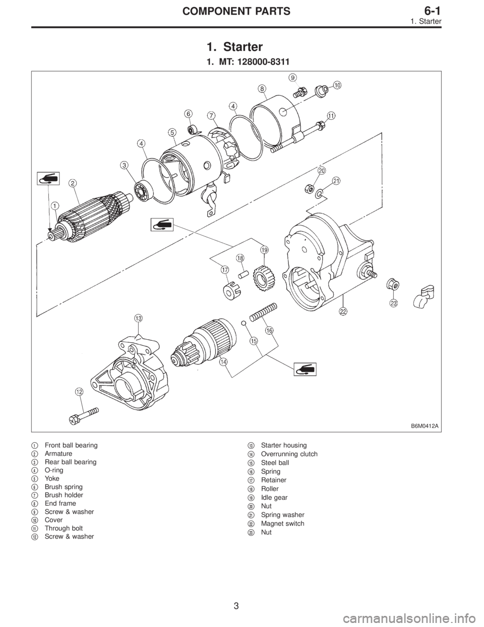
1. Starter
1. MT: 128000-8311
B6M0412A
�1Front ball bearing
�
2Armature
�
3Rear ball bearing
�
4O-ring
�
5Yoke
�
6Brush spring
�
7Brush holder
�
8End frame
�
9Screw & washer
�
10Cover
�
11Through bolt
�
12Screw & washer�
13Starter housing
�
14Overrunning clutch
�
15Steel ball
�
16Spring
�
17Retainer
�
18Roller
�
19Idle gear
�
20Nut
�
21Spring washer
�
22Magnet switch
�
23Nut
3
6-1COMPONENT PARTS
1. Starter
Page 1617 of 2890
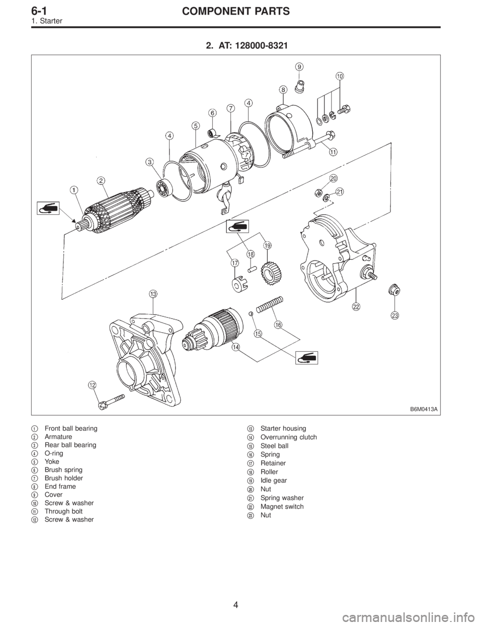
2. AT: 128000-8321
B6M0413A
�1Front ball bearing
�
2Armature
�
3Rear ball bearing
�
4O-ring
�
5Yoke
�
6Brush spring
�
7Brush holder
�
8End frame
�
9Cover
�
10Screw & washer
�
11Through bolt
�
12Screw & washer�
13Starter housing
�
14Overrunning clutch
�
15Steel ball
�
16Spring
�
17Retainer
�
18Roller
�
19Idle gear
�
20Nut
�
21Spring washer
�
22Magnet switch
�
23Nut
4
6-1COMPONENT PARTS
1. Starter
Page 1619 of 2890
G6M0095
1. Starter
A: REMOVAL AND INSTALLATION
1) Disconnect battery ground cable.
G2M0309
2) Disconnect connector and terminal from starter.
3) Remove starter from transmission.
4) Installation is in the reverse order of removal.
Tightening torque:
50±4 N⋅m (5.1±0.4 kg-m, 36.9±2.9 ft-lb)
B: TEST
1. MAGNETIC SWITCH
CAUTION:
�The following magnetic switch tests should be per-
formed with specified voltage applied.
�Each test should be conducted within 3 to 5 sec-
onds. Power to be furnished should be one-half the
rated voltage.
B6M0415A
1) Pull-in test
Connect two battery negative leads onto magnetic switch
body and terminal C respectively. Then connect battery
positive lead onto terminal 50. Pinion should extend when
lead connections are made.
B6M0416A
2) Holding-in test
Disconnect lead from terminal C with pinion extended. Pin-
ion should be held in the extended position.
6
6-1SERVICE PROCEDURE
1. Starter
Page 1620 of 2890
 Return test
Connect two battery negative leads onto terminal 50 and
onto switch body respectively. Then connect battery posi-
tive lead onto terminal C. Next, disconnect lead from ter-
min")
B6M0417A
3) Return test
Connect two battery negative leads onto terminal 50 and
onto switch body respectively. Then connect battery posi-
tive lead onto terminal C. Next, disconnect lead from ter-
minal 50. Pinion should return immediately.
2. PERFORMANCE TEST
The starter is required to produce a large torque and high
rotating speed, but these starter characteristics vary with
the capacity of the battery. It is therefore important to use
a battery with the specified capacity whenever testing the
starter.
The starter should be checked for the following three items:
1. No-load test
Measure the maximum rotating speed and current under a
no-load state.
2. Load test
Measure the magnitude of current needed to generate the
specified torque and rotating speed.
3. Stall test
Measure the torque and current when the armature is
locked.
B6M0418A
1) No-load test
Run single starter under no-load state, and measure its
rotating speed, voltage, and current, using the specified
battery. Measured values must meet the following stan-
dards:
No-load test (Standard):
Voltage/Current
11 V/90 A, or more
Rotating speed
TN128000-8311: 3,000 rpm, or more
TN128000-8321: 3,350 rpm, or more
7
6-1SERVICE PROCEDURE
1. Starter
 Disconnect battery ground cable.
G2M0309
2) Disconnect connector and terminal from starter.
3) Remove starter from transmission.
4) Installation is in")