Page 954 of 2890
G3M0681
6) Connect stay to the bracket.
Tightening torque:
18±5 N⋅m (1.84±0.51 kg-m, 13.3±3.7 ft-lb)
7) Install the exhaust cover.
G3M0698
2. Automatic Transmission
A: REMOVAL
1) Remove the cable.
(1) Prior to removal, set lever to“N”position.
(2) Remove front exhaust pipe.
G3M0699
(3) Separate cable from transmission lever.
(4) Remove clamp from transmission case.
B3M0102A
(5) Disconnect cable from selector lever and then
remove cable bracket.
G3M0702
2) Remove console box.
3) Disconnect the connectors.
11
3-3SERVICE PROCEDURE
1. Manual Transmission - 2. Automatic Transmission
Page 955 of 2890
G3M0681
6) Connect stay to the bracket.
Tightening torque:
18±5 N⋅m (1.84±0.51 kg-m, 13.3±3.7 ft-lb)
7) Install the exhaust cover.
G3M0698
2. Automatic Transmission
A: REMOVAL
1) Remove the cable.
(1) Prior to removal, set lever to“N”position.
(2) Remove front exhaust pipe.
G3M0699
(3) Separate cable from transmission lever.
(4) Remove clamp from transmission case.
B3M0102A
(5) Disconnect cable from selector lever and then
remove cable bracket.
G3M0702
2) Remove console box.
3) Disconnect the connectors.
11
3-3SERVICE PROCEDURE
1. Manual Transmission - 2. Automatic Transmission
Page 956 of 2890
G3M0703
4) Remove the screws to take off the plate from the body.
G3M0704
B: DISASSEMBLY
1) Remove grip from selector lever.
2) Remove indicator from plate.
B3M0346A
3) Remove the following parts from the grip.
�
1Button
�
2Spring
G3M0706
4) Remove shift-lock solenoid and“P”position switch.
G3M0707
5) Remove the bolt to take off the selector lever from the
plate and remove selector lever from the plate.
12
3-3SERVICE PROCEDURE
2. Automatic Transmission
Page 957 of 2890

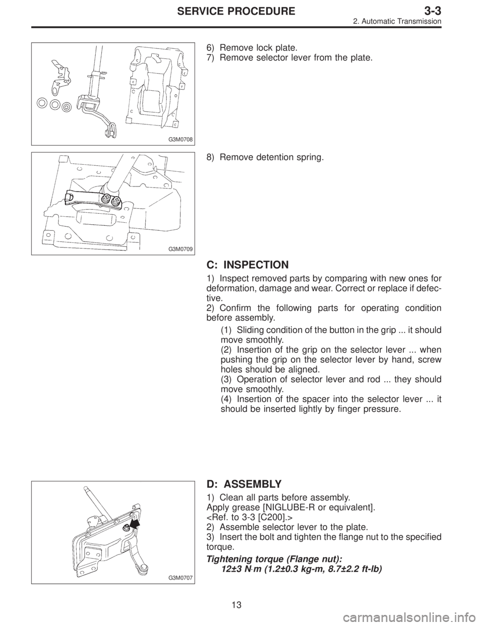
G3M0708
6) Remove lock plate.
7) Remove selector lever from the plate.
G3M0709
8) Remove detention spring.
C: INSPECTION
1) Inspect removed parts by comparing with new ones for
deformation, damage and wear. Correct or replace if defec-
tive.
2) Confirm the following parts for operating condition
before assembly.
(1) Sliding condition of the button in the grip ... it should
move smoothly.
(2) Insertion of the grip on the selector lever ... when
pushing the grip on the selector lever by hand, screw
holes should be aligned.
(3) Operation of selector lever and rod ... they should
move smoothly.
(4) Insertion of the spacer into the selector lever ... it
should be inserted lightly by finger pressure.
G3M0707
D: ASSEMBLY
1) Clean all parts before assembly.
Apply grease [NIGLUBE-R or equivalent].
2) Assemble selector lever to the plate.
3) Insert the bolt and tighten the flange nut to the specified
torque.
Tightening torque (Flange nut):
12±3 N⋅m (1.2±0.3 kg-m, 8.7±2.2 ft-lb)
13
3-3SERVICE PROCEDURE
2. Automatic Transmission
Page 958 of 2890
G3M0710
4) Assemble detention spring, shift-lock solenoid and“P”
position switch.
G3M0711
5) Adjust the position of shift-lock plate and solenoid.
Then, tighten bolts.
G3M0712
6) Assemble indicator to the plate
Tightening torque:
4.4±1.5 N⋅m (0.45±0.15 kg-m, 3.3±1.1 ft-lb)
B3M0347A
7) Assemble the following parts to the grip.
CAUTION:
Apply grease on sliding surfaces of the following
parts.
�
1Button
�
2Spring
G3M0714
8) Assemble the grip to the selector lever.
14
3-3SERVICE PROCEDURE
2. Automatic Transmission
Page 959 of 2890
9) After completion of fitting, transfer selector lever to
range“P”∼“1”, pressing the button of the grip; then check
whether the indicator and select lever agree, whether the
pointer and position mark agree and what the operating
force is.
G3M0703
E: INSTALLATION
1) Mount the selector lever onto the vehicle body.
2) Tighten the six bolts to install the selector lever to the
vehicle body.
Tightening torque:
4.5±1.5 N⋅m (0.45±0.15 kg-m, 3.3±1.1 ft-lb)
G3M0702
3) Connect connectors and install rear console, center
console and instrument console.
G3M0715
4) Set location of selector lever at“N”position.
5) Set location of selector arm installed on the transmis-
sion body at“N”position.
B3M0416A
6) Pass inner cable through selector arm pin and then
connect it using a washer and snap pin.
7) Attach outer cable to plate on transmission case with
the bolts.
Tightening torque:
18±5 N⋅m (1.8±0.5 kg-m, 13.0±3.6 ft-lb)
15
3-3SERVICE PROCEDURE
2. Automatic Transmission
Page 960 of 2890

B3M0417A
8) Insert the thread portion of the other inner cable end
into the connector hole of the selector lever, and fix the
other outer cable end to the bracket.
9) Adjust the inner cable length.
(1) Put connector into contact with nut�
2.
(2) Tighten nut�
1.
Tightening torque:
7.4±2.0 N⋅m (0.75±0.2 kg-m, 5.4±1.4 ft-lb)
10) After completion of fitting, make sure that the selector
lever operates smoothly all across the operating range.
11) Connect the harnesses and check the following items.
(1) The engine starts operating when selector lever is
in position“P”, but not in other positions.
(2) The back-up light is lit when the selector lever is in
position“R”, but not in other positions.
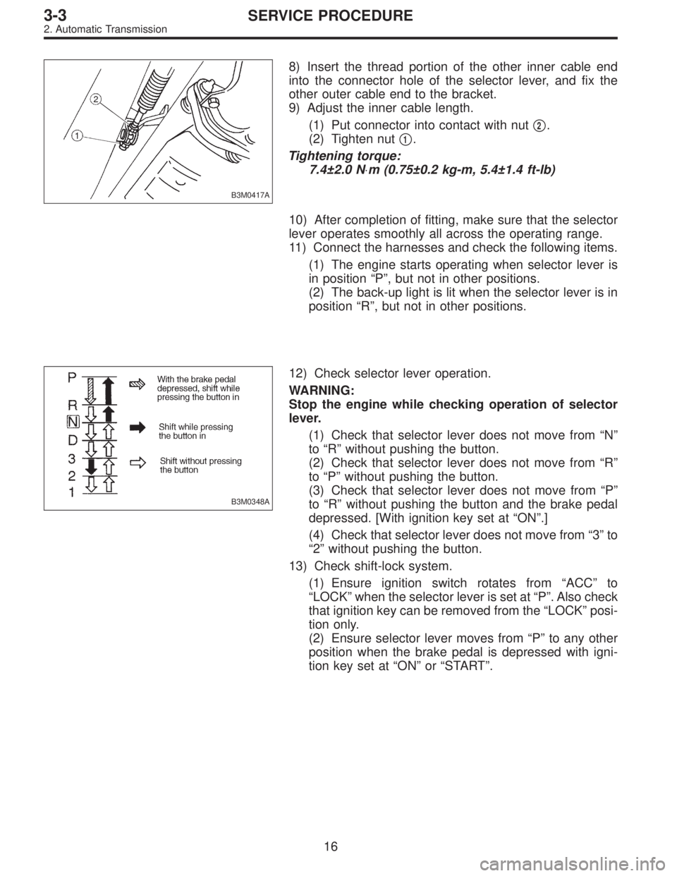
B3M0348A
12) Check selector lever operation.
WARNING:
Stop the engine while checking operation of selector
lever.
(1) Check that selector lever does not move from“N”
to“R”without pushing the button.
(2) Check that selector lever does not move from“R”
to“P”without pushing the button.
(3) Check that selector lever does not move from“P”
to“R”without pushing the button and the brake pedal
depressed. [With ignition key set at“ON”.]
(4) Check that selector lever does not move from“3”to
“2”without pushing the button.
13) Check shift-lock system.
(1) Ensure ignition switch rotates from“ACC”to
“LOCK”when the selector lever is set at“P”. Also check
that ignition key can be removed from the“LOCK”posi-
tion only.
(2) Ensure selector lever moves from“P”to any other
position when the brake pedal is depressed with igni-
tion key set at“ON”or“START”.
16
3-3SERVICE PROCEDURE
2. Automatic Transmission
Page 1203 of 2890

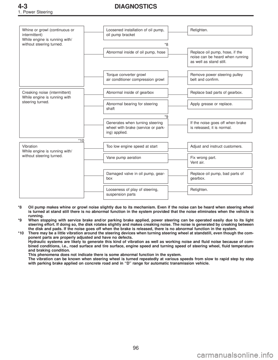
Whine or growl (continuous or
intermittent)
While engine is running with/
without steering turned.Loosened installation of oil pump,
oil pump bracketRetighten.
*8
Abnormal inside of oil pump, hoseReplace oil pump, hose, if the
noise can be heard when running
as well as stand still.
Torque converter growl
air conditioner compression growlRemove power steering pulley
belt and confirm.
Creaking noise (intermittent)
While engine is running with
steering turned.Abnormal inside of gearboxReplace bad parts of gearbox.
Abnormal bearing for steering
shaftApply grease or replace.
*9
Generates when turning steering
wheel with brake (service or park-
ing) applied.If the noise goes off when brake
is released, it is normal.
*10
Vibration
While engine is running with/
without steering turned.
Too low engine speed at startAdjust and instruct customers.
Vane pump aerationFix wrong part.
Vent air.
Damaged valve in oil pump, gear-
boxReplace oil pump, bad parts of
gearbox.
Looseness of play of steering,
suspension partsRetighten.
*8 Oil pump makes whine or growl noise slightly due to its mechanism. Even if the noise can be heard when steering wheel
is turned at stand still there is no abnormal function in the system provided that the noise eliminates when the vehicle is
running.
*9 When stopping with service brake and/or parking brake applied, power steering can be operated easily due to its light
steering effort. If doing so, the disk rotates slightly and makes creaking noise. The noise is generated by creaking between
the disk and pads. If the noise goes off when the brake is released, there is no abnormal function in the system.
*10 There may be a little vibration around the steering devices when turning steering wheel at standstill, even though the com-
ponent parts are properly adjusted and have no defects.
Hydraulic systems are likely to generate this kind of vibration as well as working noise and fluid noise because of com-
bined conditions, i.e., road surface and tire surface, engine speed and turning speed of steering wheel, fluid temperature
and braking condition.
This phenomena does not indicate there is some abnormal function in the system.
The vibration can be known when steering wheel is turned repeatedly at various speeds from slow to rapid step by step
with parking brake applied on concrete road and in“D”range for automatic transmission vehicle.
96
4-3DIAGNOSTICS
1. Power Steering