Page 2071 of 2890
![SUBARU LEGACY 1996 Service Repair Manual 10BB7
CHECK INHIBITOR SWITCH CIRCUIT.
: Is there any trouble in inhibitor switch cir-
cuit?
NOTE:
For the diagnostic procedure on inhibitor switch circuit,
refer to 2-7 [T10AT0].
: Repair or replace i](/manual-img/17/57433/w960_57433-2070.png "SUBARU LEGACY 1996 Service Repair Manual 10BB7
CHECK INHIBITOR SWITCH CIRCUIT.
: Is there any trouble in inhibitor switch cir-
cuit?
NOTE:
For the diagnostic procedure on inhibitor switch circuit,
refer to 2-7 [T10AT0].
: Repair or replace i")
10BB7
CHECK INHIBITOR SWITCH CIRCUIT.
: Is there any trouble in inhibitor switch cir-
cuit?
NOTE:
For the diagnostic procedure on inhibitor switch circuit,
refer to 2-7 [T10AT0].
: Repair or replace inhibitor switch circuit.
: Go to step10BB8.
10BB8
CHECK BRAKE LIGHT SWITCH CIRCUIT.
: Is there any trouble in brake light switch cir-
cuit?
NOTE:
For the diagnostic procedure on brake light switch circuit,
refer to 2-7 [T10AS0].
: Repair or replace brake light switch circuit.
: Go to step10BB9.
10BB9CHECK ATF TEMPERATURE SENSOR
CIRCUIT.
: Is there any trouble in ATF temperature sen-
sor circuit?
NOTE:
For the diagnostic procedure on ATF temperature sensor
circuit, refer to 3-2 [T7F0].
: Repair or replace ATF temperature sensor circuit.
: Go to next.
: Is there poor contact in TCM connector?
: Repair poor contact in TCM connector.
: Go to next.
: Is there any mechanical trouble in automatic
transmission?
: Repair or replace automatic transmission.
: Replace TCM.
303
2-7ON-BOARD DIAGNOSTICS II SYSTEM
10. Diagnostics Chart with Trouble Code
Page 2078 of 2890
 Turn ignition switch to OFF.
2) Connect the Subaru select monitor to data link connec-
tor.
3) Lift-up or raise the vehicle and support with safety
stands.
CAUTI")
OBD0145A
10BG3
CHECK GEAR POSITION.
1) Turn ignition switch to OFF.
2) Connect the Subaru select monitor to data link connec-
tor.
3) Lift-up or raise the vehicle and support with safety
stands.
CAUTION:
On AWD models, raise all wheels off ground.
4) Start and warm-up the engine and transmission.
H2M1150
5) Subaru select monitor switch to ON.
6) Select AT mode using function key.
Press the function key [/], and change to AT mode.
7) Press the function key [0].
G3M0152
8) Designate mode using function key.
Function mode for AT: F10
OBD0615
9) Move selector lever to“D”and drive the vehicle.
10) Read data on Subaru select monitor.
: Does gear position change according to
throttle position and vehicle speed?
: Go to next.
: Go to step10BG4.
: Is there poor contact in TCM connector?
: Repair poor contact in TCM connector.
: Go to next.
: Is there any mechanical trouble in automatic
transmission?
: Repair or replace automatic transmission.
: Replace TCM.
310
2-7ON-BOARD DIAGNOSTICS II SYSTEM
10. Diagnostics Chart with Trouble Code
Page 2079 of 2890
![SUBARU LEGACY 1996 Service Repair Manual 10BG4
CHECK SHIFT SOLENOID 1 CIRCUIT.
: Is there any trouble in shift solenoid 1 cir-
cuit?
NOTE:
For the diagnostic procedure on shift solenoid 1 circuit,
refer to 3-2 [T7E0].
: Repair or replace shi](/manual-img/17/57433/w960_57433-2078.png "SUBARU LEGACY 1996 Service Repair Manual 10BG4
CHECK SHIFT SOLENOID 1 CIRCUIT.
: Is there any trouble in shift solenoid 1 cir-
cuit?
NOTE:
For the diagnostic procedure on shift solenoid 1 circuit,
refer to 3-2 [T7E0].
: Repair or replace shi")
10BG4
CHECK SHIFT SOLENOID 1 CIRCUIT.
: Is there any trouble in shift solenoid 1 cir-
cuit?
NOTE:
For the diagnostic procedure on shift solenoid 1 circuit,
refer to 3-2 [T7E0].
: Repair or replace shift solenoid 1 circuit.
: Go to step10BG5.
10BG5
CHECK SHIFT SOLENOID 2 CIRCUIT.
: Is there any trouble in shift solenoid 2 cir-
cuit?
NOTE:
For the diagnostic procedure on shift solenoid 2 circuit,
refer to 3-2 [T7D0].
: Repair or replace shift solenoid 2 circuit.
: Go to step10BG6.
10BG6
CHECK SHIFT SOLENOID 3 CIRCUIT.
: Is there any trouble in shift solenoid 3 cir-
cuit?
NOTE:
For the diagnostic procedure on shift solenoid 3 circuit,
refer to 3-2 [T7C0].
: Repair or replace shift solenoid 3 circuit.
: Go to next.
: Is there poor contact in TCM connector?
: Repair poor contact in TCM connector.
: Go to next.
: Is there any mechanical trouble in automatic
transmission?
: Repair or replace automatic transmission.
: Replace TCM.
311
2-7ON-BOARD DIAGNOSTICS II SYSTEM
10. Diagnostics Chart with Trouble Code
Page 2129 of 2890
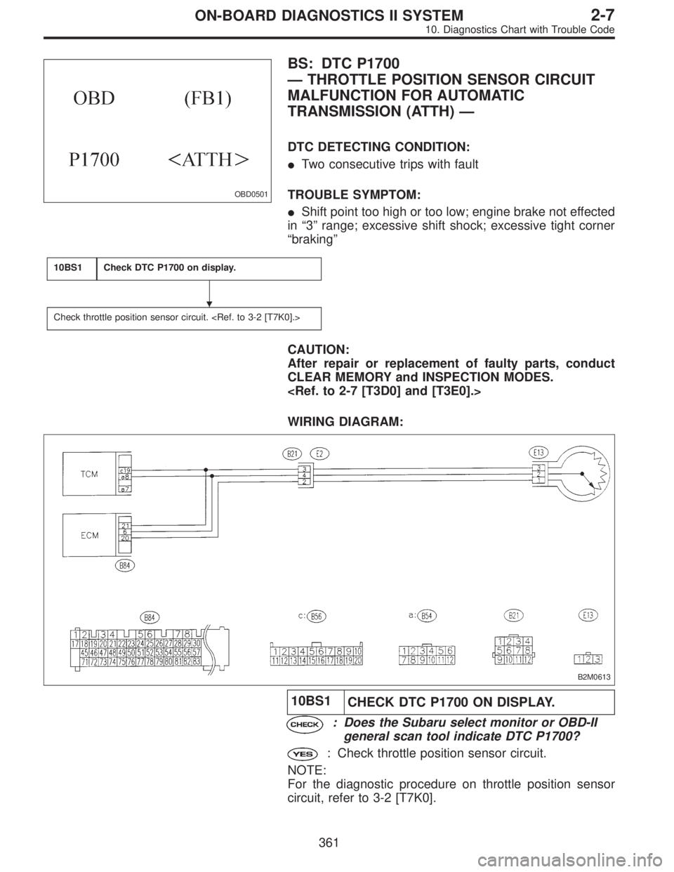
OBD0501
BS: DTC P1700
—THROTTLE POSITION SENSOR CIRCUIT
MALFUNCTION FOR AUTOMATIC
TRANSMISSION (ATTH)—
DTC DETECTING CONDITION:
�Two consecutive trips with fault
TROUBLE SYMPTOM:
�Shift point too high or too low; engine brake not effected
in“3”range; excessive shift shock; excessive tight corner
“braking”
10BS1Check DTC P1700 on display.
Check throttle position sensor circuit.
CAUTION:
After repair or replacement of faulty parts, conduct
CLEAR MEMORY and INSPECTION MODES.
WIRING DIAGRAM:
B2M0613
10BS1
CHECK DTC P1700 ON DISPLAY.
: Does the Subaru select monitor or OBD-II
general scan tool indicate DTC P1700?
: Check throttle position sensor circuit.
NOTE:
For the diagnostic procedure on throttle position sensor
circuit, refer to 3-2 [T7K0].
�
361
2-7ON-BOARD DIAGNOSTICS II SYSTEM
10. Diagnostics Chart with Trouble Code
Page 2130 of 2890
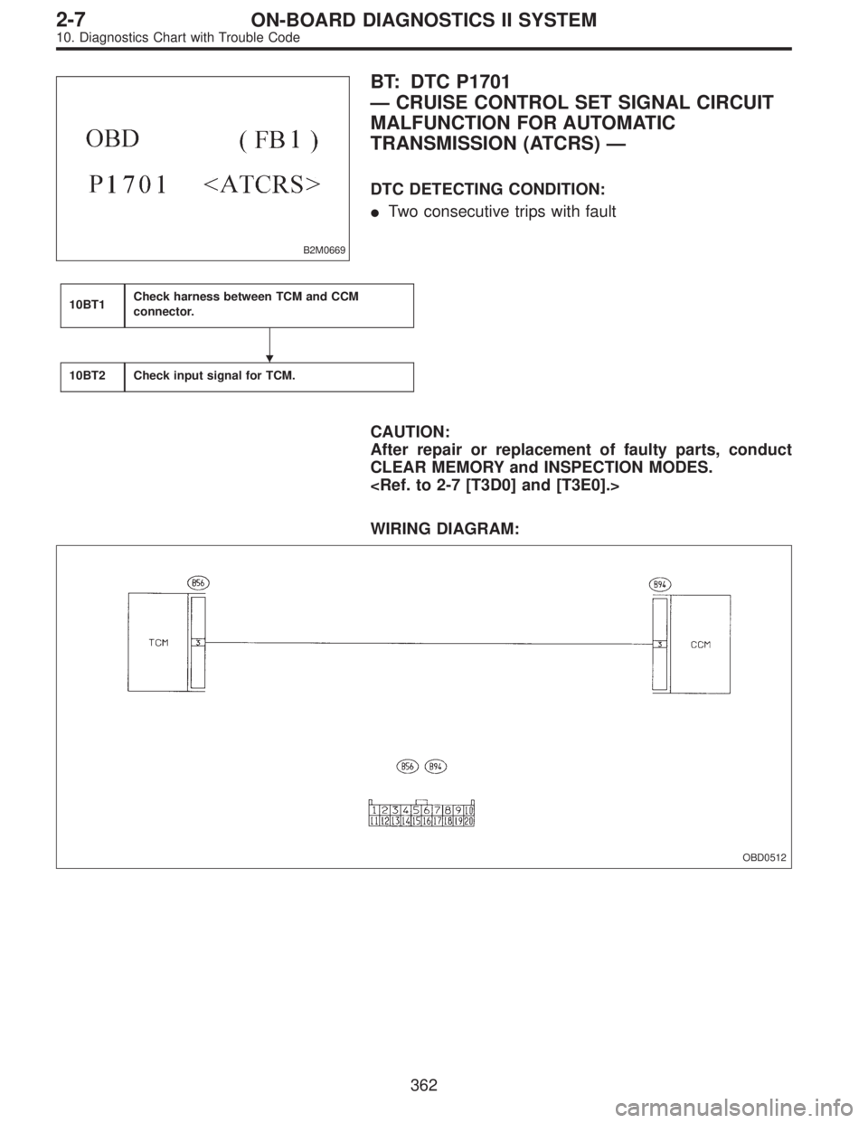
B2M0669
BT: DTC P1701
—CRUISE CONTROL SET SIGNAL CIRCUIT
MALFUNCTION FOR AUTOMATIC
TRANSMISSION (ATCRS)—
DTC DETECTING CONDITION:
�Two consecutive trips with fault
10BT1Check harness between TCM and CCM
connector.
10BT2Check input signal for TCM.
CAUTION:
After repair or replacement of faulty parts, conduct
CLEAR MEMORY and INSPECTION MODES.
WIRING DIAGRAM:
OBD0512
�
362
2-7ON-BOARD DIAGNOSTICS II SYSTEM
10. Diagnostics Chart with Trouble Code
Page 2133 of 2890
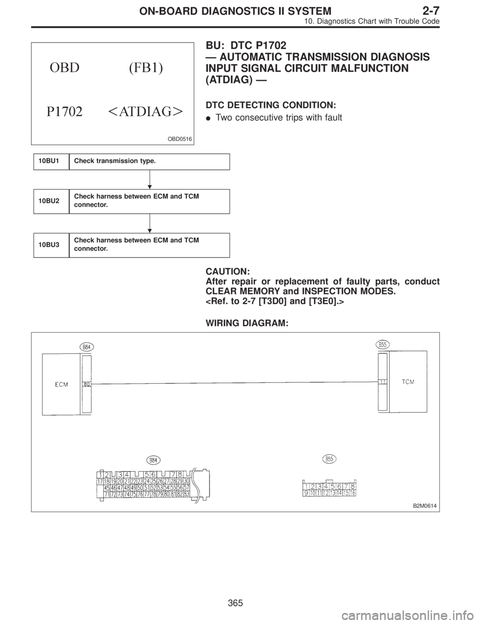
OBD0516
BU: DTC P1702
—AUTOMATIC TRANSMISSION DIAGNOSIS
INPUT SIGNAL CIRCUIT MALFUNCTION
(ATDIAG)—
DTC DETECTING CONDITION:
�Two consecutive trips with fault
10BU1Check transmission type.
10BU2Check harness between ECM and TCM
connector.
10BU3Check harness between ECM and TCM
connector.
CAUTION:
After repair or replacement of faulty parts, conduct
CLEAR MEMORY and INSPECTION MODES.
WIRING DIAGRAM:
B2M0614
�
�
365
2-7ON-BOARD DIAGNOSTICS II SYSTEM
10. Diagnostics Chart with Trouble Code
Page 2140 of 2890
1. Supplemental Restraint System
“Airbag”
Airbag system wiring harness is routed near the transmis-
sion control module (TCM).
�All Airbag system wiring harness and connectors
are colored yellow. Do not use electrical test equip-
ment on these circuit.
�Be careful not to damage Airbag system wiring har-
ness when performing diagnostics and servicing the
TCM.
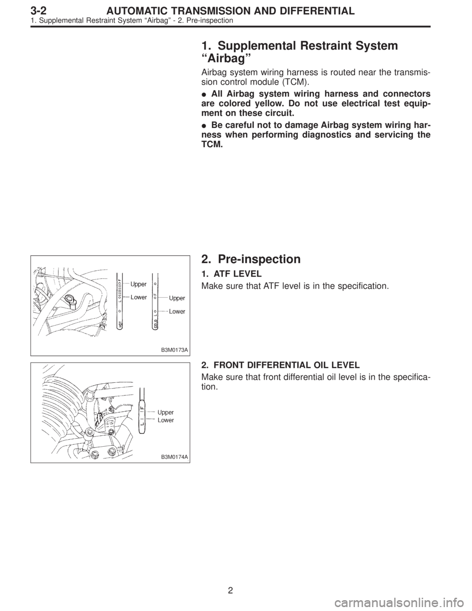
B3M0173A
2. Pre-inspection
1. ATF LEVEL
Make sure that ATF level is in the specification.
B3M0174A
2. FRONT DIFFERENTIAL OIL LEVEL
Make sure that front differential oil level is in the specifica-
tion.
2
3-2AUTOMATIC TRANSMISSION AND DIFFERENTIAL
1. Supplemental Restraint System“Airbag”- 2. Pre-inspection
Page 2141 of 2890
1. Supplemental Restraint System
“Airbag”
Airbag system wiring harness is routed near the transmis-
sion control module (TCM).
�All Airbag system wiring harness and connectors
are colored yellow. Do not use electrical test equip-
ment on these circuit.
�Be careful not to damage Airbag system wiring har-
ness when performing diagnostics and servicing the
TCM.
B3M0173A
2. Pre-inspection
1. ATF LEVEL
Make sure that ATF level is in the specification.
B3M0174A
2. FRONT DIFFERENTIAL OIL LEVEL
Make sure that front differential oil level is in the specifica-
tion.
2
3-2AUTOMATIC TRANSMISSION AND DIFFERENTIAL
1. Supplemental Restraint System“Airbag”- 2. Pre-inspection