Page 848 of 2890
G3M0854
(7) Apply the automatic transmission fluid (ATF) onto
the parts immediately prior to assembly, and the speci-
fied tightening torque should be observed carefully.
(8) Use vaseline if it is necessary to hold parts in the
position when assembling.
(9) Drain ATF and differential gear oil into a saucer so
that the conditions of fluid and oil can be inspected.
(10) Do not support axle drive shaft, stator shaft, input
shaft or various pipes when moving transmission from
one place to another.
(11) Always discard old oil seals and O-ring, and install
new ones.
(12) Do not reuse old aluminum (overrunning clutch
pipes, etc.) pipes, gaskets, spring pins. Install new
ones.
(13) Be sure to replace parts which are damaged,
worn, scratched, discolored, etc.
22
3-2SERVICE PROCEDURE
1. Precaution
Page 849 of 2890
 Raise ATF temperature to 60 to 80°C (140 to 176°F)
from 40 to 60°C (104 to 140°F) (when cold) by driving a
distance of 5 to 10 km (3 to 6 m")
G3M0282
2. On-Car Services
A: INSPECTION
1. ATF LEVEL
1) Raise ATF temperature to 60 to 80°C (140 to 176°F)
from 40 to 60°C (104 to 140°F) (when cold) by driving a
distance of 5 to 10 km (3 to 6 miles).
NOTE:
The level of ATF varies with fluid temperature. Pay atten-
tion to the fluid temperature when checking oil level.
2) Make sure the vehicle is level. After selecting all posi-
tions (P, R, N, D, 3, 2, 1), set the selector leveler in“P”
range. Measure fluid level with the engine idling.
NOTE:
After running, idle the engine for one or two minutes before
measurement.
3) If the fluid level is below the center between upper and
lower marks, add the recommended ATF until the fluid level
is found within the specified range (above the center
between upper and lower marks). When the transmission
is hot, the level should be above the center of upper and
lower marks, and when it is cold, the level should be found
below the center of these two marks.
CAUTION:
�Use care not to exceed the upper limit level.
�ATF level varies with temperature. Remember that
the addition of fluid to the upper limit mark when the
transmission is cold will result in the overfilling of
fluid.
4) Fluid temperature rising speed
�By idling the engine
Time for temperature rise to 60°C (140°F) with atmo-
spheric temperature of 0°C (32°F): More than 25 minutes
Time for temperature rise to 30°C (86°F) with atmo-
spheric temperature of 0°C (32°F): Approx. 8 minutes
�By running the vehicle
Time for temperature rise to 60°C (140°F) with atmo-
spheric temperature of 0°C (32°F): More than 10 minutes
5) Method for checking fluid level upon delivery or at peri-
odic inspection
Check fluid level after a warm-up run of approx. 10 min-
utes. During the warm-up period, the automatic transmis-
sion functions can also be checked.
23
3-2SERVICE PROCEDURE
2. On-Car Services
Page 851 of 2890
G3M0856
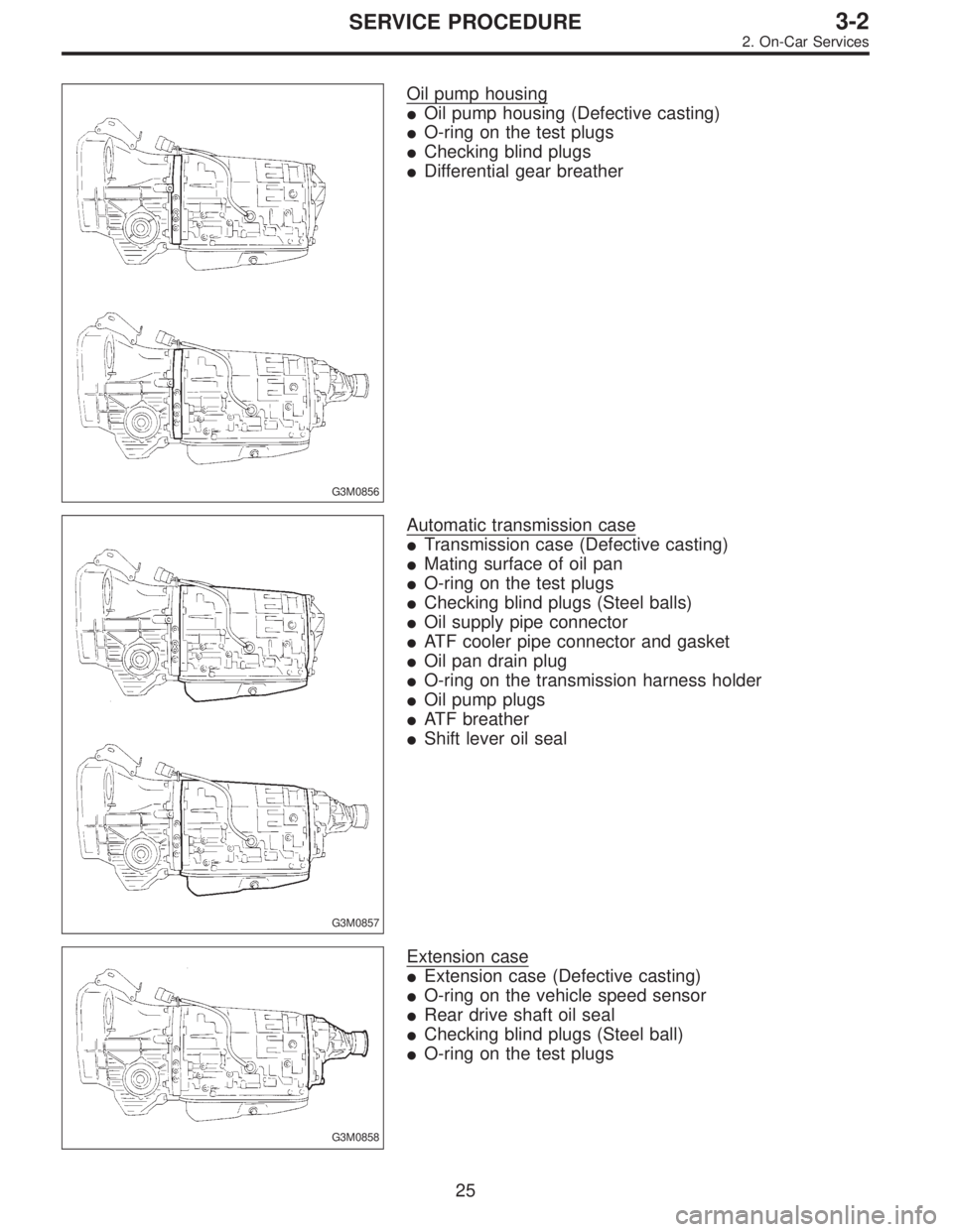
Oil pump housing
�Oil pump housing (Defective casting)
�O-ring on the test plugs
�Checking blind plugs
�Differential gear breather
G3M0857
Automatic transmission case
�Transmission case (Defective casting)
�Mating surface of oil pan
�O-ring on the test plugs
�Checking blind plugs (Steel balls)
�Oil supply pipe connector
�ATF cooler pipe connector and gasket
�Oil pan drain plug
�O-ring on the transmission harness holder
�Oil pump plugs
�ATF breather
�Shift lever oil seal
G3M0858
Extension case
�Extension case (Defective casting)
�O-ring on the vehicle speed sensor
�Rear drive shaft oil seal
�Checking blind plugs (Steel ball)
�O-ring on the test plugs
25
3-2SERVICE PROCEDURE
2. On-Car Services
Page 864 of 2890

3. Performance Test
A: STALL TEST
1. GENERAL
The stall test is of extreme importance in diagnosing the
condition of the automatic transmission and the engine. It
should be conducted to measure the engine stall speeds in
all shift ranges except the P and N ranges.
Purposes of the stall test:
1) To check the operation of the automatic transmission
clutch.
2) To check the operation of the torque converter clutch.
3) To check engine performance.
2. TEST METHODS
Preparations before test:
�
1Check that throttle valve opens fully.
�
2Check that engine oil level is correct.
�
3Check that coolant level is correct.
�
4Check that ATF level is correct.
�
5Check that differential gear oil level is correct.
�
6Increase ATF temperature to 50 to 80°C (122 to 176°F)
by idling the engine for approximately 30 minutes (with
select lever set to“N”or“P”).
1) Install an engine tachometer at a location visible from
the driver’s compartment and mark the stall speed range
on the tachometer scale.
2) Place the wheel chocks at the front and rear of all
wheels and engage the parking brake.
3) Move the manual linkage to ensure it operates properly,
and shift the select lever to the 2 range.
B3M0286B
4) While forcibly depressing the foot brake pedal, gradu-
ally depress the accelerator pedal until the engine operates
at full throttle.
5) When the engine speed is stabilized, read that speed
quickly and release the accelerator pedal.
6) Shift the select lever to Neutral, and cool down the
engine by idling it for more than one minute.
7) Record the stall speed.
8) If stall speed in 2 range is higher than specifications,
forward clutch slipping on brake band slipping may occur.
To identify it, conduct the same test as above in D range.
9) Perform the stall tests with the select lever in the R
range.
CAUTION:
�Do not continue the stall test for MORE THAN FIVE
SECONDS at a time (from closed throttle, fully open
throttle to stall speed reading). Failure to follow this
instruction causes the engine oil and ATF to deterio-
rate and the clutch and brake band to be adversely
affected.
38
3-2SERVICE PROCEDURE
3. Performance Test
Page 869 of 2890

G3M0870
D: TRANSFER CLUTCH PRESSURE TEST
Check transfer clutch pressure in accordance with the fol-
lowing chart in the same manner as with line pressure.
ST 499897700 OIL PRESSURE ADAPTER SET
ST 498575400 OIL PRESSURE GAUGE ASSY
AWD mode:“D”range
FWD mode:“P”range, engine speed 2000 rpm
CAUTION:
Before setting in FWD mode, install spare fuse on FWD
mode switch.
Unit: kPa (kg/cm2, psi)
Duty ratio
(%)AWD mode FWD mode
5667—804
(6.8—8.2, 97—117)667—804
(6.8—8.2, 97—117)
40137—226
(1.4—2.3, 20—33)—
950
(0, 0)—
If oil pressure is not produced or if it does not change in the
AWD mode, the duty solenoid C or transfer valve assem-
bly may be malfunctioning. If oil pressure is produced in the
FWD mode, the problem is similar to that in the AWD
mode.
E: ROAD TEST
1. GENERAL
Road tests should be conducted to properly diagnose the
condition of the automatic transmission.
CAUTION:
When performing test, do not exceed posted speed
limit.
2. CHECKING FOR SHIFT PATTERNS
Check“kick-down”.
D range: 1st
←
→2nd←
→3rd←
→4th
3 range: 1st←
→2nd←
→3rd←4th
2 range: 2nd←3rd←4th
1 range: 1st←2nd←3rd←4th
3. CHECK FOR ENGINE BRAKE OPERATION
Engine brake operation:
D range→4th gear
3 range→3rd gear
2 range→2nd gear
1 range→1st gear
43
3-2SERVICE PROCEDURE
3. Performance Test
Page 874 of 2890
G3M0871
A: DISASSEMBLY
1. EXTERNAL PARTS
1) Place the transmission unit on a work bench, with the
oil pan facing down.
CAUTION:
Be careful not to bend or damage external parts.
G3M0325
2) Remove the drain plug, and drain differential oil. Tighten
the plug temporarily after draining.
G3M0326
3) Remove the drain plug, and drain automatic transmis-
sion fluid (ATF). Tighten the plug temporarily after draining.
G3M0327
4) Extract the torque converter clutch assembly.
NOTE:
�Extract the torque converter clutch horizontally. Be care-
ful not to scratch the bushing inside the oil pump shaft.
�Note that oil pump shaft also comes out.
G3M0328
5) Remove the input shaft.
48
3-2SERVICE PROCEDURE
4. Overall Transmission
Page 947 of 2890
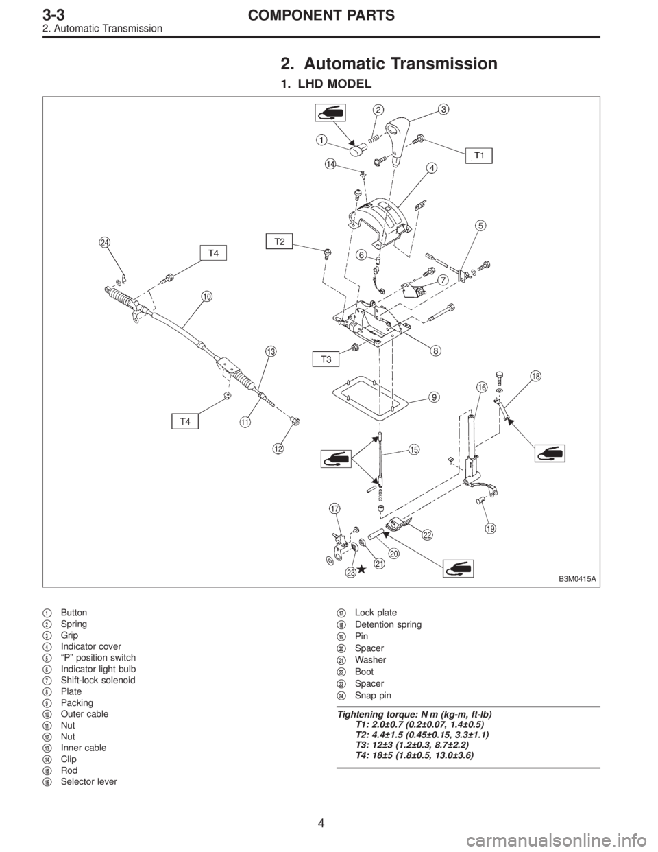
2. Automatic Transmission
1. LHD MODEL
B3M0415A
�1Button
�
2Spring
�
3Grip
�
4Indicator cover
�
5“P” position switch
�
6Indicator light bulb
�
7Shift-lock solenoid
�
8Plate
�
9Packing
�
10Outer cable
�
11Nut
�
12Nut
�
13Inner cable
�
14Clip
�
15Rod
�
16Selector lever�
17Lock plate
�
18Detention spring
�
19Pin
�
20Spacer
�
21Washer
�
22Boot
�
23Spacer
�
24Snap pin
Tightening torque: N⋅m (kg-m, ft-lb)
T1: 2.0±0.7 (0.2±0.07, 1.4±0.5)
T2: 4.4±1.5 (0.45±0.15, 3.3±1.1)
T3: 12±3 (1.2±0.3, 8.7±2.2)
T4: 18±5 (1.8±0.5, 13.0±3.6)
4
3-3COMPONENT PARTS
2. Automatic Transmission
Page 948 of 2890
2. RHD MODEL
B3M0385A
�1Grip
�
2Spring
�
3Button
�
4Indicator cover
�
5“P”position switch
�
6Indicator light bulb
�
7Shift-lock solenoid
�
8Plate
�
9Packing
�
10Outer cable
�
11Nut
�
12Nut
�
13Inner cable
�
14Clip
�
15Rod�
16Selector lever
�
17Lock plate
�
18Detention spring
�
19Pin
�
20Spacer
�
21Washer
�
22Boot
�
23Spacer
�
24Snap pin
Tightening torque: N⋅m (kg-m, ft-lb)
T1: 4.4±1.5 (0.45±0.15, 3.3±1.1)
T2: 12±3 (1.2±0.3, 8.7±2.2)
T3: 18±5 (1.8±0.5, 13.0±3.6)
5
3-3COMPONENT PARTS
2. Automatic Transmission
 Apply the automatic transmission fluid (ATF) onto
the parts immediately prior to assembly, and the speci-
fied tightening torque should be observed carefully.
(8) Use vaseline if it is nec")
 Place the transmission unit on a work bench, with the
oil pan facing down.
CAUTION:
Be careful not to bend or damage external parts.
G3M0325
2) Remove the d")