Page 1206 of 2890

9. BREAKAGE OF HOSES
Pressure hose burstExcessive holding time of relief
statusInstruct customers.
Malfunction of relief valveReplace oil pump.
Poor cold characteristic of fluidReplace fluid.
Forced out return hosePoor connectionCorrect.
Poor holding of clipRetighten.
Poor cold characteristic of fluidReplace fluid.
Fluid bleeding out of hose slightlyWrong layout, tensionedReplace hose.
Excessive play of engine due to
deterioration of engine mounting
rubberReplace defective parts.
Improper stop position of pitching
stopperReplace defective parts.
*11
Crack on hose
Excessive holding time of relief
statusReplace.
Instruct customer.
Excessive tightening torque for
return hose clipReplace.
Power steering fluid, brake fluid,
engine oil, electrolyte adhere on
the hose surfaceReplace.
Pay attention on service work.
Too many times use in extremely
cold weatherReplace.
Instruct customers.
*11 Although surface layer materials of rubber hoses have excellent weathering resistance, heat resistance and resistance for
low temperature brittleness, they are likely to be damaged chemically by brake fluid, battery electrolyte, engine oil and
automatic transmission fluid and their service lives are to be very shortened. It is very important to keep the hoses free
from before mentioned fluids and to wipe out immediately when the hoses are adhered with the fluids.
Since resistances for heat or low temperature brittleness are gradually declining according to time accumulation of hot or
cold conditions for the hoses and their service lives are shortening accordingly, it is necessary to perform careful inspec-
tion frequently when the vehicle is used in hot weather areas, cold weather area and/or a driving condition in which many
steering operations are required in short time. Particularly continuous work of relief valve over 5 seconds causes to reduce
service lives of the hoses, the oil pump, the fluid, etc. due to over heat.
So, avoid to keep this kind of condition when servicing as well as driving.
99
4-3DIAGNOSTICS
1. Power Steering
Page 1210 of 2890
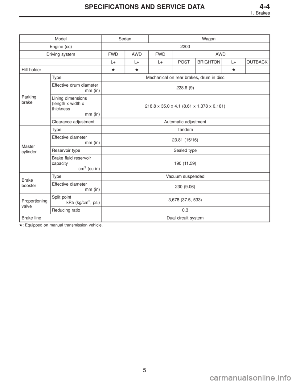
Model Sedan Wagon
Engine (cc) 2200
Driving system FWD AWD FWD AWD
L+ L+ L+ POST BRIGHTON L+ OUTBACK
Hill holder��—— —�—
Parking
brakeType Mechanical on rear brakes, drum in disc
Effective drum diameter
mm (in)228.6 (9)
Lining dimensions
(length x width x
thickness
mm (in)218.8 x 35.0 x 4.1 (8.61 x 1.378 x 0.161)
Clearance adjustment Automatic adjustment
Master
cylinderType Tandem
Effective diameter
mm (in)23.81 (15/16)
Reservoir type Sealed type
Brake fluid reservoir
capacity
cm
3(cu in)190 (11.59)
Brake
boosterType Vacuum suspended
Effective diameter
mm (in)230 (9.06)
Proportioning
valveSplit point
kPa (kg/cm
2, psi)3,678 (37.5, 533)
Reducing ratio 0.3
Brake line Dual circuit system
�: Equipped on manual transmission vehicle.
5
4-4SPECIFICATIONS AND SERVICE DATA
1. Brakes
Page 1780 of 2890
B: AUTOMATIC TRANSMISSION
1. ELECTRONIC-HYDRAULIC CONTROL SYSTEM
The electronic-hydraulic control system consists of various
sensors and switches, a transmission control module
(TCM) and the hydraulic controller including solenoid
valves. The system controls the transmission proper
including shift control, lock-up control, overrunning clutch
control, line pressure control and shift timing control. It also
controls the AWD transfer clutch. In other words, the sys-
tem detects various operating conditions from various input
signals and sends output signals to shift solenoids 1, 2 and
3 and duty solenoids A, B and C (a total of six solenoids).
12
2-7ON-BOARD DIAGNOSTICS II SYSTEM
1. General
Page 1836 of 2890
 Use engine grounding terminal or engine proper as the
grounding point to the body when measuring voltage and
resistance in the engine compartment.
8) Every MFI-related part is a precision")
B2M0648A
7) Use engine grounding terminal or engine proper as the
grounding point to the body when measuring voltage and
resistance in the engine compartment.
8) Every MFI-related part is a precision part. Do not drop
them.
9) Observe the following cautions when installing a radio
in MFI equipped models.
CAUTION:
�The antenna must be kept as far apart as possible
from the control unit.
(The ECM is located under the steering column, inside
of the instrument panel lower trim panel.)
�The antenna feeder must be placed as far apart as
possible from the ECM and MFI harness.
�Carefully adjust the antenna for correct matching.
�When mounting a large power type radio, pay spe-
cial attention to the three items above mentioned.
�Incorrect installation of the radio may affect the
operation of the ECM.
10) Before disconnecting the fuel hose, disconnect the
fuel pump connector and crank the engine for more than
five seconds to release pressure in the fuel system. If
engine starts during this operation, run it until it stops.
11) Problems in the electronic-controlled automatic trans-
mission may be caused by failure of the engine, the elec-
tronic control system, the transmission proper, or by a com-
bination of these. These three causes must be distin-
guished clearly when performing diagnostics.
12) Diagnostics should be conducted by rotating with
simple, easy operations and proceeding to complicated,
difficult operations. The most important thing in diagnostics
is to understand the customer’s complaint, and distinguish
between the three causes.
13) In AT vehicles, do not continue the stall for more than
five seconds at a time (from closed throttle, fully open
throttle to stall engine speed).
14) On ABS or ABS/TCS vehicle, when performing driving
test in jacked-up or lifted-up position, sometimes the warn-
ing light may be lit, but this is not a malfunction of the sys-
tem. The reason for this is the speed difference between
the front and rear wheels. After diagnosis of engine control
system, perform the ABS or ABS/TCS memory clearance
procedure of self-diagnosis system.
[T9K0], 4-4c [T6D2] or [T9J0].>
68
2-7ON-BOARD DIAGNOSTICS II SYSTEM
4. Cautions
Page 1843 of 2890
![SUBARU LEGACY 1996 Service Repair Manual 6. Basic Diagnostics Procedure
Trouble occurs.
Ask the customer when and how the
trouble occurred using interview
check list. <Ref. to 2-7 [T602].>
Start the engine.
Ye s�NoInspection using“8. Diagn](/manual-img/17/57433/w960_57433-1842.png "SUBARU LEGACY 1996 Service Repair Manual 6. Basic Diagnostics Procedure
Trouble occurs.
Ask the customer when and how the
trouble occurred using interview
check list. <Ref. to 2-7 [T602].>
Start the engine.
Ye s�NoInspection using“8. Diagn")
6. Basic Diagnostics Procedure
Trouble occurs.
Ask the customer when and how the
trouble occurred using interview
check list.
Start the engine.
Ye s�NoInspection using“8. Diagnostics for
Engine Start Failure 2-7 [T800]”.
Malfunction indicator lamp (MIL) illu-
minates.
Ye s�NoInspection using“9. General Diag-
nostics Table 2-7 [T900]”.
Inspection using Subaru select moni-
tor or OBD-II general scan tool.
(Subaru select monitor: MODE FB1)
Trouble code
�No trouble code designated.Repair.
See NOTE: *1
designated.
Inspection using“10. Diagnostics
Chart with Trouble Code 2-7
[T1000]”.
See NOTE: *2.
�Trouble code
designated.
�
Repair.
Inspection mode
Inspection using Subaru select moni-
tor or OBD-II general scan tool.
(Subaru select monitor: MODE FB0)
No trouble code
�Clear memory mode.�
designated.
END
NOTE:
*1: If trouble code is not shown on display although the
MIL illuminates, perform diagnostics of the MIL (CHECK
ENGINE LIGHT) circuit or combination meter.
Diagnostics for CHECK ENGINE Malfunction Indicator
Lamp (MIL) 2-7 [T700].”>
*2: Carry out the basic check, only when trouble code
about automatic transmission is shown on display.
2-7 [T601].>
�
�
�
�
�
�
75
2-7ON-BOARD DIAGNOSTICS II SYSTEM
6. Basic Diagnostics Procedure
Page 1844 of 2890
1. BASIC CHECK ITEMS FOR AT
When trouble code about automatic transmission is shown
on display, carry out the following basic check. After that,
carry out the replacement or repair work.
1) ATF level check
2) Differential gear oil level check
3) ATF leak check
4) Differential gear oil leak check
5) Brake band adjustment
6) Stall test
7) Line pressure test
8) Transfer clutch pressure test
9) Time lag test
10) Road test
11) Shift characteristics
NOTE:
As for the method, refer to 3-2 [W2A0], [W2B1], [W300].
76
2-7ON-BOARD DIAGNOSTICS II SYSTEM
6. Basic Diagnostics Procedure
Page 1892 of 2890
Item Page
P0500 VSP Vehicle speed sensor malfunction 266
P0505 ISC Idle control system malfunction 269
P0506 ISC
—L Idle control system RPM lower than expe")
DTC
No.Abbreviation
(Subaru select monitor)Item Page
P0500 VSP Vehicle speed sensor malfunction 266
P0505 ISC Idle control system malfunction 269
P0506 ISC
—L Idle control system RPM lower than expected 276
P0507 ISC
—H Idle control system RPM higher than expected 277
P0600—Serial communication link malfunction 278
P0601 RAM Internal control module memory check sum error 281
P0703 ATBRK Brake switch input malfunction 283
P0705 ATRNG Transmission range sensor circuit malfunction 286
P0710 ATF Transmission fluid temperature sensor circuit malfunction 293
P0720 ATVSP Output speed sensor (vehicle speed sensor 1) circuit malfunction 294
P0725 ATNE Engine speed input circuit malfunction 295
P0731 ATGR1 Gear 1 incorrect ratio
296 P0732 ATGR2 Gear 2 incorrect ratio
P0733 ATGR3 Gear 3 incorrect ratio
P0734 ATGR4 Gear 4 incorrect ratio
P0740 ATLU
—F Torque converter clutch system malfunction 300
P0743 ATLU Torque converter clutch system electrical 304
P0748 ATPL Pressure control solenoid electrical 305
P0753 ATSFT1 Shift solenoid A electrical 306
P0758 ATSFT2 Shift solenoid B electrical 307
P0760 ATOVR
—F Shift solenoid C malfunction 308
P0763 ATOVR Shift solenoid C electrical 312
P1100 ST
—SW Starter switch circuit malfunction 313
P1101 N/P
—SW Neutral position switch circuit malfunction [MT vehicles] 315
P1101 N/P
—SW Neutral position switch circuit malfunction [AT vehicles] 318
P1102 BR Pressure sources switching solenoid valve circuit malfunction 322
P1103 TRQ Engine torque control signal circuit malfunction 328
P1400 PCVSOL Fuel tank pressure control solenoid valve circuit malfunction 331
P1401 PCV
—F Fuel tank pressure control system function problem 337
P1402 FLVL Fuel level sensor circuit malfunction 339
P1500 FAN
—1 Radiator fan relay 1 circuit malfunction 351
P1502 FAN
—F Radiator fan function problem 358
P1700 ATTH Throttle position sensor circuit malfunction for automatic transmission 361
P1701 ATCRS Cruise control set signal circuit malfunction for automatic transmission 362
P1702 ATDIAG Automatic transmission diagnosis input signal circuit malfunction 365
P0461*1 EXERR22 Fuel level sensor circuit range/performance problem 368
*1: Only OBD-II general scan tool displays DTC.
124
2-7ON-BOARD DIAGNOSTICS II SYSTEM
10. Diagnostics Chart with Trouble Code
Page 2067 of 2890
![SUBARU LEGACY 1996 Service Repair Manual 10BA2CHECK THROTTLE POSITION SENSOR
CIRCUIT.
: Is there any trouble in throttle position sen-
sor circuit?
NOTE:
For the diagnostic procedure on throttle position sensor
circuit, refer to 3-2 [T7K0].](/manual-img/17/57433/w960_57433-2066.png "SUBARU LEGACY 1996 Service Repair Manual 10BA2CHECK THROTTLE POSITION SENSOR
CIRCUIT.
: Is there any trouble in throttle position sen-
sor circuit?
NOTE:
For the diagnostic procedure on throttle position sensor
circuit, refer to 3-2 [T7K0].")
10BA2CHECK THROTTLE POSITION SENSOR
CIRCUIT.
: Is there any trouble in throttle position sen-
sor circuit?
NOTE:
For the diagnostic procedure on throttle position sensor
circuit, refer to 3-2 [T7K0].
: Repair or replace throttle position sensor circuit.
: Go to step10BA3.
10BA3CHECK VEHICLE SPEED SENSOR 1 CIR-
CUIT.
: Is there any trouble in vehicle speed sensor
1 circuit?
NOTE:
For the diagnostic procedure on vehicle speed sensor 1
circuit, refer to 3-2 [T7L0].
: Repair or replace vehicle speed sensor 1 circuit.
: Go to step10BA4.
10BA4CHECK VEHICLE SPEED SENSOR 2 CIR-
CUIT.
: Is there any trouble in vehicle speed sensor
2 circuit?
NOTE:
For the diagnostic procedure on vehicle speed sensor 2
circuit, refer to 3-2 [T7M0].
: Repair or replace vehicle speed sensor 2 circuit.
: Go to step10BA5.
10BA5
CHECK ENGINE SPEED INPUT CIRCUIT.
: Is there any trouble in engine speed input
circuit?
NOTE:
For the diagnostic procedure on engine speed input signal
circuit, refer to 3-2 [T7H0].
: Repair or replace engine speed input circuit.
: Go to next.
: Is there poor contact in TCM connector?
: Repair poor contact in TCM connector.
: Go to next.
: Is there any mechanical trouble in automatic
transmission?
: Repair or replace automatic transmission.
: Replace TCM.
299
2-7ON-BOARD DIAGNOSTICS II SYSTEM
10. Diagnostics Chart with Trouble Code
 and the hydraulic")
 ATF level")