Page 2140 of 2890
1. Supplemental Restraint System
“Airbag”
Airbag system wiring harness is routed near the transmis-
sion control module (TCM).
�All Airbag system wiring harness and connectors
are colored yellow. Do not use electrical test equip-
ment on these circuit.
�Be careful not to damage Airbag system wiring har-
ness when performing diagnostics and servicing the
TCM.
B3M0173A
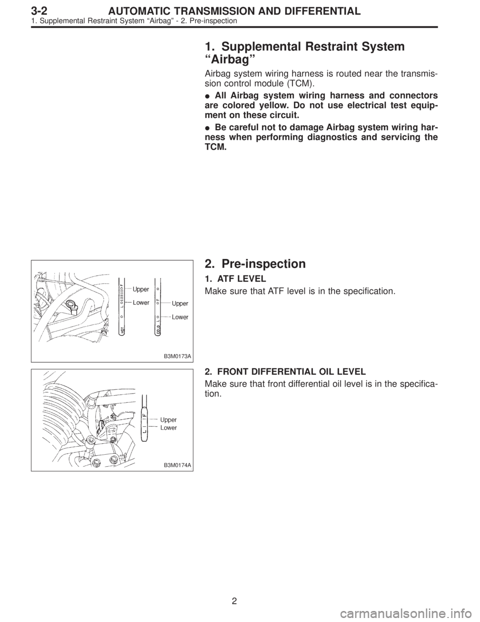
2. Pre-inspection
1. ATF LEVEL
Make sure that ATF level is in the specification.
B3M0174A
2. FRONT DIFFERENTIAL OIL LEVEL
Make sure that front differential oil level is in the specifica-
tion.
2
3-2AUTOMATIC TRANSMISSION AND DIFFERENTIAL
1. Supplemental Restraint System“Airbag”- 2. Pre-inspection
Page 2141 of 2890
1. Supplemental Restraint System
“Airbag”
Airbag system wiring harness is routed near the transmis-
sion control module (TCM).
�All Airbag system wiring harness and connectors
are colored yellow. Do not use electrical test equip-
ment on these circuit.
�Be careful not to damage Airbag system wiring har-
ness when performing diagnostics and servicing the
TCM.
B3M0173A
2. Pre-inspection
1. ATF LEVEL
Make sure that ATF level is in the specification.
B3M0174A
2. FRONT DIFFERENTIAL OIL LEVEL
Make sure that front differential oil level is in the specifica-
tion.
2
3-2AUTOMATIC TRANSMISSION AND DIFFERENTIAL
1. Supplemental Restraint System“Airbag”- 2. Pre-inspection
Page 2212 of 2890

1. Supplemental Restraint System
“Airbag”
Airbag system wiring harness is routed near the ABS/TCS
control module, ABS sensor and hydraulic control unit.
CAUTION:
�All Airbag system wiring harness and connectors
are colored yellow. Do not use electrical test equip-
ment on these circuit.
�Be careful not to damage Airbag system wiring har-
ness when servicing the ABS/TCS control module,
ABS sensor and hydraulic control unit.
2. Pre-inspection
Before performing diagnostics, check the following items
which might affect ABS/TCS problems:
A: MECHANICAL INSPECTION
1. POWER SUPPLY
1) Measure battery voltage and specific gravity of electro-
lyte.
Standard voltage: 12 V, or more
Specific gravity: Above 1.260
2) Check the condition of the main and other fuses, and
harnesses and connectors. Also check for proper ground-
ing.
2. BRAKE FLUID
1) Check brake fluid level.
2) Check brake fluid leakage.
3. BRAKE DRAG
Check brake drag.
4. BRAKE PAD AND ROTOR
Check brake pad and rotor.
5. TIRE SPECIFICATIONS, TIRE WEAR AND AIR
PRESSURE
Check tire specifications, tire wear and air pressure.
to 4-2 [S1A0].>
2
4-4bBRAKES
1. Supplemental Restraint System“Airbag”- 2. Pre-inspection
Page 2213 of 2890

1. Supplemental Restraint System
“Airbag”
Airbag system wiring harness is routed near the ABS/TCS
control module, ABS sensor and hydraulic control unit.
CAUTION:
�All Airbag system wiring harness and connectors
are colored yellow. Do not use electrical test equip-
ment on these circuit.
�Be careful not to damage Airbag system wiring har-
ness when servicing the ABS/TCS control module,
ABS sensor and hydraulic control unit.
2. Pre-inspection
Before performing diagnostics, check the following items
which might affect ABS/TCS problems:
A: MECHANICAL INSPECTION
1. POWER SUPPLY
1) Measure battery voltage and specific gravity of electro-
lyte.
Standard voltage: 12 V, or more
Specific gravity: Above 1.260
2) Check the condition of the main and other fuses, and
harnesses and connectors. Also check for proper ground-
ing.
2. BRAKE FLUID
1) Check brake fluid level.
2) Check brake fluid leakage.
3. BRAKE DRAG
Check brake drag.
4. BRAKE PAD AND ROTOR
Check brake pad and rotor.
5. TIRE SPECIFICATIONS, TIRE WEAR AND AIR
PRESSURE
Check tire specifications, tire wear and air pressure.
to 4-2 [S1A0].>
2
4-4bBRAKES
1. Supplemental Restraint System“Airbag”- 2. Pre-inspection
Page 2330 of 2890

B4M0526
Y: TROUBLE CODE 54
1. B.SW HARD
—Break and short circuit at stroke sensor or its
wiring—
DIAGNOSIS:
�Faulty stroke sensor
�Faulty harness/connector
�Faulty stop light switch
�Faulty ABS/TCS control module
TROUBLE SYMPTOM:
�ABS and TCS do not operate.
NOTE:
Operate the function F09 in select monitor TCS mode, and
read the sensor output step.
If system is normal, the output reading is 1 when brake
pedal is not depressed, and it changes from 2 to 3, 4 and
5 in accordance with the brake pedal depressing. If so, skip
check steps 1 through 5.
1. Check resistance of stroke sensor.
OK
�Not OK
Replace stroke sensor.
2. Check stroke sensor operation.
OK
�Not OK
Replace stroke sensor.
3. Check body short of stroke sensor.
OK
�Not OK
Replace stroke sensor.
4. Check harness between stroke sensor and
ABS/TCS control module.
OK
�Not OK
Repair harness/connector.
5. Check body short of stroke sensor harness.
OK
�Not OK
Repair harness.
Replace ABS/TCS control module.
�
�
�
�
�
11 9
4-4bBRAKES
10. Diagnostic Chart with Select Monitor
Page 2338 of 2890

11. General Diagnostics Table
��: Primary expected causes�: Secondary expected causes
Trouble conditions
SymptomsHydraulic
unit
Speed sensor
P valve
Master cylinder
Calipers and piston
Pad
Rotor
Hand brake
Piping
Mixture of air
Brake booster and check valve
Axle and wheel
Alignment
Play of pedal
Rough road surface
Semicylindrical road surface
Loose or worn suspension
Tire
Wrong connection and wiring
Stroke sensor Solenoid valve
Motor
Mount bush ABS function
Directional stability cannot be
obtained when braking.Vehicle turns to right or left.����������� ������������
Vehicle spins.�������������
Out-of-order brakesLong braking distance
��� ���������������
Brakes lock.������� � ��
Brakes drag.�����������������
Long pedal stroke� ���� �����
Abnormal vehicle pitching�� ������
Unstable braking force. One-
side brake refuses to work.����������� ����������
TCS function
When accelerating abruptly,
directional stability cannot be
obtained when traveling on a
slippery road surface.Vehicle moves unsteadily.������������������
Handle refuses to work.�������������
Handle loses control.���������� ���������
Bad acceleration, engine stall-
ing (In addition to the causes
listed here, check the ECM
specifications.)Engine stalls. Engine speed
fails to increase.�����������
Engine speed increases sud-
denly.��������������������
Vibration occurs and abnormal
noise is produced.
�When applying brakes abruptly.
�When accelerating abruptly.
�When driving on a slippery
road surface.Brake pedal heavily vibrates
when applying brakes.
�� � � �������
Loud hydraulic unit operating
noise��������
Noise is produced from front
of vehicle.���������������������
Noise is produced from rear of
vehicle.����������������
NOTE:
This list includes no engine failure and transmission failure.
127
4-4bBRAKES
11. General Diagnostics Table
Page 2341 of 2890

1. Supplemental Restraint System
“Airbag”
Airbag system wiring harness is routed near the ABS con-
trol module, ABS sensor and hydraulic control unit.
CAUTION:
�All Airbag system wiring harness and connectors
are colored yellow. Do not use electrical test equip-
ment on these circuit.
�Be careful not to damage Airbag system wiring har-
ness when servicing the ABS control module, ABS
sensor and hydraulic control unit.
2. Pre-inspection
Before performing diagnostics, check the following items
which might affect ABS problems:
A: MECHANICAL INSPECTION
1. POWER SUPPLY
1) Measure battery voltage and specific gravity of electro-
lyte.
Standard voltage: 12 V, or more
Specific gravity: Above 1.260
2) Check the condition of the main and other fuses, and
harnesses and connectors. Also check for proper ground-
ing.
2. BRAKE FLUID
1) Check brake fluid level.
2) Check brake fluid leakage.
3. BRAKE DRAG
Check brake drag.
4. BRAKE PAD AND ROTOR
Check brake pad and rotor.
5. TIRE SPECIFICATIONS, TIRE WEAR AND AIR
PRESSURE
Check tire specifications, tire wear and air pressure.
to 4-2 [S1A2].>
2
4-4cBRAKES [ABS 5.3 TYPE]
1. Supplemental Restraint System“Airbag”- 2. Pre-inspection
Page 2342 of 2890

1. Supplemental Restraint System
“Airbag”
Airbag system wiring harness is routed near the ABS con-
trol module, ABS sensor and hydraulic control unit.
CAUTION:
�All Airbag system wiring harness and connectors
are colored yellow. Do not use electrical test equip-
ment on these circuit.
�Be careful not to damage Airbag system wiring har-
ness when servicing the ABS control module, ABS
sensor and hydraulic control unit.
2. Pre-inspection
Before performing diagnostics, check the following items
which might affect ABS problems:
A: MECHANICAL INSPECTION
1. POWER SUPPLY
1) Measure battery voltage and specific gravity of electro-
lyte.
Standard voltage: 12 V, or more
Specific gravity: Above 1.260
2) Check the condition of the main and other fuses, and
harnesses and connectors. Also check for proper ground-
ing.
2. BRAKE FLUID
1) Check brake fluid level.
2) Check brake fluid leakage.
3. BRAKE DRAG
Check brake drag.
4. BRAKE PAD AND ROTOR
Check brake pad and rotor.
5. TIRE SPECIFICATIONS, TIRE WEAR AND AIR
PRESSURE
Check tire specifications, tire wear and air pressure.
to 4-2 [S1A2].>
2
4-4cBRAKES [ABS 5.3 TYPE]
1. Supplemental Restraint System“Airbag”- 2. Pre-inspection