Page 2074 of 2890
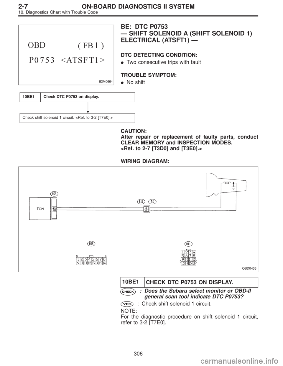
B2M0664
BE: DTC P0753
—SHIFT SOLENOID A (SHIFT SOLENOID 1)
ELECTRICAL (ATSFT1)—
DTC DETECTING CONDITION:
�Two consecutive trips with fault
TROUBLE SYMPTOM:
�No shift
10BE1Check DTC P0753 on display.
Check shift solenoid 1 circuit.
CAUTION:
After repair or replacement of faulty parts, conduct
CLEAR MEMORY and INSPECTION MODES.
WIRING DIAGRAM:
OBD0436
10BE1
CHECK DTC P0753 ON DISPLAY.
: Does the Subaru select monitor or OBD-II
general scan tool indicate DTC P0753?
: Check shift solenoid 1 circuit.
NOTE:
For the diagnostic procedure on shift solenoid 1 circuit,
refer to 3-2 [T7E0].
�
306
2-7ON-BOARD DIAGNOSTICS II SYSTEM
10. Diagnostics Chart with Trouble Code
Page 2075 of 2890
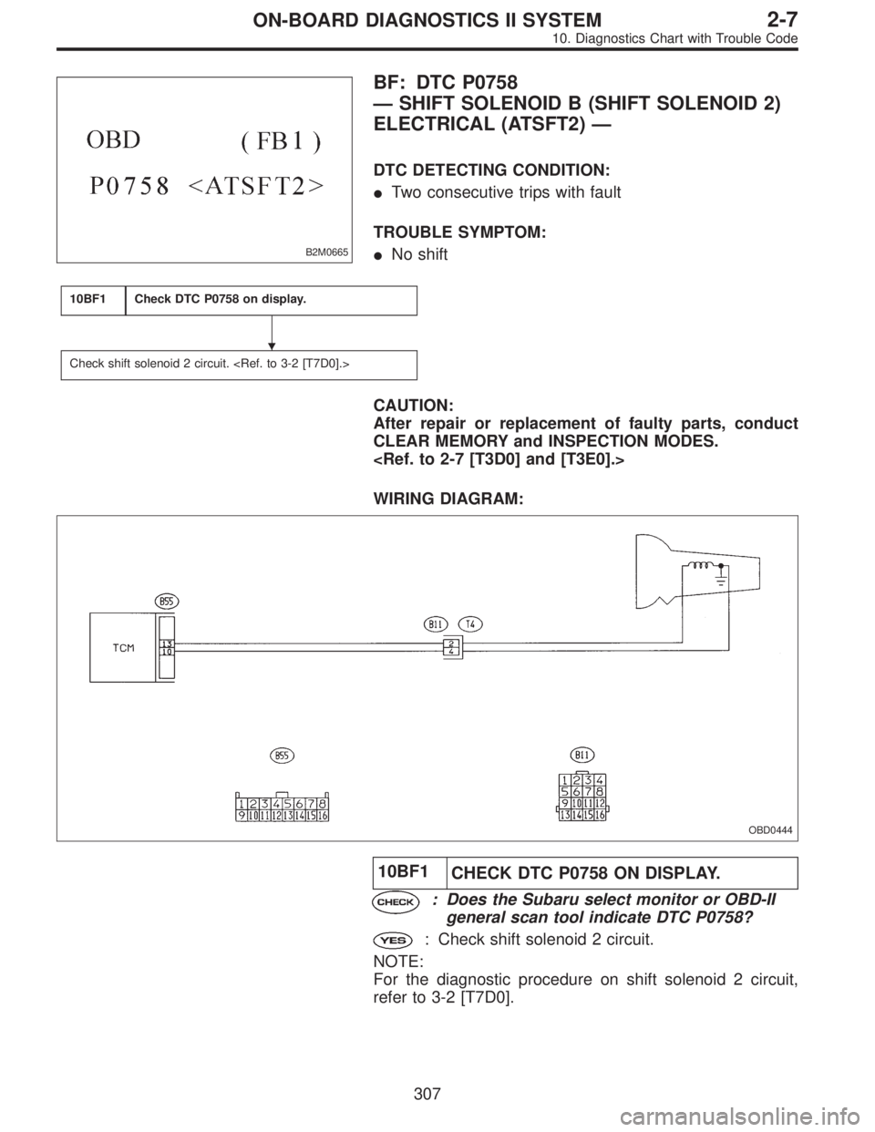
B2M0665
BF: DTC P0758
—SHIFT SOLENOID B (SHIFT SOLENOID 2)
ELECTRICAL (ATSFT2)—
DTC DETECTING CONDITION:
�Two consecutive trips with fault
TROUBLE SYMPTOM:
�No shift
10BF1Check DTC P0758 on display.
Check shift solenoid 2 circuit.
CAUTION:
After repair or replacement of faulty parts, conduct
CLEAR MEMORY and INSPECTION MODES.
WIRING DIAGRAM:
OBD0444
10BF1
CHECK DTC P0758 ON DISPLAY.
: Does the Subaru select monitor or OBD-II
general scan tool indicate DTC P0758?
: Check shift solenoid 2 circuit.
NOTE:
For the diagnostic procedure on shift solenoid 2 circuit,
refer to 3-2 [T7D0].
�
307
2-7ON-BOARD DIAGNOSTICS II SYSTEM
10. Diagnostics Chart with Trouble Code
Page 2077 of 2890
WIRING DIAGRAM:
OBD0613
10BG1CHECK ANY OTHER DTC (BESIDES DTC
P0760) ON DISPLAY.
: Is there any other DTC on display?
: Inspect relevant DTC using“10. Diagnostics Chart
with Trouble Code, 2-7 [T1000]”.
: Go to step10BG2.
10BG2
CHECK INHIBITOR SWITCH CIRCUIT.
: Is there any trouble in inhibitor switch cir-
cuit?
NOTE:
For the diagnostic procedure on inhibitor switch circuit,
refer to 2-7 [T10AT0].
: Repair or replace inhibitor switch circuit.
: Go to step10BG3.
309
2-7ON-BOARD DIAGNOSTICS II SYSTEM
10. Diagnostics Chart with Trouble Code
Page 2080 of 2890
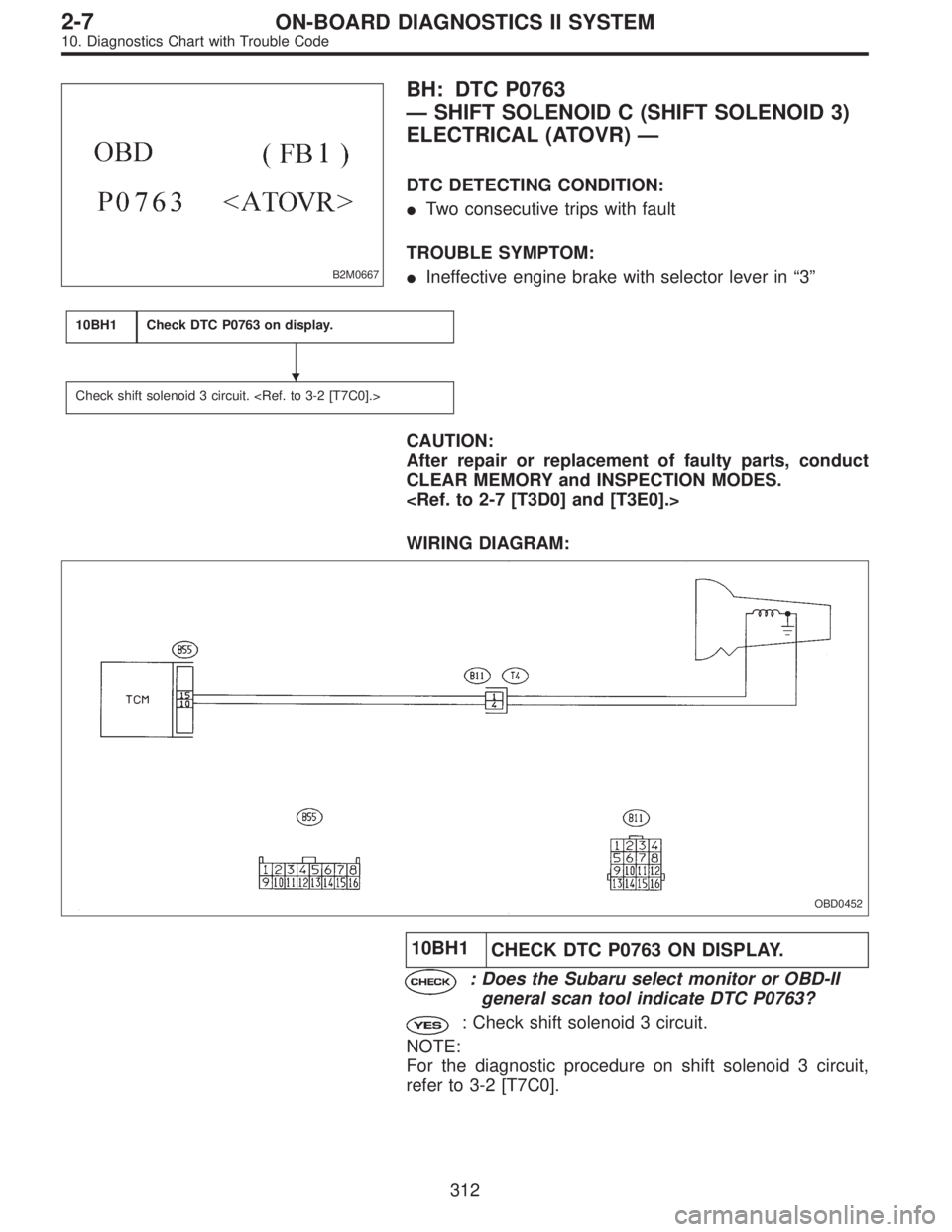
B2M0667
BH: DTC P0763
—SHIFT SOLENOID C (SHIFT SOLENOID 3)
ELECTRICAL (ATOVR)—
DTC DETECTING CONDITION:
�Two consecutive trips with fault
TROUBLE SYMPTOM:
�Ineffective engine brake with selector lever in“3”
10BH1Check DTC P0763 on display.
Check shift solenoid 3 circuit.
CAUTION:
After repair or replacement of faulty parts, conduct
CLEAR MEMORY and INSPECTION MODES.
WIRING DIAGRAM:
OBD0452
10BH1
CHECK DTC P0763 ON DISPLAY.
: Does the Subaru select monitor or OBD-II
general scan tool indicate DTC P0763?
: Check shift solenoid 3 circuit.
NOTE:
For the diagnostic procedure on shift solenoid 3 circuit,
refer to 3-2 [T7C0].
�
312
2-7ON-BOARD DIAGNOSTICS II SYSTEM
10. Diagnostics Chart with Trouble Code
Page 2081 of 2890
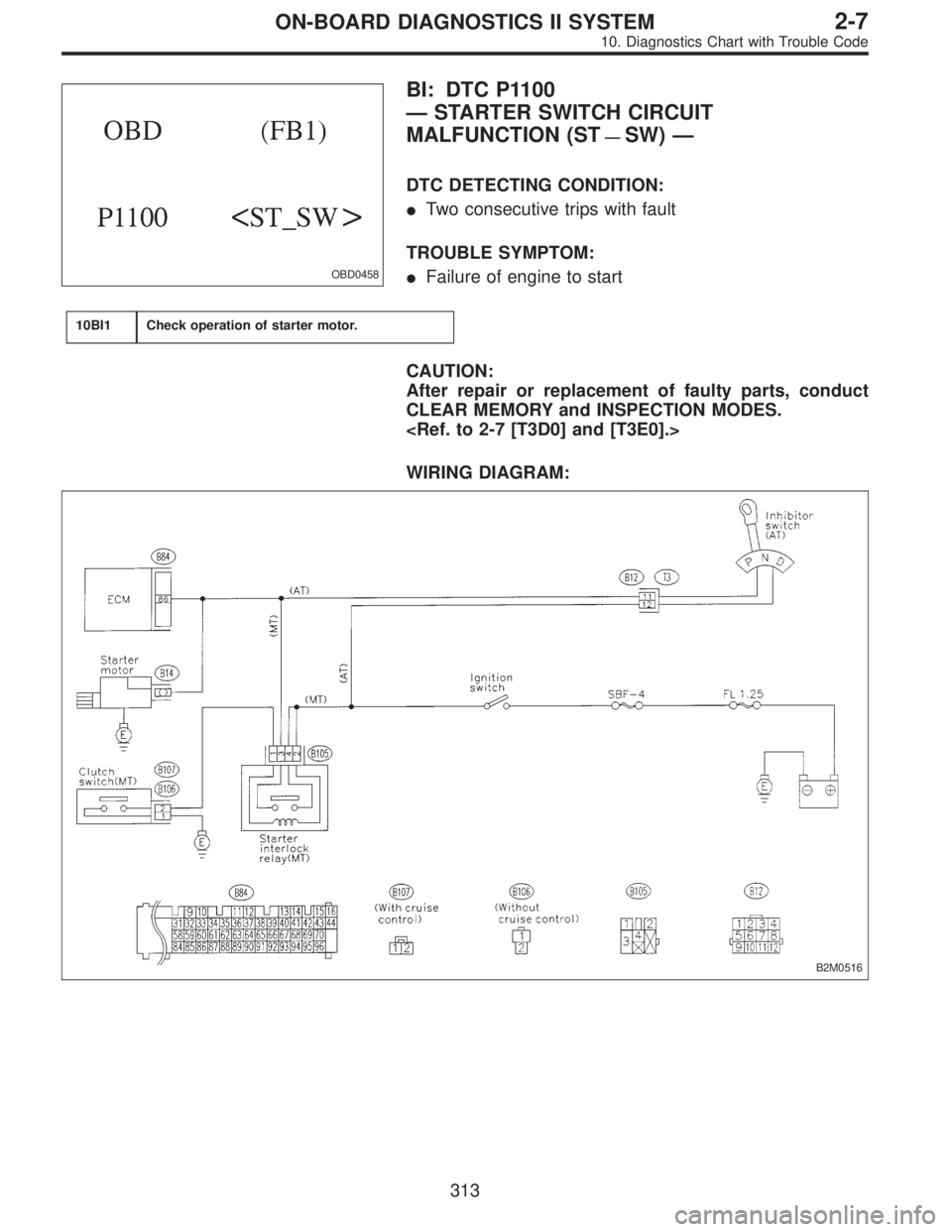
OBD0458
BI: DTC P1100
—STARTER SWITCH CIRCUIT
MALFUNCTION (ST
—SW)—
DTC DETECTING CONDITION:
�Two consecutive trips with fault
TROUBLE SYMPTOM:
�Failure of engine to start
10BI1Check operation of starter motor.
CAUTION:
After repair or replacement of faulty parts, conduct
CLEAR MEMORY and INSPECTION MODES.
WIRING DIAGRAM:
B2M0516
313
2-7ON-BOARD DIAGNOSTICS II SYSTEM
10. Diagnostics Chart with Trouble Code
Page 2083 of 2890
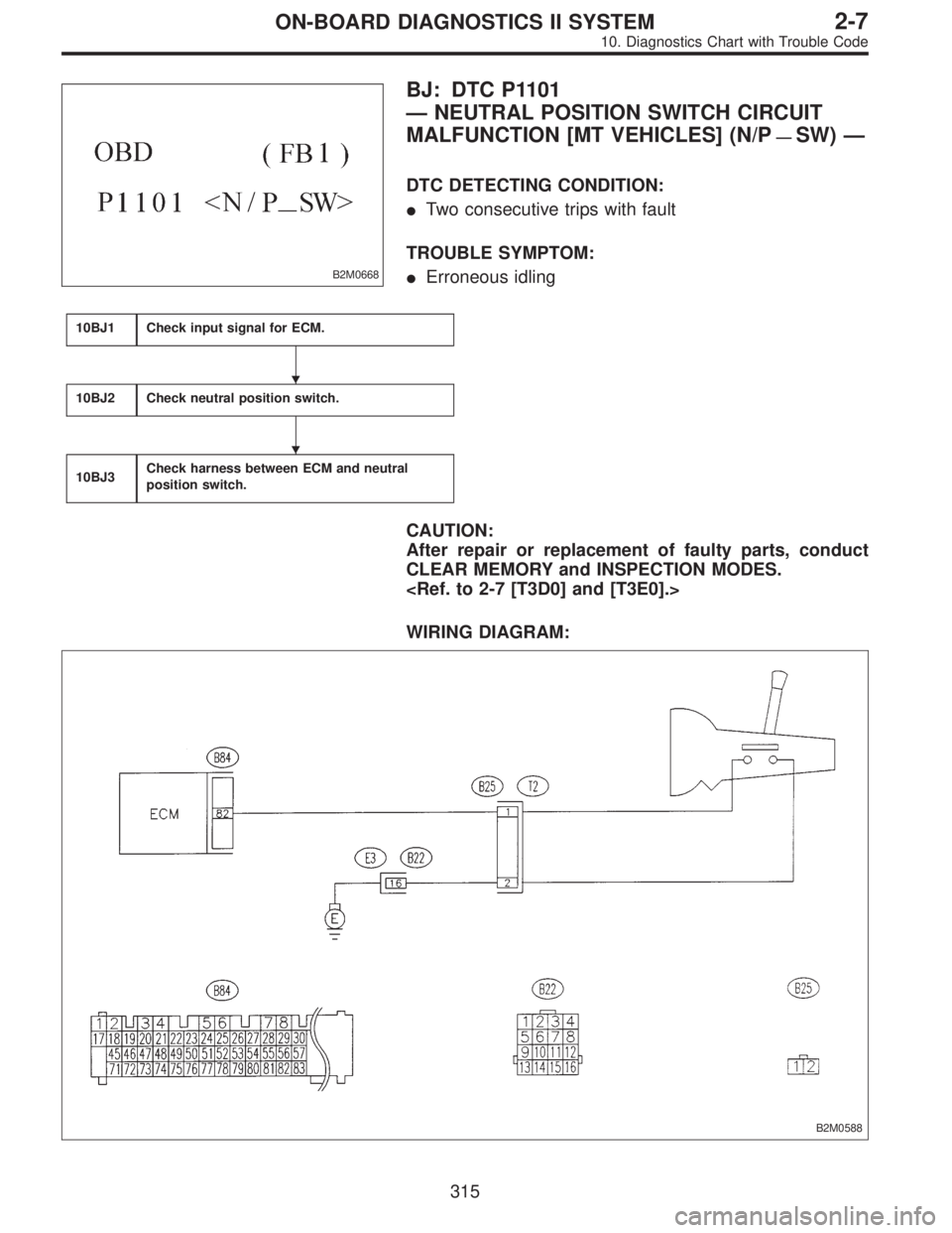
B2M0668
BJ: DTC P1101
—NEUTRAL POSITION SWITCH CIRCUIT
MALFUNCTION [MT VEHICLES] (N/P
—SW)—
DTC DETECTING CONDITION:
�Two consecutive trips with fault
TROUBLE SYMPTOM:
�Erroneous idling
10BJ1Check input signal for ECM.
10BJ2Check neutral position switch.
10BJ3Check harness between ECM and neutral
position switch.
CAUTION:
After repair or replacement of faulty parts, conduct
CLEAR MEMORY and INSPECTION MODES.
WIRING DIAGRAM:
B2M0588
�
�
315
2-7ON-BOARD DIAGNOSTICS II SYSTEM
10. Diagnostics Chart with Trouble Code
Page 2087 of 2890
WIRING DIAGRAM:
B2M0592
B2M0593A
10BK1
CHECK INPUT SIGNAL FOR ECM.
1) Turn ignition switch to ON.
2) Measure voltage between ECM and chassis ground.
: Connector & terminal
(B84) No. 82 (+)—Chassis ground (�):
Is the voltage less than1Vin“N”and“P”
positions?
: Go to next.
: Go to step10BK2.
B2M0593A
: Connector & terminal
(B84) No. 82 (+)—Chassis ground (�):
Is the voltage between 4.5 and 5.5 V in other
positions?
: Go to next.
: Go to step10BK2.
: Is there poor contact in ECM connector?
: Repair poor contact in ECM connector.
: Replace ECM.
319
2-7ON-BOARD DIAGNOSTICS II SYSTEM
10. Diagnostics Chart with Trouble Code
Page 2091 of 2890
WIRING DIAGRAM:
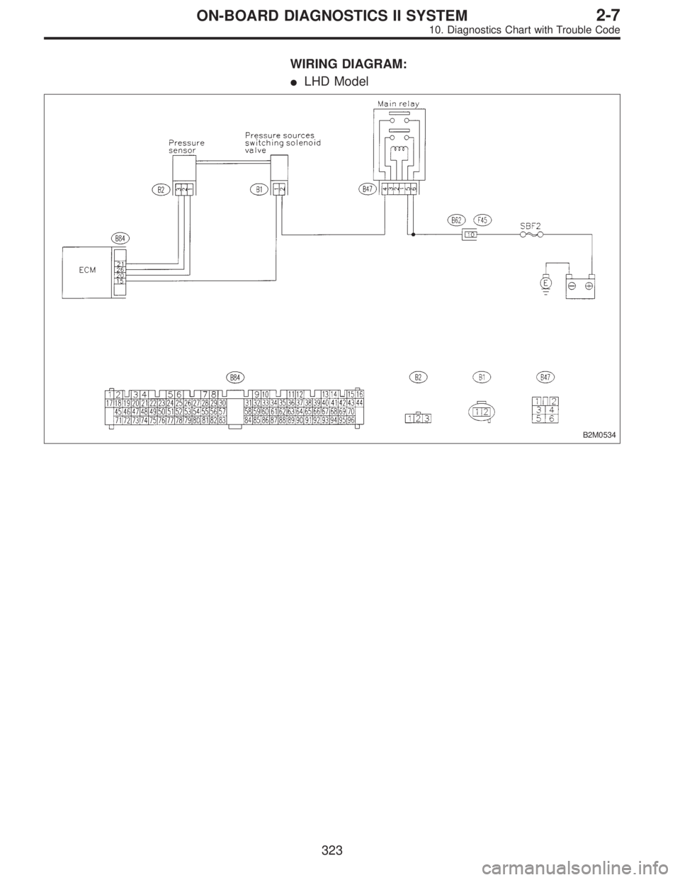
�LHD Model
B2M0534
323
2-7ON-BOARD DIAGNOSTICS II SYSTEM
10. Diagnostics Chart with Trouble Code
 ON DISPLAY.
: Is there any other DTC on display?
: Inspect relevant DTC using“10. Diagnostics Chart
with Trouble Code, 2-7 [T1000")
 Turn ignition switch to ON.
2) Measure voltage between ECM and chassis ground.
: Connector & terminal
(B84) No. 82 (+)—Chassis g")