Page 2354 of 2890
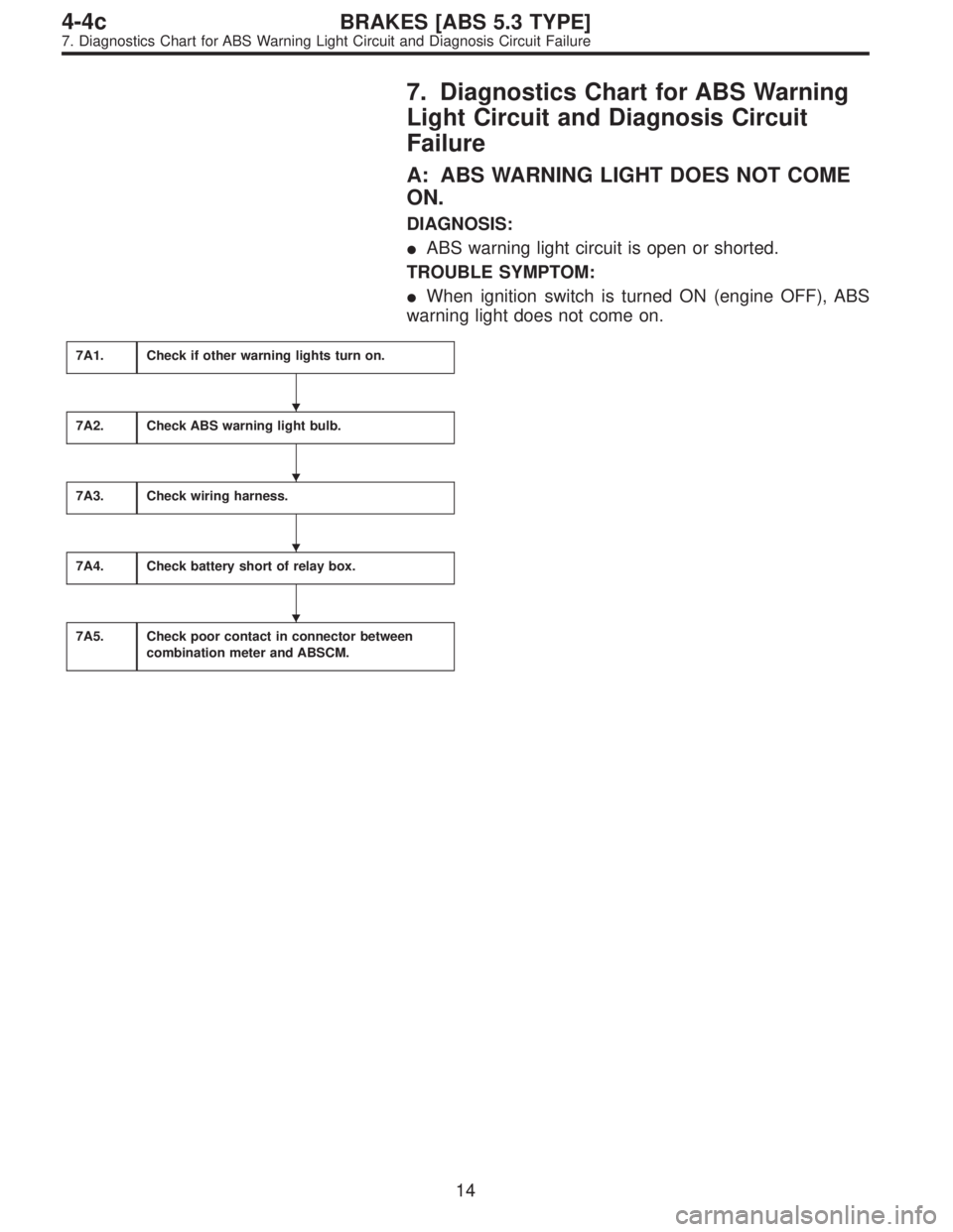
7. Diagnostics Chart for ABS Warning
Light Circuit and Diagnosis Circuit
Failure
A: ABS WARNING LIGHT DOES NOT COME
ON.
DIAGNOSIS:
�ABS warning light circuit is open or shorted.
TROUBLE SYMPTOM:
�When ignition switch is turned ON (engine OFF), ABS
warning light does not come on.
7A1.Check if other warning lights turn on.
7A2.Check ABS warning light bulb.
7A3.Check wiring harness.
7A4.Check battery short of relay box.
7A5.Check poor contact in connector between
combination meter and ABSCM.
�
�
�
�
14
4-4cBRAKES [ABS 5.3 TYPE]
7. Diagnostics Chart for ABS Warning Light Circuit and Diagnosis Circuit Failure
Page 2355 of 2890
WIRING DIAGRAM:
B4M1034
7A1CHECK IF OTHER WARNING LIGHTS
TURN ON.
Turn ignition switch to ON (engine OFF).
: Do other warning lights turn on?
: Go to step7A2.
: Repair combination meter.
15
4-4cBRAKES [ABS 5.3 TYPE]
7. Diagnostics Chart for ABS Warning Light Circuit and Diagnosis Circuit Failure
Page 2356 of 2890
7A2
CHECK ABS WARNING LIGHT BULB.
1) Turn ignition switch to OFF.
2) Remove combination meter.
3) Remove ABS warning light bulb from combination
meter.
: Is ABS warning light bulb OK?
: Go to step7A3.
: Replace ABS warning light bulb.
B4M0791A
7A3
CHECK WIRING HARNESS.
1) Disconnect connector from ABSCM.
2) Disconnect connector (F50) from relay box.
3) Turn ignition switch to ON.
4) Measure voltage between connector (F49) and chassis
ground.
: Connector & terminal
(F49) No. 54 (+) — Chassis ground (�):
Is voltage 12 V?
: Go to next step.
: Repair broken wire in harness or connector.
5) Turn ignition switch to OFF.
6) Measure voltage between ABSCM connector (F49) and
chassis ground.
: Connector & terminal
(F49) No. 54 (+) — Chassis ground (�):
Is voltage less than 3 V?
: Go to step7A4.
: Repair battery short of harness.
16
4-4cBRAKES [ABS 5.3 TYPE]
7. Diagnostics Chart for ABS Warning Light Circuit and Diagnosis Circuit Failure
Page 2358 of 2890
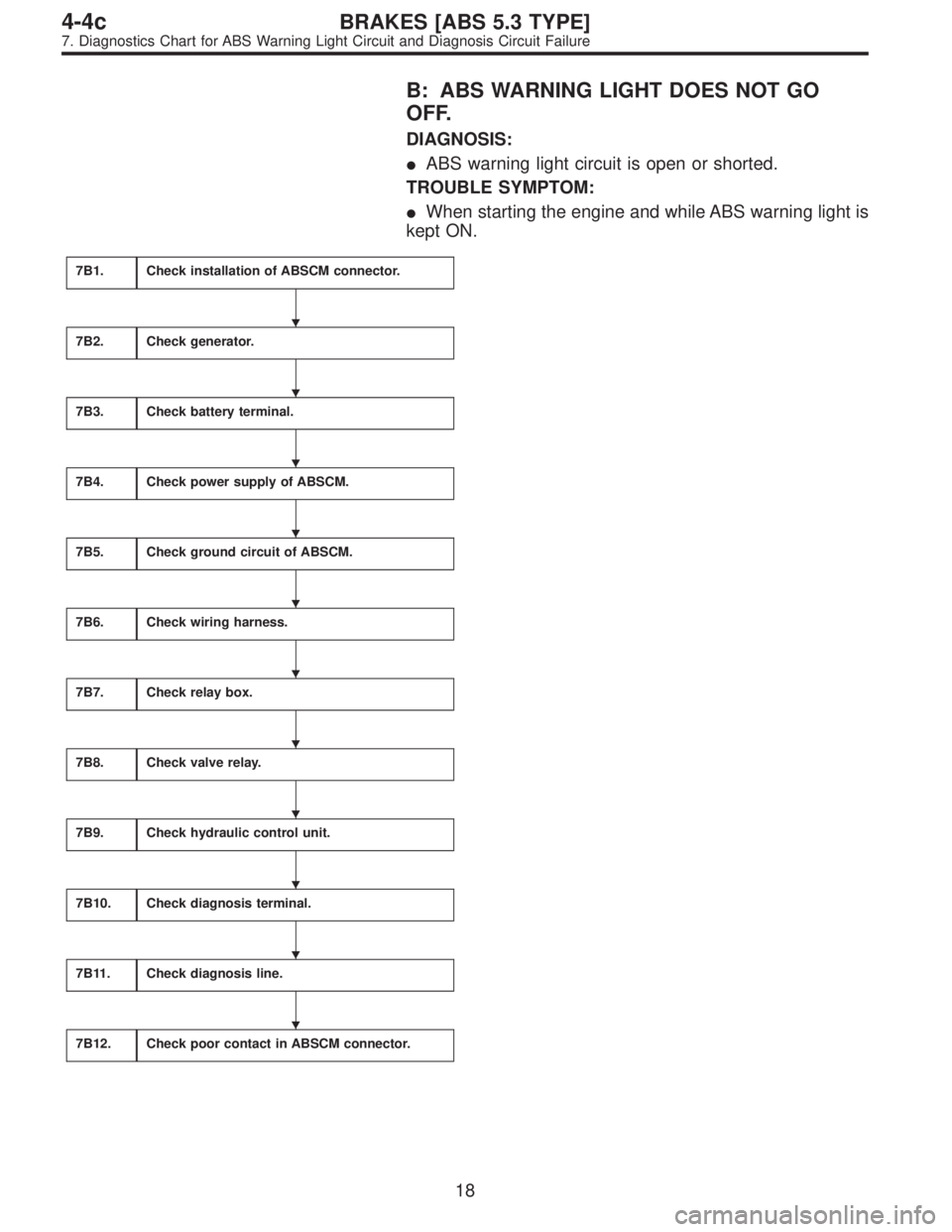
B: ABS WARNING LIGHT DOES NOT GO
OFF.
DIAGNOSIS:
�ABS warning light circuit is open or shorted.
TROUBLE SYMPTOM:
�When starting the engine and while ABS warning light is
kept ON.
7B1.Check installation of ABSCM connector.
7B2.Check generator.
7B3.Check battery terminal.
7B4.Check power supply of ABSCM.
7B5.Check ground circuit of ABSCM.
7B6.Check wiring harness.
7B7.Check relay box.
7B8.Check valve relay.
7B9.Check hydraulic control unit.
7B10.Check diagnosis terminal.
7B11.Check diagnosis line.
7B12.Check poor contact in ABSCM connector.
�
�
�
�
�
�
�
�
�
�
�
18
4-4cBRAKES [ABS 5.3 TYPE]
7. Diagnostics Chart for ABS Warning Light Circuit and Diagnosis Circuit Failure
Page 2359 of 2890
WIRING DIAGRAM:
B4M1034
7B1CHECK INSTALLATION OF ABSCM CON-
NECTOR.
Turn ignition switch to OFF.
: Is ABSCM connector inserted into ABSCM
until the clamp locks onto it?
: Go to step7B2.
: Insert ABSCM connector into ABSCM until the
clamp locks onto it.
19
4-4cBRAKES [ABS 5.3 TYPE]
7. Diagnostics Chart for ABS Warning Light Circuit and Diagnosis Circuit Failure
Page 2361 of 2890
B4M0797A
7B5
CHECK GROUND CIRCUIT OF ABSCM.
1) Turn ignition switch to OFF.
2) Measure resistance between ABSCM connector and
chassis ground.
: Connector & terminal
(F49) No. 1—Chassis ground:
(F49) No. 55—Chassis ground:
Is resistance less than 0.5Ω?
: Go to step7B6.
: Repair ABSCM ground harness.
7B6
CHECK WIRING HARNESS.
1) Disconnect connector (F50) from relay box.
2) Turn ignition switch to ON.
: Does the ABS warning light remain off?
: Go to step7B7.
: Repair front wiring harness.
7B7
CHECK RELAY BOX.
1) Turn ignition switch to OFF.
2) Connect connector (F50) to relay box.
3) Remove valve relay from relay box.
4) Disconnect connector (ABS1) from hydraulic control
unit.
5) Turn ignition switch to ON.
: Does the ABS warning light remain off?
: Go to step7B8.
: Repair relay box and check fuse.
21
4-4cBRAKES [ABS 5.3 TYPE]
7. Diagnostics Chart for ABS Warning Light Circuit and Diagnosis Circuit Failure
Page 2365 of 2890
WIRING DIAGRAM:
B4M1034
B4M0800A
7C1
CHECK DIAGNOSIS TERMINAL.
Measure resistance between diagnosis terminals (B81)
and chassis ground.
: Terminals
Diagnosis terminal (A)—Chassis ground:
Diagnosis terminal (B)—Chassis ground:
Is the resistance less than 0.5Ω?
: Go to step7C2.
: Repair diagnosis terminal harness.
25
4-4cBRAKES [ABS 5.3 TYPE]
7. Diagnostics Chart for ABS Warning Light Circuit and Diagnosis Circuit Failure
Page 2369 of 2890
WIRING DIAGRAM:
B4M1035
29
4-4cBRAKES [ABS 5.3 TYPE]
8. Diagnostics Chart with Trouble Code
.
: Do other warning lights turn on?
: Go to step7A2.
: Repair combination meter.
15
4-4cBRAKES")
 Turn ignition switch to OFF.
2) Remove combination meter.
3) Remove ABS warning light bulb from combination
meter.
: Is ABS warning light bulb OK?
: Go to step7A3.")

 Turn ignition switch to OFF.
2) Measure resistance between ABSCM connector and
chassis ground.
: Connector & terminal
(F49) No. 1—Chassis ground:
(F49)")

and chassis ground.
: Terminals
Diagnosis terminal (A)—Chassis ground:
Diagnosis t")
![SUBARU LEGACY 1996 Service Repair Manual WIRING DIAGRAM:
B4M1035
29
4-4cBRAKES [ABS 5.3 TYPE]
8. Diagnostics Chart with Trouble Code](/manual-img/17/57433/w960_57433-2368.png "SUBARU LEGACY 1996 Service Repair Manual WIRING DIAGRAM:
B4M1035
29
4-4cBRAKES [ABS 5.3 TYPE]
8. Diagnostics Chart with Trouble Code")