Page 1256 of 2890
6. Brake Booster
A: REMOVAL
1) Remove or disconnect the following parts at engine
compartment.
(1) Disconnect connector for brake fluid level indicator.
(2) Remove brake pipes from master cylinder.
(3) Remove master cylinder installing nuts.
(4) Disconnect vacuum hose from brake booster.
2) Remove the following parts from the pedal bracket.
(1) Snap pin and clevis pin
(2) Four brake booster installing nuts
3) Remove brake booster while shunning brake pipes.
B4M0117A
B: INSTALLATION
1) Mount brake booster in position.
2) Connect operating rod to brake pedal with clevis pin
and snap pin.
�
1Clevis pin
�
2Snap pin
�
3Operating rod
G4M0420
3) Connect vacuum hose to brake booster.
4) Mount master cylinder onto brake booster.
5) Connect brake pipes to master cylinder.
6) Connect electric connector for brake fluid level indica-
tor.
50
4-4SERVICE PROCEDURE
6. Brake Booster
Page 1298 of 2890
 Check the pedal stroke.
While the engine is idling, depress the brake pedal with a
490 N (50 kg, 110 lb) load and measure the distance
between the brake pedal and steering wheel. With the")
G4M0436
16) Check the pedal stroke.
While the engine is idling, depress the brake pedal with a
490 N (50 kg, 110 lb) load and measure the distance
between the brake pedal and steering wheel. With the
brake pedal released, measure the distance between the
pedal and steering wheel again. The difference between
the two measurements must be less than specified.
Specified pedal stroke:
With TCS
95 mm (3.74 in)
When depressing brake pedal with a 490 N (50 kg,
110 lb) load.
If the distance is more than specifications, there is a
possibility that air is in the brake line. Bleed air from the
brake line.
17) Turn ignition switch OFF.
18) Disconnect select monitor or diagnosis terminal.
19) Add brake fluid to the required level (MAX. level) of
reserve tank.
20) As a final step, test run the vehicle at low speed and
apply brakes relatively hard 2 to 3 times to ensure that
brakes provide normal braking action on all four wheels
without dragging and uneven braking.
2. CONDITIONS FOR AIR BLEEDING CONTROL
Stop light
switchTCS OFF
switchPump
motorTCS
valveFRO
RLOFLO
RROTCS
operating
indicator
lightABS
warning
lightTCS
warning
light
Air
bleeding
control is
operating.OFF ON ON Close Close Close ON ON ON
ON ON OFF Open Open Close ON ON OFF
ON ON OFF Open Close Open ON OFF ON
ON or OFF OFF OFF Open Close Close ON OFF OFF
Stops tem-
porarily.*——OFF Open Close Close OFF OFF OFF
Prohibited.——OFF Open Close Close OFF ON ON
*: When brake fluid level switch detects brake fluid in LOW level, control operation stops temporarily. After refilling brake fluid, operation
re-starts.
89
4-4SERVICE PROCEDURE
19. Air Bleeding (With TCS model)
Page 1299 of 2890

3. CONDITIONS FOR COMPLETION OF AIR
BLEEDING CONTROL
When any of the following conditions occurs, ABS and TCS
warning lights illuminate. Air bleeding control stops, while
the ABS and TCS function will then stop. The brake sys-
tem functions as a conventional brake system.
1) When the speed of at least one wheel reaches 10 km/h
(6 MPH).
2) When terminal No. 4 is separated from diagnosis termi-
nal. (When select monitor is not used.)
3) When pump motor remains ON for two minutes.
4) When TCS valve remains open for two minutes.
5) When outlet valve remains closed for two minutes.
6) When malfunction is detected.
NOTE:
When a malfunction is detected the air bleeding operation
stops and the trouble codes are stored in memory.
B4M0082C
C: AIR BLEEDING CONTROL WITH
DIAGNOSIS CONNECTOR
1) Connect diagnosis terminals to terminal No. 4 of the
diagnosis connector beside driver’s seat heater unit.
B4M0621A
2) Start the engine while pushing TCS OFF switch.
NOTE:
Keep the TCS OFF switch depressed even after the engine
has started.
3) After ABS and TCS warning lights go out, depress
brake pedal within 0.5 seconds.
4) After ensuring TCS ON indicator illuminates, release
TCS OFF switch and brake pedal.
5) Air bleeding control operation starts.
90
4-4SERVICE PROCEDURE
19. Air Bleeding (With TCS model)
Page 1661 of 2890
![SUBARU LEGACY 1996 Service Repair Manual CAUTION:
�Observe the items in 1. NORMAL CHARGING 6-2
[W2C1].
�Never use more than 10 amperes when charging the
battery because that will shorten battery life.
3. JUDGMENT OF BATTERY IN CHARGED
CONDIT](/manual-img/17/57433/w960_57433-1660.png "SUBARU LEGACY 1996 Service Repair Manual CAUTION:
�Observe the items in 1. NORMAL CHARGING 6-2
[W2C1].
�Never use more than 10 amperes when charging the
battery because that will shorten battery life.
3. JUDGMENT OF BATTERY IN CHARGED
CONDIT")
CAUTION:
�Observe the items in 1. NORMAL CHARGING 6-2
[W2C1].
�Never use more than 10 amperes when charging the
battery because that will shorten battery life.
3. JUDGMENT OF BATTERY IN CHARGED
CONDITION
1) Specific gravity of electrolyte is held at a specific value
in a range from 1.250 to 1.290 for more than one hour.
2) Voltage per battery cell is held at a specific value in a
range from 2.5 to 2.8 volts for more than one hour.
4. CHECK HYDROMETER FOR STATE OF CHARGE
Hydrometer indicator State of charge Required action
Green dot Above 65% Load test
Dark dot Below 65% Charge battery
Clear dot Low electrolyteReplace battery.* (If
cranking complaint)
*: Check electrical system before replacement.
B6M0236
3. Ignition Switch
A: REMOVAL AND INSTALLATION
1. IGNITION SWITCH
1) Remove screws, separate upper column cover and
lower column cover.
2) Remove instrument panel lower cover.
B6M0333
3) Disconnect ignition switch connector from body har-
ness.
4) Using a drift and hammer, hit the torn bolt head to
loosen and remove the ignition switch.
B6M0334A
5) When installing, tighten the connecting bolt until its
head twists off.
7
6-2SERVICE PROCEDURE
2. Battery - 3. Ignition Switch
Page 1662 of 2890
![SUBARU LEGACY 1996 Service Repair Manual CAUTION:
�Observe the items in 1. NORMAL CHARGING 6-2
[W2C1].
�Never use more than 10 amperes when charging the
battery because that will shorten battery life.
3. JUDGMENT OF BATTERY IN CHARGED
CONDIT](/manual-img/17/57433/w960_57433-1661.png "SUBARU LEGACY 1996 Service Repair Manual CAUTION:
�Observe the items in 1. NORMAL CHARGING 6-2
[W2C1].
�Never use more than 10 amperes when charging the
battery because that will shorten battery life.
3. JUDGMENT OF BATTERY IN CHARGED
CONDIT")
CAUTION:
�Observe the items in 1. NORMAL CHARGING 6-2
[W2C1].
�Never use more than 10 amperes when charging the
battery because that will shorten battery life.
3. JUDGMENT OF BATTERY IN CHARGED
CONDITION
1) Specific gravity of electrolyte is held at a specific value
in a range from 1.250 to 1.290 for more than one hour.
2) Voltage per battery cell is held at a specific value in a
range from 2.5 to 2.8 volts for more than one hour.
4. CHECK HYDROMETER FOR STATE OF CHARGE
Hydrometer indicator State of charge Required action
Green dot Above 65% Load test
Dark dot Below 65% Charge battery
Clear dot Low electrolyteReplace battery.* (If
cranking complaint)
*: Check electrical system before replacement.
B6M0236
3. Ignition Switch
A: REMOVAL AND INSTALLATION
1. IGNITION SWITCH
1) Remove screws, separate upper column cover and
lower column cover.
2) Remove instrument panel lower cover.
B6M0333
3) Disconnect ignition switch connector from body har-
ness.
4) Using a drift and hammer, hit the torn bolt head to
loosen and remove the ignition switch.
B6M0334A
5) When installing, tighten the connecting bolt until its
head twists off.
7
6-2SERVICE PROCEDURE
2. Battery - 3. Ignition Switch
Page 1695 of 2890
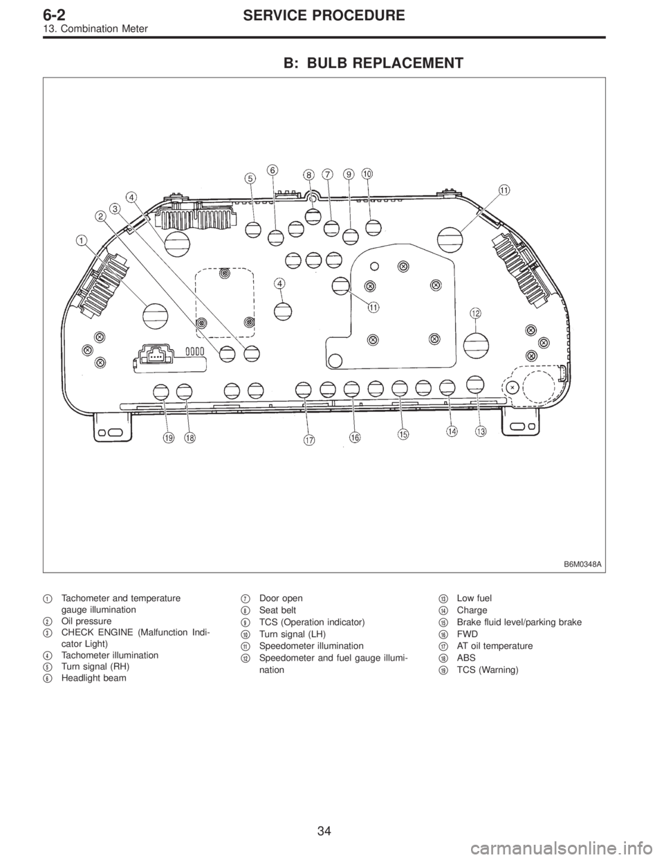
B: BULB REPLACEMENT
B6M0348A
�1Tachometer and temperature
gauge illumination
�
2Oil pressure
�
3CHECK ENGINE (Malfunction Indi-
cator Light)
�
4Tachometer illumination
�
5Turn signal (RH)
�
6Headlight beam�
7Door open
�
8Seat belt
�
9TCS (Operation indicator)
�
10Turn signal (LH)
�
11Speedometer illumination
�
12Speedometer and fuel gauge illumi-
nation�
13Low fuel
�
14Charge
�
15Brake fluid level/parking brake
�
16FWD
�
17AT oil temperature
�
18ABS
�
19TCS (Warning)
34
6-2SERVICE PROCEDURE
13. Combination Meter
Page 1714 of 2890
 Remove door lock timer�1while disconnecting connec-
tor.
B6M0684A
4) Remove cruise control module�1while disconnecting
connector.
5) Installation is in the reverse order of removal.
Tighte")
B6M0683A
3) Remove door lock timer�1while disconnecting connec-
tor.
B6M0684A
4) Remove cruise control module�1while disconnecting
connector.
5) Installation is in the reverse order of removal.
Tightening torque:
7.4±2.5 N⋅m (0.75±0.25 kg-m, 5.4±1.8 ft-lb)
C: DRIVING TESTS
Conduct road tests by selecting a smooth, flat road or use
free rollers as road test simulation.
1. MAIN SWITCH
1) Turn ignition switch ON.
2) Check that indicator light comes on when main switch
is pressed (ON).
3) Check that indicator light goes out when main switch is
pressed again (OFF).
4) Turn ignition switch OFF with main switch ON (which is
indicated by illumination.).
5) Turn ignition switch ON again to ensure that indicator
light remains OFF.
2. COMMAND SWITCH
1) Check that command switch is properly set in“SET/
COAST”,“RESUME/ACCEL”or“CANCEL”mode.
2) Also check that command switch returns to the original
position when released.
3. CONSTANT SPEED TEST
1) Turn main switch ON.
2) Drive vehicle at speed greater than 40 km/h (25 MPH).
3) Press command switch to set in“SET/COAST”mode.
4) Ensure that vehicle is maintained at the speed set when
command switch was pressed.
4. ACCELERATION TEST
1) Set vehicle speed at speed greater than 40 km/h (25
MPH).
50
6-2SERVICE PROCEDURE
21. Cruise Control
Page 1719 of 2890

NOTE:
The rear gate switch is united with the rear gate latch
assembly.
1) Remove rear gate trim panel.
2) Disconnect rod from rear gate latch assembly.
3) Disconn")
B6M0372A
8. REAR GATE SWITCH (WAGON)
NOTE:
The rear gate switch is united with the rear gate latch
assembly.
1) Remove rear gate trim panel.
2) Disconnect rod from rear gate latch assembly.
3) Disconnect rear gate switch (combined with luggage
room light switch) connector and power door lock actuator
connector.
4) Remove bolts which secure power door lock actuator.
5) Remove bolts which secure latch.
6) Remove latch and actuator assembly.
7) Installation is in the reverse order of removal.
B6M0373A
9. SECURITY INDICATOR LIGHT
1) Remove screws which secure meter visor.
2) Remove meter visor from instrument panel while dis-
connecting connectors.
3) Remove security indicator light from meter visor.
4) Installation is in the reverse order of removal.
B6M0685A
10. SECURITY CONTROL MODULE
1) Remove instrument panel.
2) Remove bolt which secures security control module�
1.
3) Remove security control module while disconnecting
connector.
4) Installation is in the reverse order of removal.
Tightening torque:
7.4±2.0 N⋅m (0.75±0.2 kg-m, 5.4±1.4 ft-lb)
55
6-2SERVICE PROCEDURE
22. Security System
 Remove or disconnect the following parts at engine
compartment.
(1) Disconnect connector for brake fluid level indicator.
(2) Remove brake pipes from master cylinder.
(3")