Page 1735 of 2890
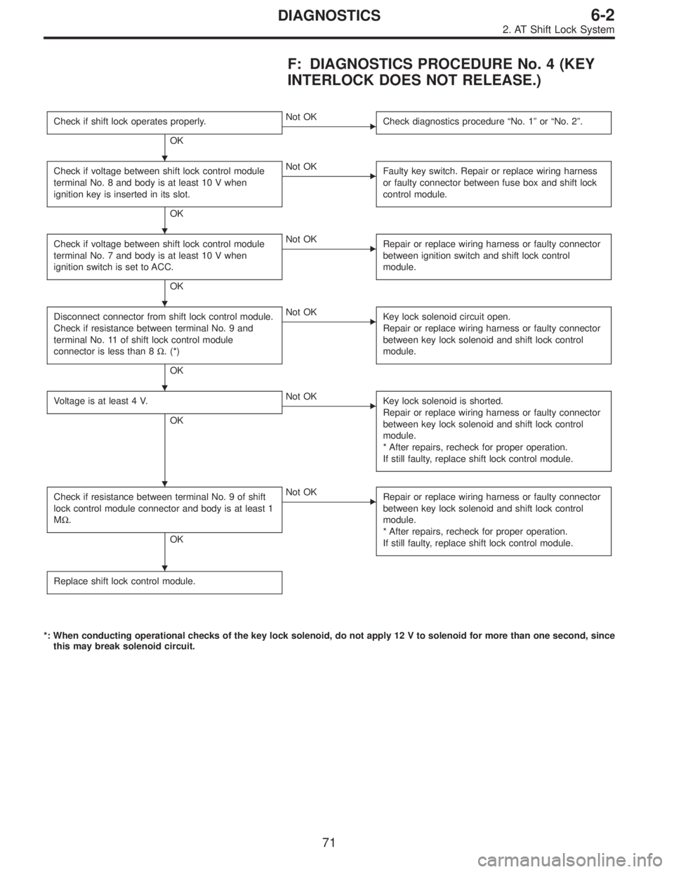
F: DIAGNOSTICS PROCEDURE No. 4 (KEY
INTERLOCK DOES NOT RELEASE.)
Check if shift lock operates properly.
OK
�Not OK
Check diagnostics procedure“No. 1”or“No. 2”.
Check if voltage between shift lock control module
terminal No. 8 and body is at least 10 V when
ignition key is inserted in its slot.
OK
�Not OK
Faulty key switch. Repair or replace wiring harness
or faulty connector between fuse box and shift lock
control module.
Check if voltage between shift lock control module
terminal No. 7 and body is at least 10 V when
ignition switch is set to ACC.
OK
�Not OK
Repair or replace wiring harness or faulty connector
between ignition switch and shift lock control
module.
Disconnect connector from shift lock control module.
Check if resistance between terminal No. 9 and
terminal No. 11 of shift lock control module
connector is less than 8Ω. (*)
OK
�Not OK
Key lock solenoid circuit open.
Repair or replace wiring harness or faulty connector
between key lock solenoid and shift lock control
module.
Voltage is at least 4 V.
OK
�Not OK
Key lock solenoid is shorted.
Repair or replace wiring harness or faulty connector
between key lock solenoid and shift lock control
module.
* After repairs, recheck for proper operation.
If still faulty, replace shift lock control module.
Check if resistance between terminal No. 9 of shift
lock control module connector and body is at least 1
MΩ.
OK
�Not OK
Repair or replace wiring harness or faulty connector
between key lock solenoid and shift lock control
module.
* After repairs, recheck for proper operation.
If still faulty, replace shift lock control module.
Replace shift lock control module.
*: When conducting operational checks of the key lock solenoid, do not apply 12 V to solenoid for more than one second, since
this may break solenoid circuit.
�
�
�
�
�
�
71
6-2DIAGNOSTICS
2. AT Shift Lock System
Page 1755 of 2890
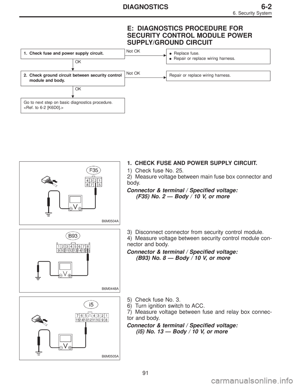
E: DIAGNOSTICS PROCEDURE FOR
SECURITY CONTROL MODULE POWER
SUPPLY/GROUND CIRCUIT
1. Check fuse and power supply circuit.
OK
�Not OK
�Replace fuse.
�Repair or replace wiring harness.
2. Check ground circuit between security control
module and body.
OK
�Not OK
Repair or replace wiring harness.
Go to next step on basic diagnostics procedure.
B6M0504A
1. CHECK FUSE AND POWER SUPPLY CIRCUIT.
1) Check fuse No. 25.
2) Measure voltage between main fuse box connector and
body.
Connector & terminal / Specified voltage:
(F35) No. 2—Body / 10 V, or more
B6M0448A
3) Disconnect connector from security control module.
4) Measure voltage between security control module con-
nector and body.
Connector & terminal / Specified voltage:
(B93) No. 8—Body / 10 V, or more
B6M0505A
5) Check fuse No. 3.
6) Turn ignition switch to ACC.
7) Measure voltage between fuse and relay box connec-
tor and body.
Connector & terminal / Specified voltage:
(i5) No. 13—Body / 10 V, or more
�
�
91
6-2DIAGNOSTICS
6. Security System
Page 1859 of 2890
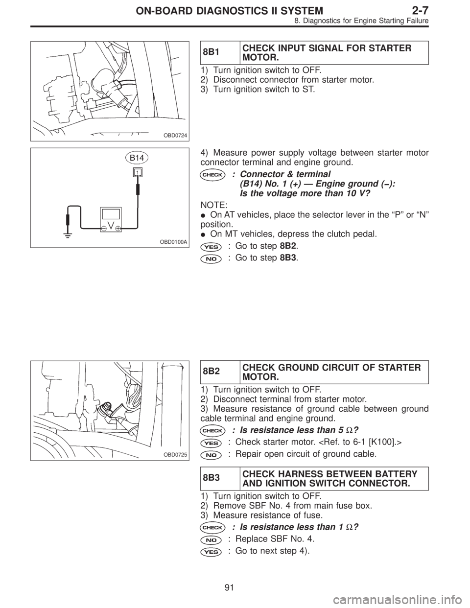
OBD0724
8B1CHECK INPUT SIGNAL FOR STARTER
MOTOR.
1) Turn ignition switch to OFF.
2) Disconnect connector from starter motor.
3) Turn ignition switch to ST.
OBD0100A
4) Measure power supply voltage between starter motor
connector terminal and engine ground.
: Connector & terminal
(B14) No. 1 (+)—Engine ground (�):
Is the voltage more than 10 V?
NOTE:
�On AT vehicles, place the selector lever in the“P”or“N”
position.
�On MT vehicles, depress the clutch pedal.
: Go to step8B2.
: Go to step8B3.
OBD0725
8B2CHECK GROUND CIRCUIT OF STARTER
MOTOR.
1) Turn ignition switch to OFF.
2) Disconnect terminal from starter motor.
3) Measure resistance of ground cable between ground
cable terminal and engine ground.
: Is resistance less than 5Ω?
: Check starter motor.
: Repair open circuit of ground cable.
8B3CHECK HARNESS BETWEEN BATTERY
AND IGNITION SWITCH CONNECTOR.
1) Turn ignition switch to OFF.
2) Remove SBF No. 4 from main fuse box.
3) Measure resistance of fuse.
: Is resistance less than 1Ω?
: Replace SBF No. 4.
: Go to next step 4).
91
2-7ON-BOARD DIAGNOSTICS II SYSTEM
8. Diagnostics for Engine Starting Failure
Page 1860 of 2890
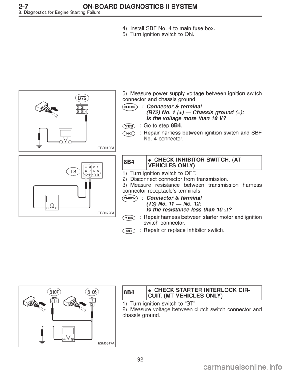
4) Install SBF No. 4 to main fuse box.
5) Turn ignition switch to ON.
OBD0103A
6) Measure power supply voltage between ignition switch
connector and chassis ground.
: Connector & terminal
(B72) No. 1 (+)—Chassis ground (�):
Is the voltage more than 10 V?
: Go to step8B4.
: Repair harness between ignition switch and SBF
No. 4 connector.
OBD0726A
8B4�CHECK INHIBITOR SWITCH. (AT
VEHICLES ONLY)
1) Turn ignition switch to OFF.
2) Disconnect connector from transmission.
3) Measure resistance between transmission harness
connector receptacle’s terminals.
: Connector & terminal
(T3) No. 11—No. 12:
Is the resistance less than 10Ω?
: Repair harness between starter motor and ignition
switch connector.
: Repair or replace inhibitor switch.
B2M0517A
8B4�CHECK STARTER INTERLOCK CIR-
CUIT. (MT VEHICLES ONLY)
1) Turn ignition switch to“ST”.
2) Measure voltage between clutch switch connector and
chassis ground.
92
2-7ON-BOARD DIAGNOSTICS II SYSTEM
8. Diagnostics for Engine Starting Failure
Page 2291 of 2890
B4M0733A
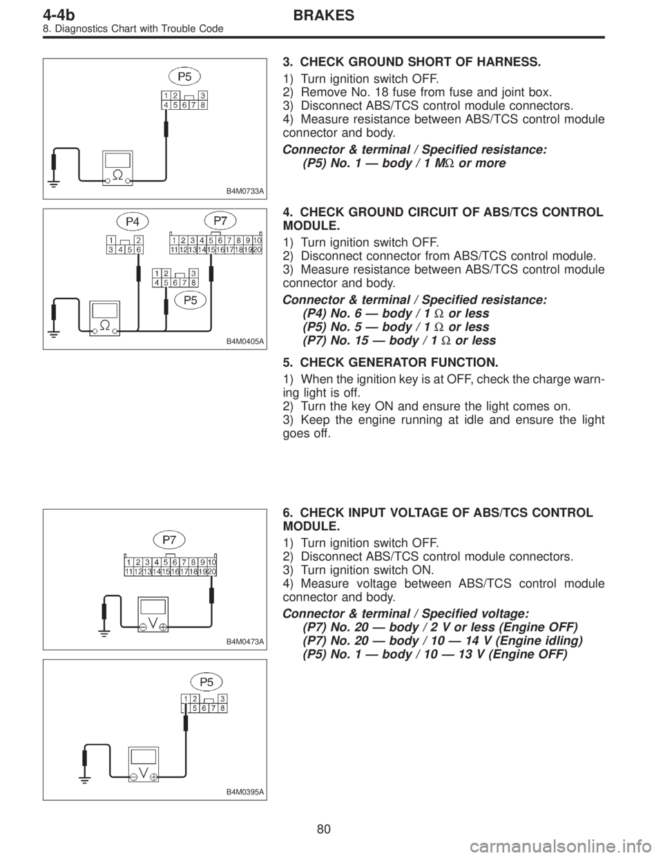
3. CHECK GROUND SHORT OF HARNESS.
1) Turn ignition switch OFF.
2) Remove No. 18 fuse from fuse and joint box.
3) Disconnect ABS/TCS control module connectors.
4) Measure resistance between ABS/TCS control module
connector and body.
Connector & terminal / Specified resistance:
(P5) No. 1—body/1MΩor more
B4M0405A
4. CHECK GROUND CIRCUIT OF ABS/TCS CONTROL
MODULE.
1) Turn ignition switch OFF.
2) Disconnect connector from ABS/TCS control module.
3) Measure resistance between ABS/TCS control module
connector and body.
Connector & terminal / Specified resistance:
(P4) No. 6—body / 1Ωor less
(P5) No. 5—body / 1Ωor less
(P7) No. 15—body / 1Ωor less
5. CHECK GENERATOR FUNCTION.
1) When the ignition key is at OFF, check the charge warn-
ing light is off.
2) Turn the key ON and ensure the light comes on.
3) Keep the engine running at idle and ensure the light
goes off.
B4M0473A
B4M0395A
6. CHECK INPUT VOLTAGE OF ABS/TCS CONTROL
MODULE.
1) Turn ignition switch OFF.
2) Disconnect ABS/TCS control module connectors.
3) Turn ignition switch ON.
4) Measure voltage between ABS/TCS control module
connector and body.
Connector & terminal / Specified voltage:
(P7) No. 20—body/2Vorless (Engine OFF)
(P7) No. 20—body / 10—14 V (Engine idling)
(P5) No. 1—body / 10—13 V (Engine OFF)
80
4-4bBRAKES
8. Diagnostics Chart with Trouble Code
Page 2361 of 2890
B4M0797A
7B5
CHECK GROUND CIRCUIT OF ABSCM.
1) Turn ignition switch to OFF.
2) Measure resistance between ABSCM connector and
chassis ground.
: Connector & terminal
(F49) No. 1—Chassis ground:
(F49) No. 55—Chassis ground:
Is resistance less than 0.5Ω?
: Go to step7B6.
: Repair ABSCM ground harness.
7B6
CHECK WIRING HARNESS.
1) Disconnect connector (F50) from relay box.
2) Turn ignition switch to ON.
: Does the ABS warning light remain off?
: Go to step7B7.
: Repair front wiring harness.
7B7
CHECK RELAY BOX.
1) Turn ignition switch to OFF.
2) Connect connector (F50) to relay box.
3) Remove valve relay from relay box.
4) Disconnect connector (ABS1) from hydraulic control
unit.
5) Turn ignition switch to ON.
: Does the ABS warning light remain off?
: Go to step7B8.
: Repair relay box and check fuse.
21
4-4cBRAKES [ABS 5.3 TYPE]
7. Diagnostics Chart for ABS Warning Light Circuit and Diagnosis Circuit Failure
Page 2419 of 2890
B4M0862B
8K4CHECK POWER SUPPLY VOLTAGE AT
VALVE RELAY CONTACT POINT.
1) Disconnect connector (F8) from relay box.
2) Measure voltage between relay box connector and
chassis ground.
: Connector & terminal
(F8) No. 1 (+)—Chassis ground (�)
Is voltage 10—13 V?
: Go to step8K5.
: Repair harness connector between battery and
relay box. Check fuse No. 19.
B4M0863B
8K5CHECK GROUND CIRCUIT OF RELAY
BOX.
1) Disconnect connector (F50) from relay box.
2) Measure resistance between relay box connector and
chassis ground.
: Connector & terminal
(F50) No. 3—Chassis ground
Is resistance less than 0.5Ω?
: Go to step8K6.
: Repair relay box ground harness.
79
4-4cBRAKES [ABS 5.3 TYPE]
8. Diagnostics Chart with Trouble Code
Page 2420 of 2890
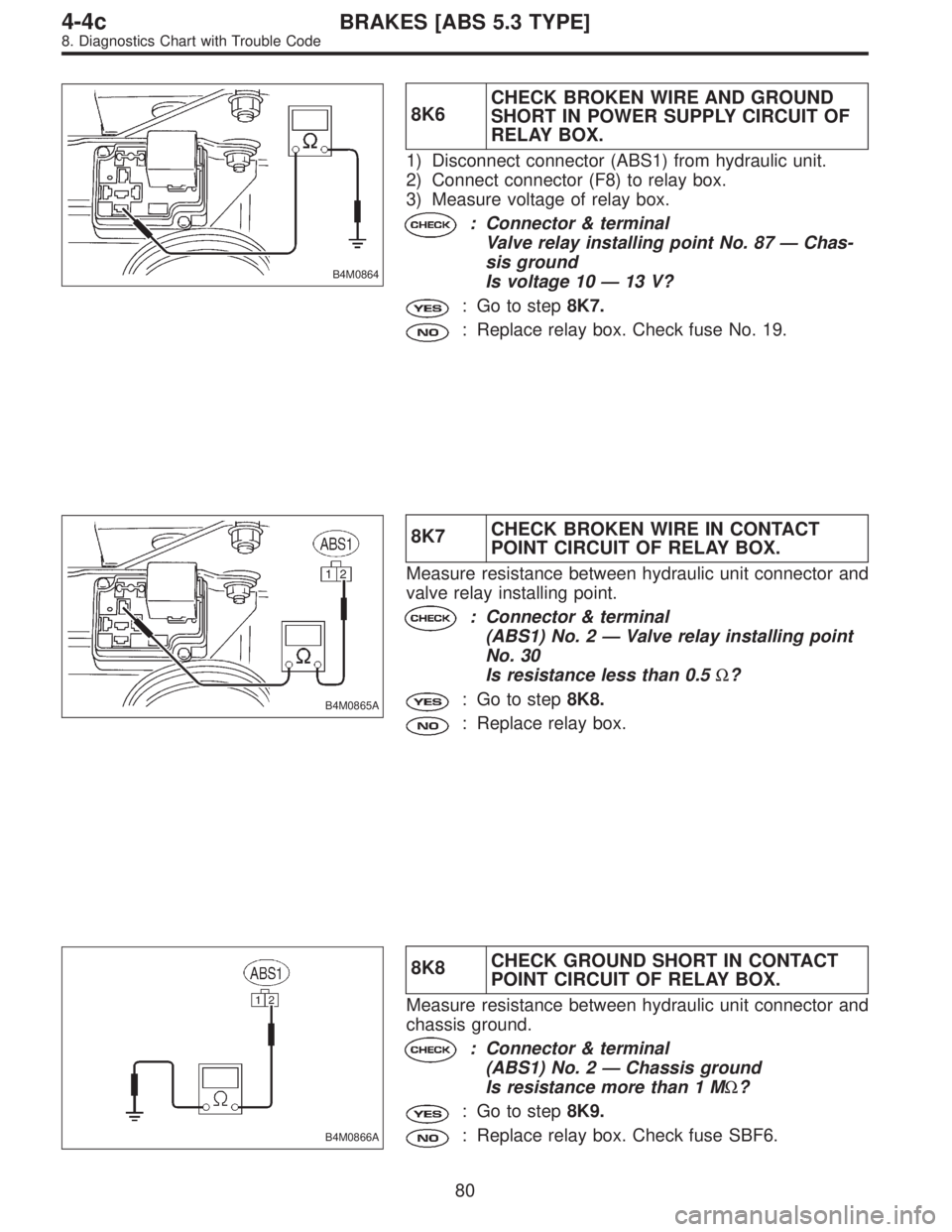
B4M0864
8K6CHECK BROKEN WIRE AND GROUND
SHORT IN POWER SUPPLY CIRCUIT OF
RELAY BOX.
1) Disconnect connector (ABS1) from hydraulic unit.
2) Connect connector (F8) to relay box.
3) Measure voltage of relay box.
: Connector & terminal
Valve relay installing point No. 87—Chas-
sis ground
Is voltage 10—13 V?
: Go to step8K7.
: Replace relay box. Check fuse No. 19.
B4M0865A
8K7CHECK BROKEN WIRE IN CONTACT
POINT CIRCUIT OF RELAY BOX.
Measure resistance between hydraulic unit connector and
valve relay installing point.
: Connector & terminal
(ABS1) No. 2—Valve relay installing point
No. 30
Is resistance less than 0.5Ω?
: Go to step8K8.
: Replace relay box.
B4M0866A
8K8CHECK GROUND SHORT IN CONTACT
POINT CIRCUIT OF RELAY BOX.
Measure resistance between hydraulic unit connector and
chassis ground.
: Connector & terminal
(ABS1) No. 2—Chassis ground
Is resistance more than 1 MΩ?
: Go to step8K9.
: Replace relay box. Check fuse SBF6.
80
4-4cBRAKES [ABS 5.3 TYPE]
8. Diagnostics Chart with Trouble Code