Page 2438 of 2890
B4M0899A
8L14CHECK BROKEN WIRE IN RELAY CON-
TROL SYSTEM HARNESS.
1) Connect valve relay and motor relay to relay box.
2) Connect connector (F50) to relay box.
3) Connect connector to hydraulic unit.
4) Measure resistance between ABSCM connector and
chassis ground.
: Connector & terminal
(F49) No. 22—Chassis ground
Is resistance 80±10Ω?
: Go to step8L15.
: Repair harness connector between ABSCM and
relay box.
B4M0900A
8L15CHECK GROUND SHORT BETWEEN
RELAY BOX AND ABSCM.
1) Disconnect connector (F50) from relay box.
2) Measure resistance between ABSCM connector and
chassis ground.
: Connector & terminal
(F49) No. 22—Chassis ground
(F49) No. 10—Chassis ground
Is resistance more than 1 MΩ?
: Go to step8L16.
: Repair harness between ABSCM and relay box.
Check fuse No. 19 and SBF6.
98
4-4cBRAKES [ABS 5.3 TYPE]
8. Diagnostics Chart with Trouble Code
Page 2439 of 2890
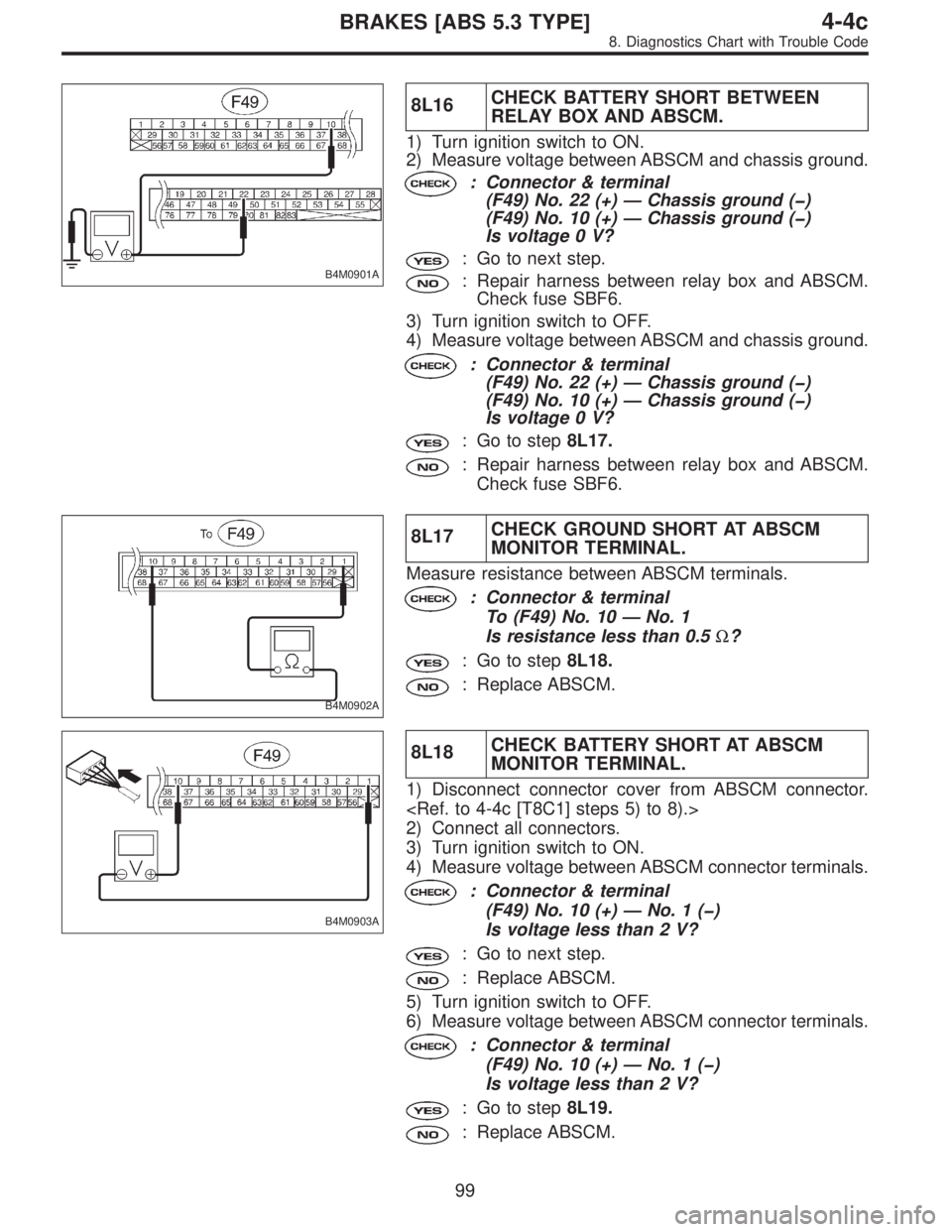
B4M0901A
8L16CHECK BATTERY SHORT BETWEEN
RELAY BOX AND ABSCM.
1) Turn ignition switch to ON.
2) Measure voltage between ABSCM and chassis ground.
: Connector & terminal
(F49) No. 22 (+)—Chassis ground (�)
(F49) No. 10 (+)—Chassis ground (�)
Is voltage 0 V?
: Go to next step.
: Repair harness between relay box and ABSCM.
Check fuse SBF6.
3) Turn ignition switch to OFF.
4) Measure voltage between ABSCM and chassis ground.
: Connector & terminal
(F49) No. 22 (+)—Chassis ground (�)
(F49) No. 10 (+)—Chassis ground (�)
Is voltage 0 V?
: Go to step8L17.
: Repair harness between relay box and ABSCM.
Check fuse SBF6.
B4M0902A
8L17CHECK GROUND SHORT AT ABSCM
MONITOR TERMINAL.
Measure resistance between ABSCM terminals.
: Connector & terminal
To (F49) No. 10—No. 1
Is resistance less than 0.5Ω?
: Go to step8L18.
: Replace ABSCM.
B4M0903A
8L18CHECK BATTERY SHORT AT ABSCM
MONITOR TERMINAL.
1) Disconnect connector cover from ABSCM connector.
2) Connect all connectors.
3) Turn ignition switch to ON.
4) Measure voltage between ABSCM connector terminals.
: Connector & terminal
(F49) No. 10 (+)—No.1(�)
Is voltage less than 2 V?
: Go to next step.
: Replace ABSCM.
5) Turn ignition switch to OFF.
6) Measure voltage between ABSCM connector terminals.
: Connector & terminal
(F49) No. 10 (+)—No.1(�)
Is voltage less than 2 V?
: Go to step8L19.
: Replace ABSCM.
99
4-4cBRAKES [ABS 5.3 TYPE]
8. Diagnostics Chart with Trouble Code
Page 2547 of 2890
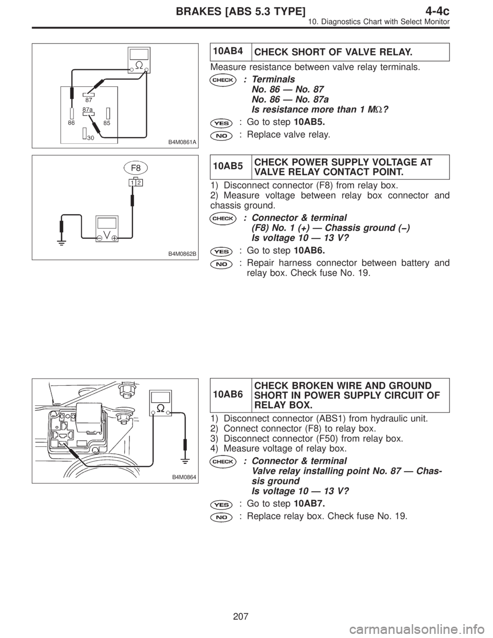
B4M0861A
10AB4
CHECK SHORT OF VALVE RELAY.
Measure resistance between valve relay terminals.
: Terminals
No. 86—No. 87
No. 86—No. 87a
Is resistance more than 1 MΩ?
: Go to step10AB5.
: Replace valve relay.
B4M0862B
10AB5CHECK POWER SUPPLY VOLTAGE AT
VALVE RELAY CONTACT POINT.
1) Disconnect connector (F8) from relay box.
2) Measure voltage between relay box connector and
chassis ground.
: Connector & terminal
(F8) No. 1 (+)—Chassis ground (�)
Is voltage 10—13 V?
: Go to step10AB6.
: Repair harness connector between battery and
relay box. Check fuse No. 19.
B4M0864
10AB6CHECK BROKEN WIRE AND GROUND
SHORT IN POWER SUPPLY CIRCUIT OF
RELAY BOX.
1) Disconnect connector (ABS1) from hydraulic unit.
2) Connect connector (F8) to relay box.
3) Disconnect connector (F50) from relay box.
4) Measure voltage of relay box.
: Connector & terminal
Valve relay installing point No. 87—Chas-
sis ground
Is voltage 10—13 V?
: Go to step10AB7.
: Replace relay box. Check fuse No. 19.
207
4-4cBRAKES [ABS 5.3 TYPE]
10. Diagnostics Chart with Select Monitor
Page 2548 of 2890
B4M0865A
10AB7CHECK BROKEN WIRE IN CONTACT
POINT CIRCUIT OF RELAY BOX.
Measure resistance between hydraulic unit connector and
valve relay installing point.
: Connector & terminal
(ABS1) No. 2—Valve relay installing point
No. 30
Is resistance less than 0.5Ω?
: Go to step10AB8.
: Replace relay box.
B4M0866A
10AB8CHECK GROUND SHORT IN CONTACT
POINT CIRCUIT OF RELAY BOX.
Measure resistance between relay box connector and
chassis ground.
: Connector & terminal
(ABS1) No. 2—Chassis ground
Is resistance more than 1 MΩ?
: Go to step10AB9.
: Replace relay box. Check fuse SBF6.
B4M0868B
10AB9
CHECK DIODE OF RELAY BOX.
Measure resistance between relay box connector and
valve relay installing point.
: Connector & terminal
Valve relay installing point No. 30 (+)—To
(F50) No. 2 (�)
Is resistance more than 1 MΩ?
: Go to step10AB10.
: Replace relay box.
208
4-4cBRAKES [ABS 5.3 TYPE]
10. Diagnostics Chart with Select Monitor
Page 2549 of 2890
B4M0870B
10AB10CHECK BATTERY SHORT IN GROUND
CIRCUIT OF RELAY BOX.
1) Disconnect connector from ABSCM.
2) Turn ignition switch to ON.
3) Measure voltage between relay box connector and
chassis ground.
: Connector & terminal
To (F50) No. 3 (+)—Chassis ground (�)
Is voltage 0 V?
: Go to next step.
: Replace relay box and check all fuses.
4) Turn ignition switch to OFF.
5) Measure voltage between relay box connector and
chassis ground.
: Connector & terminal
To (F50) No. 3 (+)—Chassis ground (�)
Is voltage 0 V?
: Go to step10AB11.
: Replace relay box and check all fuses.
B4M0871B
10AB11CHECK BROKEN WIRE IN CONTROL
CIRCUIT OF RELAY BOX.
1) Install valve relay to relay box.
2) Measure resistance between relay box connector termi-
nals.
: Connector & terminal
To (F50) No. 1—No. 5
Is resistance 103±10Ω?
: Go to step10AB12.
: Replace relay box.
209
4-4cBRAKES [ABS 5.3 TYPE]
10. Diagnostics Chart with Select Monitor
Page 2550 of 2890
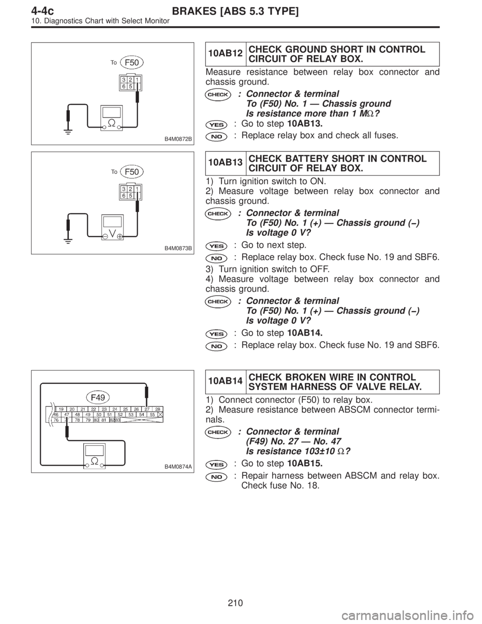
B4M0872B
10AB12CHECK GROUND SHORT IN CONTROL
CIRCUIT OF RELAY BOX.
Measure resistance between relay box connector and
chassis ground.
: Connector & terminal
To (F50) No. 1—Chassis ground
Is resistance more than 1 MΩ?
: Go to step10AB13.
: Replace relay box and check all fuses.
B4M0873B
10AB13CHECK BATTERY SHORT IN CONTROL
CIRCUIT OF RELAY BOX.
1) Turn ignition switch to ON.
2) Measure voltage between relay box connector and
chassis ground.
: Connector & terminal
To (F50) No. 1 (+)—Chassis ground (�)
Is voltage 0 V?
: Go to next step.
: Replace relay box. Check fuse No. 19 and SBF6.
3) Turn ignition switch to OFF.
4) Measure voltage between relay box connector and
chassis ground.
: Connector & terminal
To (F50) No. 1 (+)—Chassis ground (�)
Is voltage 0 V?
: Go to step10AB14.
: Replace relay box. Check fuse No. 19 and SBF6.
B4M0874A
10AB14CHECK BROKEN WIRE IN CONTROL
SYSTEM HARNESS OF VALVE RELAY.
1) Connect connector (F50) to relay box.
2) Measure resistance between ABSCM connector termi-
nals.
: Connector & terminal
(F49) No. 27—No. 47
Is resistance 103±10Ω?
: Go to step10AB15.
: Repair harness between ABSCM and relay box.
Check fuse No. 18.
210
4-4cBRAKES [ABS 5.3 TYPE]
10. Diagnostics Chart with Select Monitor
Page 2551 of 2890
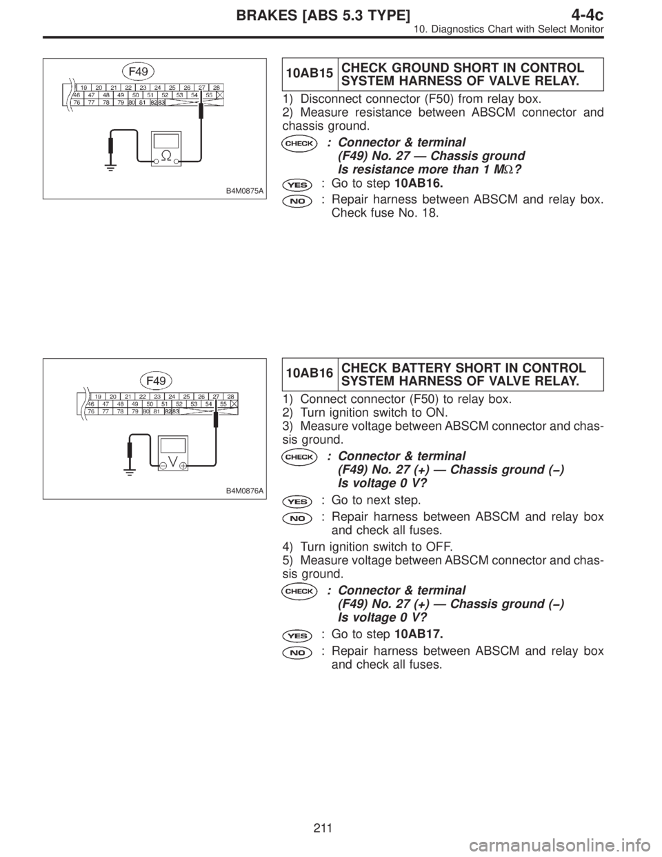
B4M0875A
10AB15CHECK GROUND SHORT IN CONTROL
SYSTEM HARNESS OF VALVE RELAY.
1) Disconnect connector (F50) from relay box.
2) Measure resistance between ABSCM connector and
chassis ground.
: Connector & terminal
(F49) No. 27—Chassis ground
Is resistance more than 1 MΩ?
: Go to step10AB16.
: Repair harness between ABSCM and relay box.
Check fuse No. 18.
B4M0876A
10AB16CHECK BATTERY SHORT IN CONTROL
SYSTEM HARNESS OF VALVE RELAY.
1) Connect connector (F50) to relay box.
2) Turn ignition switch to ON.
3) Measure voltage between ABSCM connector and chas-
sis ground.
: Connector & terminal
(F49) No. 27 (+)—Chassis ground (�)
Is voltage 0 V?
: Go to next step.
: Repair harness between ABSCM and relay box
and check all fuses.
4) Turn ignition switch to OFF.
5) Measure voltage between ABSCM connector and chas-
sis ground.
: Connector & terminal
(F49) No. 27 (+)—Chassis ground (�)
Is voltage 0 V?
: Go to step10AB17.
: Repair harness between ABSCM and relay box
and check all fuses.
211
4-4cBRAKES [ABS 5.3 TYPE]
10. Diagnostics Chart with Select Monitor
Page 2560 of 2890
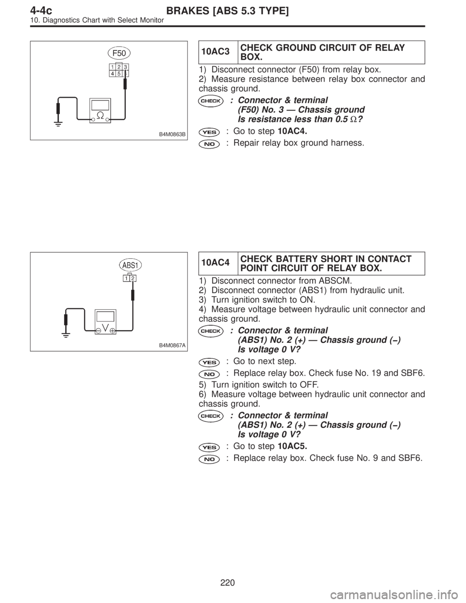
B4M0863B
10AC3CHECK GROUND CIRCUIT OF RELAY
BOX.
1) Disconnect connector (F50) from relay box.
2) Measure resistance between relay box connector and
chassis ground.
: Connector & terminal
(F50) No. 3—Chassis ground
Is resistance less than 0.5Ω?
: Go to step10AC4.
: Repair relay box ground harness.
B4M0867A
10AC4CHECK BATTERY SHORT IN CONTACT
POINT CIRCUIT OF RELAY BOX.
1) Disconnect connector from ABSCM.
2) Disconnect connector (ABS1) from hydraulic unit.
3) Turn ignition switch to ON.
4) Measure voltage between hydraulic unit connector and
chassis ground.
: Connector & terminal
(ABS1) No. 2 (+)—Chassis ground (�)
Is voltage 0 V?
: Go to next step.
: Replace relay box. Check fuse No. 19 and SBF6.
5) Turn ignition switch to OFF.
6) Measure voltage between hydraulic unit connector and
chassis ground.
: Connector & terminal
(ABS1) No. 2 (+)—Chassis ground (�)
Is voltage 0 V?
: Go to step10AC5.
: Replace relay box. Check fuse No. 9 and SBF6.
220
4-4cBRAKES [ABS 5.3 TYPE]
10. Diagnostics Chart with Select Monitor