Page 173 of 2890
![SUBARU LEGACY 1996 Service Repair Manual 6-3
[D601]
WIRING
DIAGRAM
6
.
Wiring
Diagram
6
.
Wiring
Diagram
Batterycurrent
1
.
POWER
SUPPLY
ROUTING
Current
fromignition
switch
IG
terminal
---
Current
fromignition
switch
ACC
terminal
-----](/manual-img/17/57433/w960_57433-172.png "SUBARU LEGACY 1996 Service Repair Manual 6-3
[D601]
WIRING
DIAGRAM
6
.
Wiring
Diagram
6
.
Wiring
Diagram
Batterycurrent
1
.
POWER
SUPPLY
ROUTING
Current
fromignition
switch
IG
terminal
---
Current
fromignition
switch
ACC
terminal
-----")
6-3
[D601]
WIRING
DIAGRAM
6
.
Wiring
Diagram
6
.
Wiring
Diagram
Batterycurrent
1
.
POWER
SUPPLY
ROUTING
Current
fromignition
switch
IG
terminal
---
Current
fromignition
switch
ACC
terminal
-------
Other
currents
Mainfuse
box
(M/B)
g27
SBF-5
45A
~
L
SBF-4
45A
,
BY
r-,
coc_
:
/CA
1
Do
BF-1
30A
BF-2
30A
N
m
m
M/B
FUSE/RELAY
LOCATION
826
-
MB-1
2
Rw
M
B-2
1
MB-3
R
-
MB-4
(
:8
~V
:
9)
,
R
F35
Headlight
No
.
22
15A
5
W
relay
LHNo
.
23
20A
Br
6
°
No
.
24
15A
RL
-----
---------
------0'
~-P--
1
---------°^----
MB-6
7
LB
7
No
.
26
15A
BY
°
~
~
_
No
.
25
15A
3
--°--°
BR
MB-8
.J
4
LR
2
MB-9
Headlight
relay
RH
F38
r~W
WC
relay
holder
mmllmm
O
~
SBFSBF
~~~
~
Head
i~25
N0
'
24
Headlight
4A
No,
relay
RH
~
SBF
~
38fSBf
N0
.
b
F/B
a
N0
.
--
2
:
0
N0
.f
o
N
.
176
N
RU7
.
R-DEF
N0
.
7
N0
.
N
.
3
0N
.
It
.4
~~
P
I
.7
LEI]
o
O
N0
.
19N0
.
12N0
.
~y~~~,~~~
ILLUrtI
.
O
N0.21
N0
.
14
N0
.7
MAIN
FAN
,
D
2
IF--
F26
F38
(B
I
ec
k)
2
B27
123
--'----
ALT-1
B26
(B
I
ac
k)
F26
(Grey)
12
F35
(B
I
ec
k)
1234
5678
BURO1-01A
Page 174 of 2890

BN
CSNo
.
11
20A
e7
No
.
17
15A
\"
--O~-o------------
NO
.
3
20A
----
~")
WIRING
DIAGRAM
[nso1i
6-3
6
.
Wiring
Diagram
mm~
86I
O7
M
F44
m
a
:
F40
b
:
Bill
c
:
F42
Fuse
end
relay
box
(F/B)
BN
CSNo
.
11
20A
e7
No
.
17
15A
"
--O'~-o------------
NO
.
3
20A
----
~
'
--0
~4-----
-t
L
.__
.
.--
..__
.--
~~-~-0-
No-
.
-
2
-
20A
-------1-
FB-2
~R
e4
----------
FB-3
-°-
a3
-
---
--------°-°-°------
Y
-
Sub
fan
re
la
1
0
L
b
1
No
.
13
20A
_
_
No
.
14
l0A
FB-4
B72
U-
o
UaZ
i
o
RY
1
Br
-
-R
2
ACC
U
LR
5
IG-I
ST
Ignition
switch
d
:
BSl
I
e
:
852
I
f
:
i5
IG
e9
w~
__
.
.--
St
FB-7
f4
FB-9
e4
RY
W
e1
Y
FB-10
fll
f5
-
G
-
-----
--
-
-
FB-11
FB-
2
1
fl
R
1
--
-
-
FB-13
e3
-----
FB-14
No
.
OA
°
---°-
efo
er
relay
No
.
1
15A
No
.
15
l0A
_
No
.
8
15A
No
.
16
15A
F
B-37
YR
--
B
15
RL
°---
--------------
FB-16
BL
FB-17
BYBY
FB-18
RB
FB-19
GW
FB-20
RB
FB-21
FB-22
-
GY
FB23
-
BGF824
F
tE
---------------
-
B-25
---
r
iaii&
iiiumination
l~l
relay
,
BrR
~
-
dll
T
FB
27
___
..
.__--___J
~
_
.____
.__-
i
wG
.
.____
.__
._._.
FB-28
.
9
l0A
NoBRNo
.
1
A2
20
d
Gw
-
c2
3
FB30RY
5A
21
No
.
1
d9RY32
FB-
No
.
20
15A
~-°
.O'`
O-No_
5
__
l0A--------------
-7
R_-_-_°-----°--
FB-3FB-6
,
t
e4
R
N
o
.18
l0A
L
BRc3
6
1
SAd4
FB-35
F44872F40
Blll
F42
851
B52
i5
(B
I
ack)
(Gray)
(Gray)(Gray)(Gray)(Gray)(Gray)
1
2
34
123
5678
456
1
23
45
6789
0
213
342
678910151
ffm~i~
2131
7
7891
1112
891
11
1
1415
BUR01-018
3
Page 505 of 2890

CONDITION:
�Engine coolant temperature is above 95°C (203°F).
TROUBLE SYMPTOM:
�Radiator main fan does not operate under the above
condition.
1. Check fuse and power")
A: OPERATION (WITHOUT A/C MODEL)
CONDITION:
�Engine coolant temperature is above 95°C (203°F).
TROUBLE SYMPTOM:
�Radiator main fan does not operate under the above
condition.
1. Check fuse and power supply.
OK
�Not OK
Melted fuse,repair the shorted part of the circuit
,replace fuse.
2. Check harness connector between fuse and
relay box, and A/C relay holder.
OK
�Not OK
Repair or replace wiring harness.
3. Check A/C relay holder.
OK
�Not OK
Repair or replace A/C relay holder.
4. Check harness connector between A/C relay
holder and main fan motor.
OK
�Not OK
Repair or replace wiring harness.
5. Check ground circuit of main fan motor.
OK
�Not OK
Repair or replace wiring harness.
6. Check main fan motor.
OK
�Not OK
Replace main fan motor.
Refer to 2-7 On-Board Diagnostics II System.
B2M0427A
1. CHECK FUSE AND POWER SUPPLY.
1) Check fuse No. 13.
2) Turn ignition switch to ACC.
3) Measure voltage between fuse and relay box, and body.
Connector & terminal / Specified voltage:
(F40) No. 3—Body / 10 V, or more
�
�
�
�
�
�
22
2-5DIAGNOSTICS
2. Radiator Main Fan
Page 506 of 2890
 Turn ignition switch to OFF.
2) Disconnect connectors from fuse and relay box, and
A/C relay holder.
3) Measure")
B2M0325A
2. CHECK HARNESS CONNECTOR BETWEEN FUSE
AND RELAY BOX, AND A/C RELAY HOLDER.
1) Turn ignition switch to OFF.
2) Disconnect connectors from fuse and relay box, and
A/C relay holder.
3) Measure resistance of harness connector between fuse
and relay box, and A/C relay holder.
Connector & terminal / Specified resistance:
(F40) No. 3—(F29) No. 2 / 10Ω, max.
B2M0428A
3. CHECK A/C RELAY HOLDER.
1) Disconnect connector from A/C relay holder.
2) Measure resistance between terminals of A/C relay
holder.
Connector & terminal / Specified resistance:
(F29) No. 2—(F28) No. 4 / 10Ω, max.
(F29) No. 2—(F30) No. 4 / 10Ω, max.
B2M0366A
4. CHECK HARNESS CONNECTOR BETWEEN A/C
RELAY HOLDER AND MAIN FAN MOTOR.
1) Disconnect connectors from A/C relay holder and main
fan motor.
2) Measure resistance of harness connector between A/C
relay holder and main fan motor.
Connector & terminal / Specified resistance:
(F28) No. 4—(F17) No. 2 / 10Ω, max.
(F30) No. 4—(F17) No. 3 / 10Ω, max.
B2M0367A
5. CHECK GROUND CIRCUIT OF MAIN FAN MOTOR.
Measure resistance between main fan motor connector
and body.
Connector & terminal / Specified resistance:
(F17) No. 1—Body / 10Ω, max.
B2M0368A
6. CHECK MAIN FAN MOTOR.
1) Disconnect connector from main fan motor.
2) Connect battery positive (+) terminal to terminals No. 2
and No. 3, and connect terminal No. 1 to ground. Ensure
that fan rotates.
23
2-5DIAGNOSTICS
2. Radiator Main Fan
Page 514 of 2890
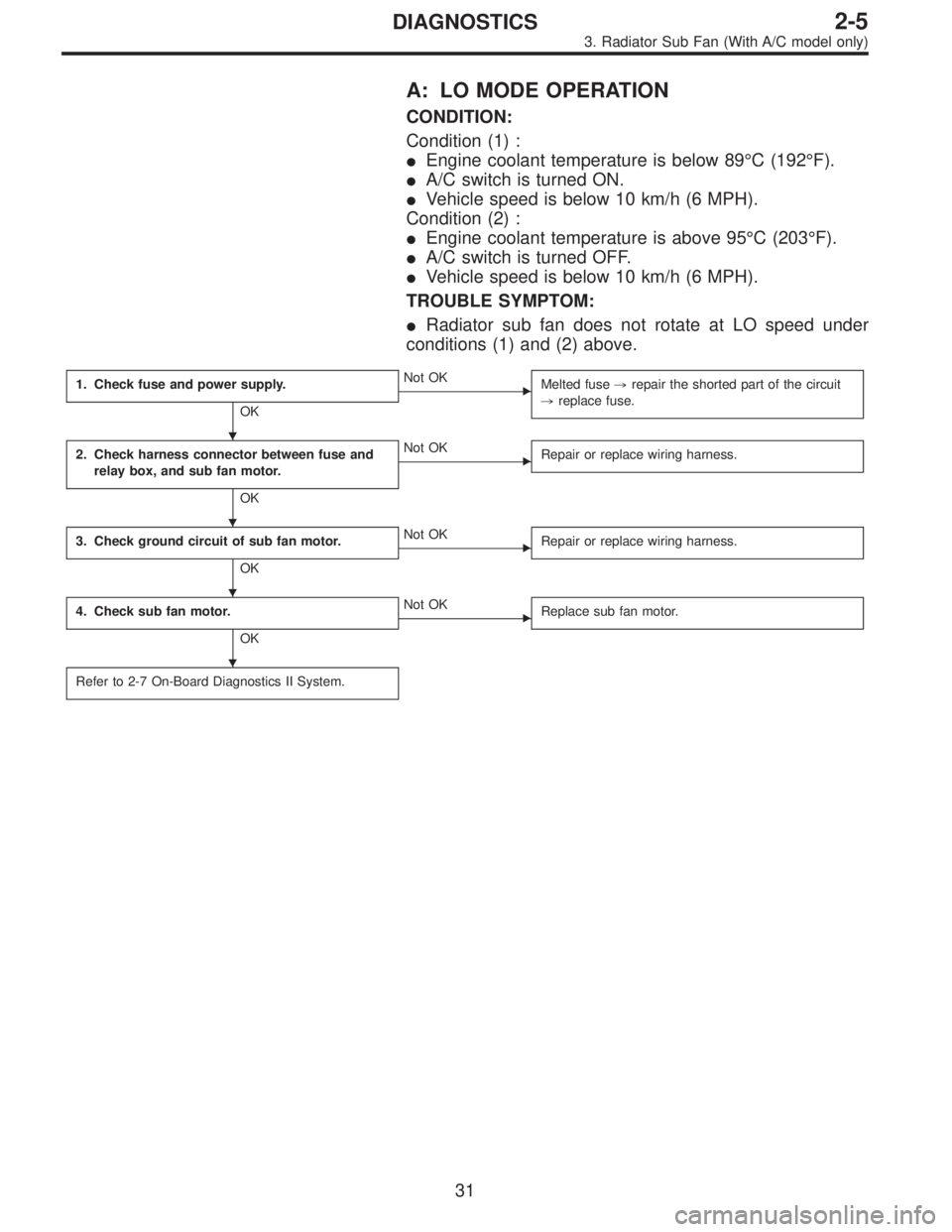
A: LO MODE OPERATION
CONDITION:
Condition (1) :
�Engine coolant temperature is below 89°C (192°F).
�A/C switch is turned ON.
�Vehicle speed is below 10 km/h (6 MPH).
Condition (2) :
�Engine coolant temperature is above 95°C (203°F).
�A/C switch is turned OFF.
�Vehicle speed is below 10 km/h (6 MPH).
TROUBLE SYMPTOM:
�Radiator sub fan does not rotate at LO speed under
conditions (1) and (2) above.
1. Check fuse and power supply.
OK
�Not OK
Melted fuse,repair the shorted part of the circuit
,replace fuse.
2. Check harness connector between fuse and
relay box, and sub fan motor.
OK
�Not OK
Repair or replace wiring harness.
3. Check ground circuit of sub fan motor.
OK
�Not OK
Repair or replace wiring harness.
4. Check sub fan motor.
OK
�Not OK
Replace sub fan motor.
Refer to 2-7 On-Board Diagnostics II System.
�
�
�
�
31
2-5DIAGNOSTICS
3. Radiator Sub Fan (With A/C model only)
Page 515 of 2890
 Check fuse No. 13.
2) Turn ignition switch to ACC.
3) Measure voltage between fuse and relay box, and body.
Connector & terminal / Specified voltage:
(F40)")
B2M0427A
1. CHECK FUSE AND POWER SUPPLY.
1) Check fuse No. 13.
2) Turn ignition switch to ACC.
3) Measure voltage between fuse and relay box, and body.
Connector & terminal / Specified voltage:
(F40) No. 3—Body / 10 V, or more
B2M0377A
2. CHECK HARNESS CONNECTOR BETWEEN FUSE
AND RELAY BOX, AND SUB FAN MOTOR.
1) Turn ignition switch to OFF.
2) Disconnect connectors from fuse and relay box, and
sub fan motor.
3) Measure resistance of harness connector between fuse
and relay box, and sub fan motor.
Connector & terminal / Specified resistance:
(F40) No. 3—(F16) No. 2 / 10Ω, max.
B2M0378A
3. CHECK GROUND CIRCUIT OF SUB FAN MOTOR.
Measure resistance between sub fan motor connector and
body.
Connector & terminal / Specified resistance:
(F16) No. 1—Body / 10Ω, max.
B2M0372A
4. CHECK SUB FAN MOTOR.
1) Disconnect connector from sub fan motor.
2) Connect battery positive (+) terminal to terminal No. 2
and connect terminal No. 1 to ground. Ensure that fan
rotates at LO speed.
32
2-5DIAGNOSTICS
3. Radiator Sub Fan (With A/C model only)
Page 548 of 2890
G6M0095
16. Main Relay
A: REMOVAL AND INSTALLATION
1) Disconnect battery ground cable.
B5M0024A
2) Remove lower cover and then disconnect connectors.
3) Lower transmission control module.
4) Remove the front pillar lower trim.
5) Remove fuse box mounting nuts.
6) Lower fuse box.
7) Remove fuse box mounting bracket.
G2M0438
8) Remove screw which retains bracket of main relay�1
and fuel pump relay�2.
9) Disconnect connector from main relay.
G2M0438
10) Installation is in the reverse order of removal.
�
1Main relay
�
2Fuel pump relay
30
2-7SERVICE PROCEDURE
16. Main Relay
Page 549 of 2890
G6M0095
17. Fuel Pump Relay
A: REMOVAL AND INSTALLATION
1) Disconnect battery ground cable.
B5M0024A
2) Remove lower cover and then disconnect connectors.
3) Lower transmission control module.
4) Remove the front pillar lower trim.
5) Remove fuse box mounting nuts.
6) Lower fuse box.
7) Remove fuse box mounting bracket.
G2M0438
8) Remove fuel pump relay from main relay and fuel pump
relay mounting bracket.
9) Disconnect connector from fuel pump relay.
G2M0438
10) Installation is in the reverse order of removal.
�
1Main relay
�
2Fuel pump relay
31
2-7SERVICE PROCEDURE
17. Fuel Pump Relay
 Disconnect battery ground cable.
B5M0024A
2) Remove lower cover and then disconnect connectors.
3) Lower transmission control module.
4) Remove th")
 Disconnect battery ground cable.
B5M0024A
2) Remove lower cover and then disconnect connectors.
3) Lower transmission control module.
4) Remo")