Page 703 of 2890
 Check the routing of clutch cable for smoothness.
2) Excessive tightnes")
1. General
A: PRECAUTION
When servicing clutch system, pay attention to the follow-
ing items.
1. MECHANICAL APPLICATION TYPE
1) Check the routing of clutch cable for smoothness.
2) Excessive tightness or looseness of clutch cable have
a bad influence upon the cable durability.
3) Apply grease sufficiently to the connecting portion of
clutch pedal.
4) Apply grease sufficiently to the release lever portion.
5) Position clutch cable through the center of toe board
hole and route it smoothly. Adjustment is done by moving
the outer cable.
6) Make sure not to let the clutch chatter when starting
forward or rearward. If clutch chattering occurs, readjust so
that the bend of clutch outer cable becomes flatter.
G2M0234
2. On-Car Service
1. MECHANICAL APPLICATION TYPE
1) Remove release lever return spring from lever (Models
without hill holder only).
2) Adjust spherical nut so that the play is within the speci-
fied value at the lever end (center of spherical nut).
CAUTION:
Take care not to twist the cable during adjustment
Play: 3 — 4 mm (0.12 — 0.16 in)
Full stroke: 24 — 26 mm (0.94 — 1.02 in)
G2M0235
3) Upon completion of adjustment, securely lock spherical
nut with lock nut.
Install return spring on lever (Models without hill holder
only).
NOTE:
Hook the long hook side of the return spring with the lever
(Models without hill holder only).
4
2-10SERVICE PROCEDURE
1. General - 2. On-Car Service
Page 760 of 2890

5. SHIFTER FORK AND ROD
Select suitable shifter forks so that both coupling sleeve and
reverse driven gear are positioned in the center of their synchro-
mesh mechanisms.
1st-2nd shifter fork
Part No. Mark Remarks
32804AA060 1Approach to 1st gear by
0.2 mm (0.008 in)
32804AA070 No mark Standard
32804AA080 3Approach to 2nd gear by
0.2 mm (0.008 in)
3rd-4th shifter fork
Part No. Mark Remarks
32810AA060 1Approach to 4th gear by
0.2 mm (0.008 in)
32810AA070 No mark Standard
32810AA100 3Approach to 3rd gear by
0.2 mm (0.008 in)
5th shifter fork
Part No. Mark Remarks
32812AA200 4Approach to 5th gear by
0.2 mm (0.008 in)
32812AA210 No mark Standard
32812AA220 6Become distant from 5th
gear by 0.2 mm (0.008 in)
Rod end clearance
A: 1st-2nd—3rd-4th
0.5—1.5 mm (0.020—0.059 in)
B: 3rd-4th—5th
0.6—1.4 mm (0.024—0.055 in)
6. TRANSMISSION CASE ASSEMBLY
Drive pinion shim adjustment
Drive pinion shim
Part No.Thickness
mm (in)Part No.Thickness
mm (in)
32295AA0310.150
(0.0059)32295AA0710.250
(0.0098)
32295AA0410.175
(0.0069)32295AA0810.275
(0.0108)
32295AA0510.200
(0.0079)32295AA0910.300
(0.0118)
32295AA0610.225
(0.0089)32295AA1010.500
(0.0197)
Hypoid gear backlash
0.13—0.18 mm (0.0051—0.0071 in)Selection of main shaft rear plate
Main shaft rear plate
Dimension“A”mm (in) Part No. Mark
4.00—4.13 (0.1575—0.1626) 32294AA040 1
3.87—3.99 (0.1524—0.1571) 32294AA050 2
7. DRIVE PINION ASSEMBLY
Preload adjustment of thrust bearing
Starting torque
0.3—0.8 N⋅m(3—8 kg-cm, 2.6—6.9 in-lb)
Adjusting washer No. 1
Part No. Thickness mm (in)
803025051 3.925 (0.1545)
803025052 3.950 (0.1555)
803025053 3.975 (0.1565)
803025054 4.000 (0.1575)
803025055 4.025 (0.1585)
803025056 4.050 (0.1594)
803025057 4.075 (0.1604)
Adjusting washer No. 2
Part No. Thickness mm (in)
803025059 3.850 (0.1516)
803025054 4.000 (0.1575)
803025058 4.150 (0.1634)
Assemble a driven shaft and 1st driven gear that are selected for
the proper radial clearance adjustment.
Driven shaft 1st driven gear
Part No.Diameter A
mm (in)Part No.
32229AA13049.959—49.966
(1.9669—
1.9672)32231AA270
32229AA12049.967—49.975
(1.9672—
1.9675)32231AA260
8. DRIVE PINION ASSEMBLY (FWD Model)
Selection of 1st driven gear:
1st driven gear
Outer diameter of bushing mm (in) Part No.
41.983—41.996 (1.6529—1.6534) 32231AA320
41.968—41.982 (1.6523—1.6528) 32231AA330
41.954—41.967 (1.6517—1.6522) 32231AA340
4
3-1SPECIFICATIONS AND SERVICE DATA
1. Manual Transmission and Differential
Page 867 of 2890

C: LINE PRESSURE TEST
1. GENERAL
If the clutch or the brake band shows a sign of slippage or
shifting sensation is not correct, the line pressure should be
checked.
�Excessive shocks during upshifting or shifting takes
place at a higher point than under normal circumstances,
may be due to the line pressure being too high.
�Slippage or inability to operate the vehicle may, in most
cases, be due to loss of oil pressure for the operation of
the clutch, brake band or control valve.
G3M0869
1) Line pressure measurement (under no load)
CAUTION:
�Before measuring line pressure, jack-up front
wheels (front-wheel-drive model) or all wheels (4-wheel
drive model).
�Maintain temperature of ATF at approximately 50°C
(122°F) during measurement.
(ATF will reach the above temperature after idling the
engine for approximately 30 minutes with select lever
in“N”or“P”.)
G3M0869
2) Line pressure measurement (under heavy load)
CAUTION:
�Before measuring line pressure, apply both foot and
parking brakes with all wheels chocked (Same as for
“stall”test conditions).
�Measure line pressure when select lever is in“R”,
“2”with engine under stall conditions.
�Measure line pressure within 5 seconds after shift-
ing the select lever to each position. (If line pressure
needs to be measured again, allow the engine to idle
and then stop. Wait for at least one minute before mea-
surement.)
�Maintain the temperature of ATF at approximately
50°C (122°F) during measurement. (ATF will reach the
above temperature after idling the engine for approxi-
mately 30 minutes with the select lever in“N”or“P”.)
41
3-2SERVICE PROCEDURE
3. Performance Test
Page 1109 of 2890
 17 (0.67)
Turning angleInner tire & wheel 37.6°34.4°
Outer tire & wheel 32.6°30.2°
Steering shaftClearance betwe")
B: SERVICE DATA
Except OUTBACK model OUTBACK model
Steering wheel Free play mm (in) 17 (0.67)
Turning angleInner tire & wheel 37.6°34.4°
Outer tire & wheel 32.6°30.2°
Steering shaftClearance between steering
wheel and column cover
mm (in)3.0 (0.118)
Steering gearbox
(Power steering system)Sliding resistance N (kg, lb) 240.3 (24.5, 54.0) or less
Rack shaft play in radial direc-
tion
mm (in)0.15 (0.0059) or less
Right-turn steering Horizontal movement: 0.3 (0.012) or less
Left-turn steering Vertical movement: 0.15 (0.0059) or less
Input shaft play mm (in)
In radial direction 0.18 (0.0071) or less
In axial direction 0.1 (0.004) or less
Turning resistance N (kg, lb)Within 30 mm (1.18 in) from rack center in straight ahead posi-
tion: Less than 11.18 (1.14, 2.51)
Maximum allowable value: 12.7 (1.3, 2.9)
Oil pump
(Power steering system)Pulley shaft mm (in)
Radial play 0.4 (0.016) or less
Axial play 0.9 (0.035) or less
Pulley
Ditch deflection mm (in)
Resistance to rotation
N (kg, lb)1.0 (0.039) or less
9.22 (0.94, 2.07) or less
Regular pressure
kPa (kg/cm
2, psi)981 (10, 142) or less
Relief pressure
kPa (kg/cm
2, psi)7,355 (75, 1,067)
Steering wheel effort
(Power steering system)At standstill with engine
idling on a concrete road
N (kg, lb)31.4 (3.2, 7.1) or less
At standstill with engine
stalled on a concrete road
N (kg, lb)147 (15, 33) or less
C: RECOMMENDED POWER STEERING
FLUID
Recommended power steering fluid Manufacturer
ATF DEXRON II, ATF DEXRON IIE or ATF
DEXRON IIIB.P.
CALTEX
CASTROL
MOBIL
SHELL
TEXACO
3
4-3SPECIFICATIONS AND SERVICE DATA
1. Steering System
Page 1124 of 2890
G4M0101
9) Disconnect pipes C and D from pipe of gearbox.
CAUTION:
Be careful not to damage these pipes.
NOTE:
Disconnect upper pipe D first, and lower pipe C second.
G4M0102
10) Remove clamp bolts securing gearbox to
crossmember, and remove gearbox.
B4M0132A
B: DISASSEMBLY
1) Disconnect four pipes from gearbox.
2) Secure gearbox removed from vehicle in vice using ST.
ST 926200000 STAND
CAUTION:
Secure the gearbox in a vice using the ST as shown.
Do not attempt to secure it without this ST.
3) Remove tie-rod end and lock nut from gearbox.
G4M0104
4) Remove small clip from boot using pliers, and move
boot to tie-rod end side.
G4M0105
5) Remove boot together with large clips.
17
4-3SERVICE PROCEDURE
3. Steering Gearbox (Power Steering System) [LHD model]
Page 1132 of 2890
 If tie-rod end was removed, screw in lock nut and tie-
rod end to screwed portion of tie-rod, and tighten lock nut
temporarily in a position as shown in figure.
Installed tie-rod length: L")
G4M0126
14) If tie-rod end was removed, screw in lock nut and tie-
rod end to screwed portion of tie-rod, and tighten lock nut
temporarily in a position as shown in figure.
Installed tie-rod length: L
15 mm (0.59 in)
NOTE:
Pay attention to difference between right and left tie-rod
ends.
G4M0127
15) Inspect gearbox as follows:
A. Holding tie-rod end, repeat lock to lock two or three
times as quickly as possible.
B. Holding tie-rod end, turn it slowly at a radius one or two
times as large as possible.
After all, make sure that boot is installed in the specified
position without deflation.
16) Remove gearbox from ST.
ST 926200000 STAND
17) Install four pipes on gearbox.
(1) Connect pipes A and B to four pipe joints of gear-
box. Connect upper pipe B first, and lower pipe A.
Tightening torque:
13±3 N⋅m (1.3±0.3 kg-m, 9.4±2.2 ft-lb)
G4M0101
(2) Connect pipes C and D to gearbox.
Connect lower pipe C first, and upper pipe D second.
Tightening torque:
15±5 N⋅m (1.5±0.5 kg-m, 10.8±3.6 ft-lb)
G4M0102
E: INSTALLATION
1) Insert gearbox into crossmember, being careful not to
damage gearbox boot.
2) Tighten gearbox to crossmember bracket via clamp with
bolt to the specified torque.
Tightening torque:
59±12 N⋅m (6.0±1.2 kg-m, 43±9 ft-lb)
25
4-3SERVICE PROCEDURE
3. Steering Gearbox (Power Steering System) [LHD model]
Page 1164 of 2890
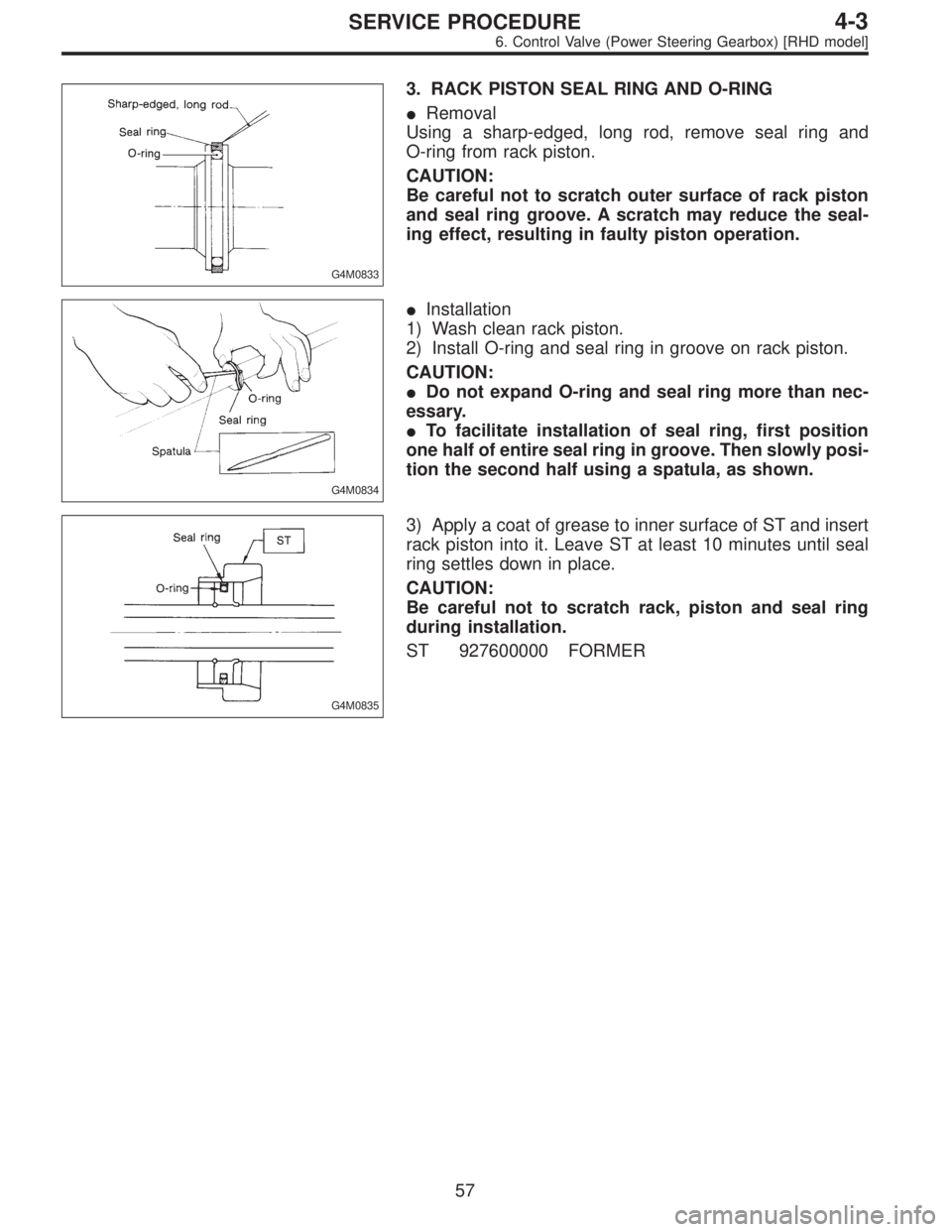
G4M0833
3. RACK PISTON SEAL RING AND O-RING
�Removal
Using a sharp-edged, long rod, remove seal ring and
O-ring from rack piston.
CAUTION:
Be careful not to scratch outer surface of rack piston
and seal ring groove. A scratch may reduce the seal-
ing effect, resulting in faulty piston operation.
G4M0834
�Installation
1) Wash clean rack piston.
2) Install O-ring and seal ring in groove on rack piston.
CAUTION:
�Do not expand O-ring and seal ring more than nec-
essary.
�To facilitate installation of seal ring, first position
one half of entire seal ring in groove. Then slowly posi-
tion the second half using a spatula, as shown.
G4M0835
3) Apply a coat of grease to inner surface of ST and insert
rack piston into it. Leave ST at least 10 minutes until seal
ring settles down in place.
CAUTION:
Be careful not to scratch rack, piston and seal ring
during installation.
ST 927600000 FORMER
57
4-3SERVICE PROCEDURE
6. Control Valve (Power Steering Gearbox) [RHD model]
Page 1172 of 2890
B4M0557A
4) Temporarily install clamp E on pipes C and D.
CAUTION:
Ensure that the letter“8”on each clamp side are
diagonally opposite each other as shown in the figure.
5) Tighten clamp E firmly.
Tightening torque:
7.4±2.0 N⋅m (0.75±0.20 kg-m, 5.4±1.4 ft-lb)
6) Tighten joint nut.
Tightening torque:
15±5 N⋅m (1.5±0.5 kg-m, 10.8±3.6 ft-lb)
G4M0099
7) Connect pipes A and B to four pipe joints of gearbox.
Connect upper pipe B first, and lower pipe A second.
Tightening torque:
13±3 N⋅m (1.3±0.3 kg-m, 9.4±2.2 ft-lb)
8) Install jack-up plate.
9) Connect battery minus terminal.
10) Feed the specified fluid and discharge air.
NOTE:
Never start the engine before feeding the fluid; otherwise
vane pump might be seized up.
65
4-3SERVICE PROCEDURE
7. Pipe Assembly (Power Steering System) [LHD model]
 Disconnect pipes C and D from pipe of gearbox.
CAUTION:
Be careful not to damage these pipes.
NOTE:
Disconnect upper pipe D first, and lower pipe C second.
G4M0102
10) Remove clamp bolts se")
 Temporarily install clamp E on pipes C and D.
CAUTION:
Ensure that the letter“8”on each clamp side are
diagonally opposite each other as shown in the figure.
5) Tighten clamp E firmly.")