Page 1088 of 2890
2. FWD MODEL
Use specified grease.
UFJ side:
UFJ (Front)—NTG2218 (Part No. 28093AA020)
DOJ side:
AT model (Front)—VU-3A702 (Yellow) (Part No.
23223GA050)
MT model (Front)—Molylex No. 2 (Part No.
723223010) or Sunlight TB2-A
1) Place UFJ boot and small boot band on UFJ side of
shaft.
CAUTION:
Be sure to wrap shaft splines with vinyl tape to prevent
boot from scratches.
2) Place drive shaft in a vise.
CAUTION:
Do not place drive shaft directly in the vise; use
wooden blocks.
3) Apply a coat of specified grease [60 to 70 g (2.12 to
2.47 oz)] to UFJ.
4) Apply an even coat of specified grease [20 to 30 g (0.71
to 1.06 oz)] to the entire inner surface of boot. Also apply
grease to shaft.
NOTE:
The inside of the larger end of UFJ boot and the boot
groove shall be cleaned so as to be free from grease and
other substances.
B4M0691A
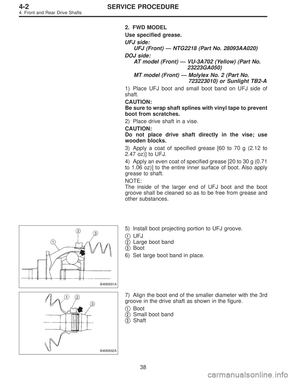
5) Install boot projecting portion to UFJ groove.
�
1UFJ
�
2Large boot band
�
3Boot
6) Set large boot band in place.
B4M0692A
7) Align the boot end of the smaller diameter with the 3rd
groove in the drive shaft as shown in the figure.
�
1Boot
�
2Small boot band
�
3Shaft
38
4-2SERVICE PROCEDURE
4. Front and Rear Drive Shafts
Page 1534 of 2890
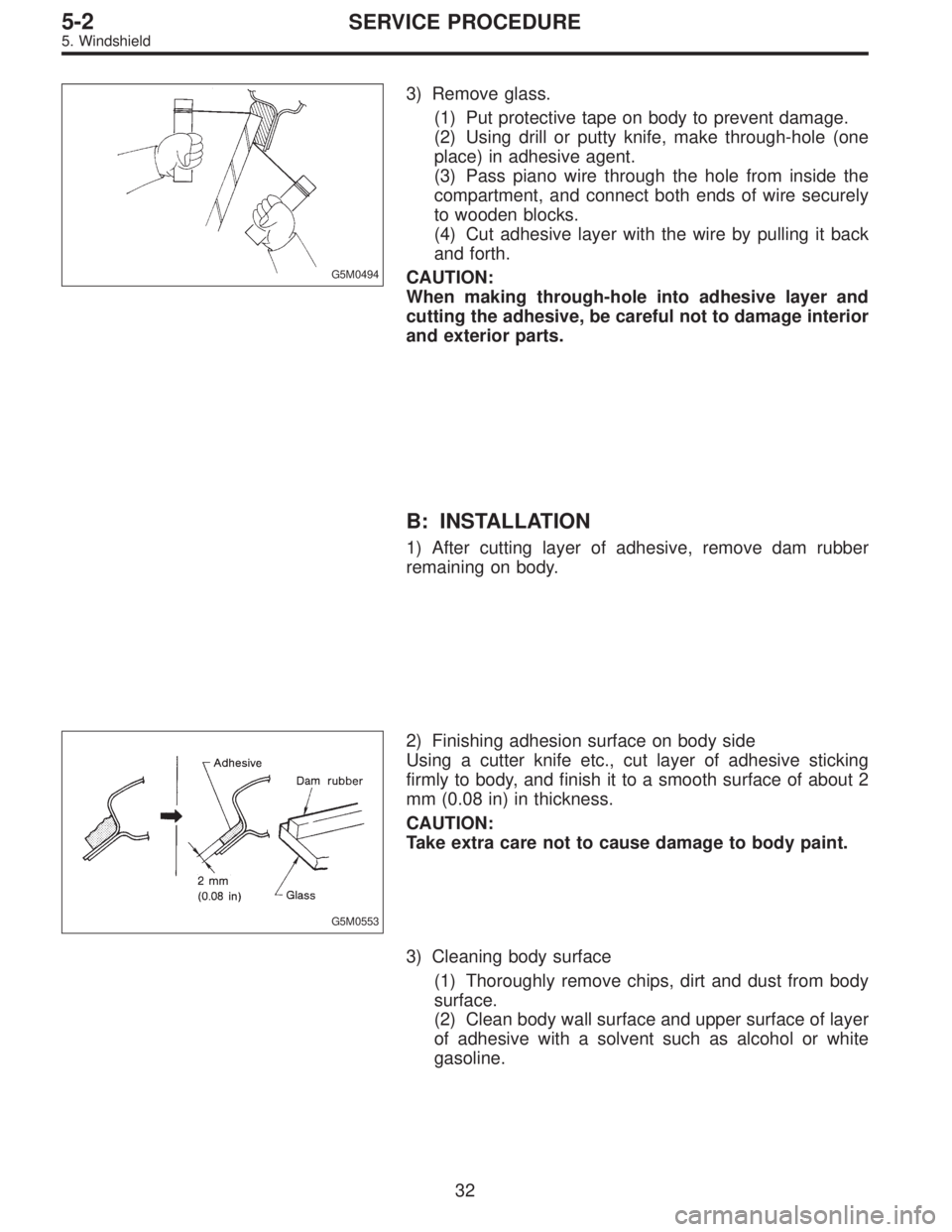
G5M0494
3) Remove glass.
(1) Put protective tape on body to prevent damage.
(2) Using drill or putty knife, make through-hole (one
place) in adhesive agent.
(3) Pass piano wire through the hole from inside the
compartment, and connect both ends of wire securely
to wooden blocks.
(4) Cut adhesive layer with the wire by pulling it back
and forth.
CAUTION:
When making through-hole into adhesive layer and
cutting the adhesive, be careful not to damage interior
and exterior parts.
B: INSTALLATION
1) After cutting layer of adhesive, remove dam rubber
remaining on body.
G5M0553
2) Finishing adhesion surface on body side
Using a cutter knife etc., cut layer of adhesive sticking
firmly to body, and finish it to a smooth surface of about 2
mm (0.08 in) in thickness.
CAUTION:
Take extra care not to cause damage to body paint.
3) Cleaning body surface
(1) Thoroughly remove chips, dirt and dust from body
surface.
(2) Clean body wall surface and upper surface of layer
of adhesive with a solvent such as alcohol or white
gasoline.
32
5-2SERVICE PROCEDURE
5. Windshield
Page 1826 of 2890
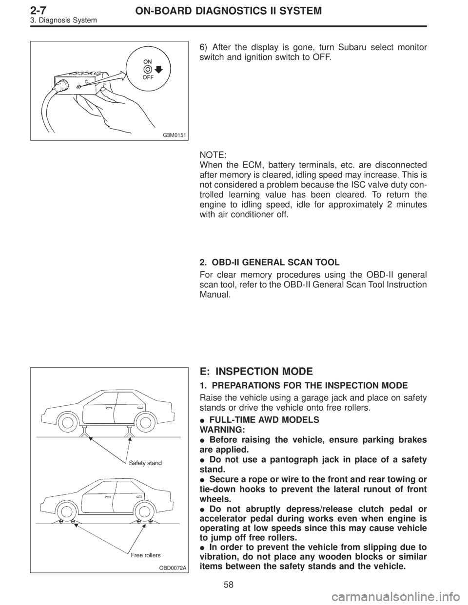
G3M0151
6) After the display is gone, turn Subaru select monitor
switch and ignition switch to OFF.
NOTE:
When the ECM, battery terminals, etc. are disconnected
after memory is cleared, idling speed may increase. This is
not considered a problem because the ISC valve duty con-
trolled learning value has been cleared. To return the
engine to idling speed, idle for approximately 2 minutes
with air conditioner off.
2. OBD-II GENERAL SCAN TOOL
For clear memory procedures using the OBD-II general
scan tool, refer to the OBD-II General Scan Tool Instruction
Manual.
OBD0072A
E: INSPECTION MODE
1. PREPARATIONS FOR THE INSPECTION MODE
Raise the vehicle using a garage jack and place on safety
stands or drive the vehicle onto free rollers.
�FULL-TIME AWD MODELS
WARNING:
�Before raising the vehicle, ensure parking brakes
are applied.
�Do not use a pantograph jack in place of a safety
stand.
�Secure a rope or wire to the front and rear towing or
tie-down hooks to prevent the lateral runout of front
wheels.
�Do not abruptly depress/release clutch pedal or
accelerator pedal during works even when engine is
operating at low speeds since this may cause vehicle
to jump off free rollers.
�In order to prevent the vehicle from slipping due to
vibration, do not place any wooden blocks or similar
items between the safety stands and the vehicle.
58
2-7ON-BOARD DIAGNOSTICS II SYSTEM
3. Diagnosis System
Page 1827 of 2890
�Since the rear wheels will also rotate, do not place
anything near them. Also, make sure that nobody goes
in front of the vehicle.
OBD0073A
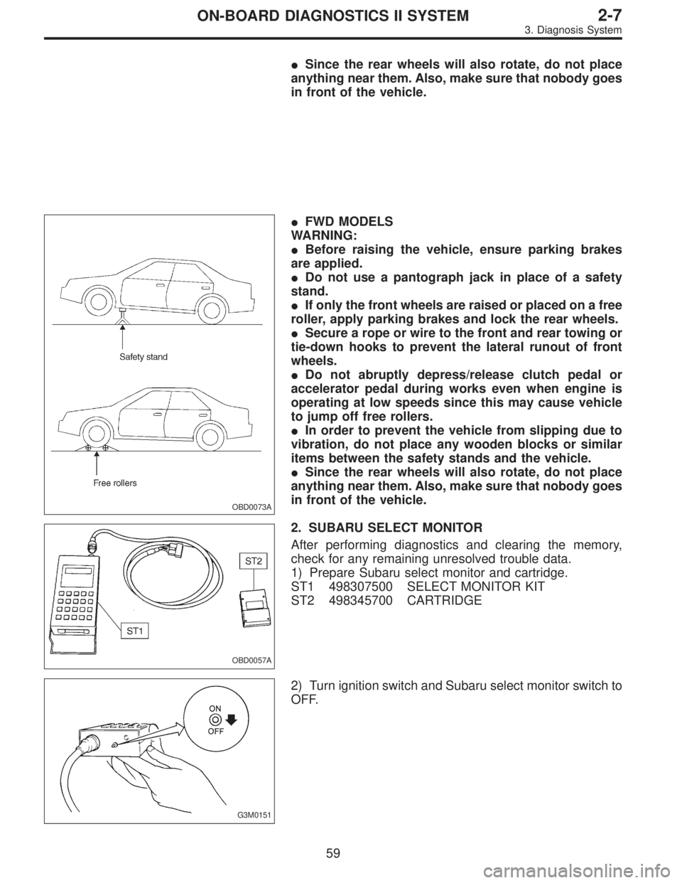
�FWD MODELS
WARNING:
�Before raising the vehicle, ensure parking brakes
are applied.
�Do not use a pantograph jack in place of a safety
stand.
�If only the front wheels are raised or placed on a free
roller, apply parking brakes and lock the rear wheels.
�Secure a rope or wire to the front and rear towing or
tie-down hooks to prevent the lateral runout of front
wheels.
�Do not abruptly depress/release clutch pedal or
accelerator pedal during works even when engine is
operating at low speeds since this may cause vehicle
to jump off free rollers.
�In order to prevent the vehicle from slipping due to
vibration, do not place any wooden blocks or similar
items between the safety stands and the vehicle.
�Since the rear wheels will also rotate, do not place
anything near them. Also, make sure that nobody goes
in front of the vehicle.
OBD0057A
2. SUBARU SELECT MONITOR
After performing diagnostics and clearing the memory,
check for any remaining unresolved trouble data.
1) Prepare Subaru select monitor and cartridge.
ST1 498307500 SELECT MONITOR KIT
ST2 498345700 CARTRIDGE
G3M0151
2) Turn ignition switch and Subaru select monitor switch to
OFF.
59
2-7ON-BOARD DIAGNOSTICS II SYSTEM
3. Diagnosis System
Page 2359 of 2890
WIRING DIAGRAM:
B4M1034
7B1CHECK INSTALLATION OF ABSCM CON-
NECTOR.
Turn ignition switch to OFF.
: Is ABSCM connector inserted into ABSCM
until the clamp locks onto it?
: Go to step7B2.
: Insert ABSCM connector into ABSCM until the
clamp locks onto it.
19
4-4cBRAKES [ABS 5.3 TYPE]
7. Diagnostics Chart for ABS Warning Light Circuit and Diagnosis Circuit Failure
Page 2467 of 2890
B4M0430
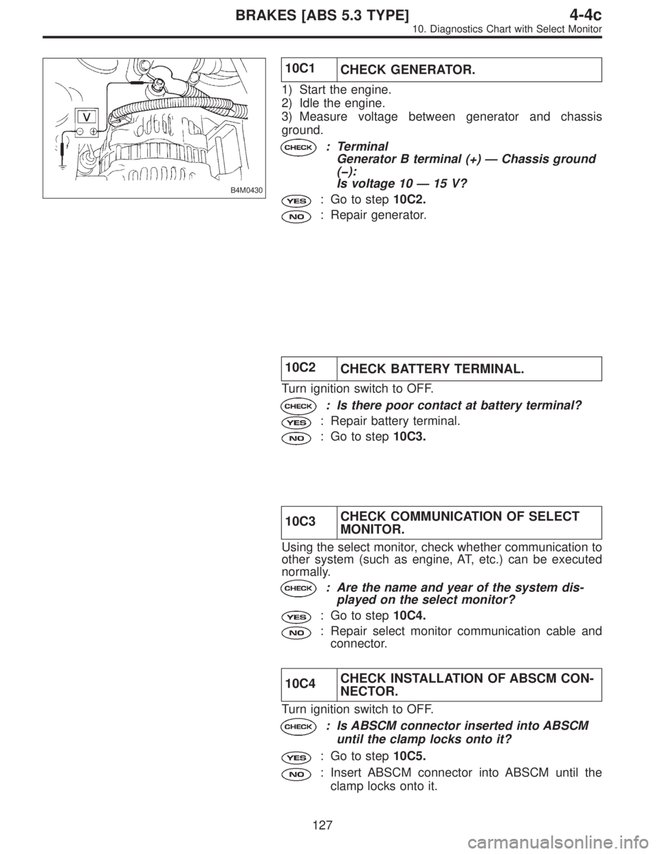
10C1
CHECK GENERATOR.
1) Start the engine.
2) Idle the engine.
3) Measure voltage between generator and chassis
ground.
: Terminal
Generator B terminal (+)—Chassis ground
(�):
Is voltage 10—15 V?
: Go to step10C2.
: Repair generator.
10C2
CHECK BATTERY TERMINAL.
Turn ignition switch to OFF.
: Is there poor contact at battery terminal?
: Repair battery terminal.
: Go to step10C3.
10C3CHECK COMMUNICATION OF SELECT
MONITOR.
Using the select monitor, check whether communication to
other system (such as engine, AT, etc.) can be executed
normally.
: Are the name and year of the system dis-
played on the select monitor?
: Go to step10C4.
: Repair select monitor communication cable and
connector.
10C4CHECK INSTALLATION OF ABSCM CON-
NECTOR.
Turn ignition switch to OFF.
: Is ABSCM connector inserted into ABSCM
until the clamp locks onto it?
: Go to step10C5.
: Insert ABSCM connector into ABSCM until the
clamp locks onto it.
127
4-4cBRAKES [ABS 5.3 TYPE]
10. Diagnostics Chart with Select Monitor
Page 2612 of 2890
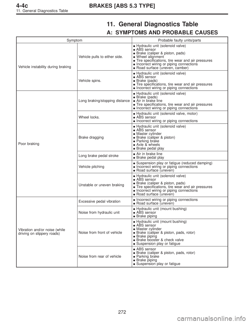
11. General Diagnostics Table
A: SYMPTOMS AND PROBABLE CAUSES
Symptom Probable faulty units/parts
Vehicle instability during brakingVehicle pulls to either side.�Hydraulic unit (solenoid valve)
�ABS sensor
�Brake (caliper & piston, pads)
�Wheel alignment
�Tire specifications, tire wear and air pressures
�Incorrect wiring or piping connections
�Road surface (uneven, camber)
Vehicle spins.�Hydraulic unit (solenoid valve)
�ABS sensor
�Brake (pads)
�Tire specifications, tire wear and air pressures
�Incorrect wiring or piping connections
Poor brakingLong braking/stopping distance�Hydraulic unit (solenoid valve)
�Brake (pads)
�Air in brake line
�Tire specifications, tire wear and air pressures
�Incorrect wiring or piping connections
Wheel locks.�Hydraulic unit (solenoid valve, motor)
�ABS sensor
�Incorrect wiring or piping connections
Brake dragging�Hydraulic unit (solenoid valve)
�ABS sensor
�Master cylinder
�Brake (caliper & piston)
�Parking brake
�Axle & wheels
�Brake pedal play
Long brake pedal stroke�Air in brake line
�Brake pedal play
Vehicle pitching�Suspension play or fatigue (reduced damping)
�Incorrect wiring or piping connections
�Road surface (uneven)
Unstable or uneven braking�Hydraulic unit (solenoid valve)
�ABS sensor
�Brake (caliper & piston, pads)
�Tire specifications, tire wear and air pressures
�Incorrect wiring or piping connections
�Road surface (uneven)
Vibration and/or noise (while
driving on slippery roads)Excessive pedal vibration�Incorrect wiring or piping connections
�Road surface (uneven)
Noise from hydraulic unit�Hydraulic unit (mount bushing)
�ABS sensor
�Brake piping
Noise from front of vehicle�Hydraulic unit (mount bushing)
�ABS sensor
�Master cylinder
�Brake (caliper & piston, pads, rotor)
�Brake piping
�Brake booster & check valve
�Suspension play or fatigue
Noise from rear of vehicle�ABS sensor
�Brake (caliper & piston, pads, rotor)
�Parking brake
�Brake piping
�Suspension play or fatigue
272
4-4cBRAKES [ABS 5.3 TYPE]
11. General Diagnostics Table
Page 2626 of 2890
![SUBARU LEGACY 1996 Service Repair Manual 24) Turn ignition switch“OFF”, disconnect battery ground cable,
and wait 20 seconds. Remove driver side airbag module and
connect test harness C connector (1C) to (AB7) <Ref. to 5-5
[W3A1].> with SUBARU LEGACY 1996 Service Repair Manual 24) Turn ignition switch“OFF”, disconnect battery ground cable,
and wait 20 seconds. Remove driver side airbag module and
connect test harness C connector (1C) to (AB7) <Ref. to 5-5
[W3A1].> with](/manual-img/17/57433/w960_57433-2625.png)
24) Turn ignition switch“OFF”, disconnect battery ground cable,
and wait 20 seconds. Remove driver side airbag module and
connect test harness C connector (1C) to (AB7)
[W3A1].> with airbag resistor attached to test harness C con-
nector (3C).
G5M0430
25) Reconnect battery ground cable and turn ignition switch“ON”. Does airbag warning light go“OFF”after 8 seconds and remain off
for more than 30 seconds? See notes 1) and 2). (Refer to end of chart.) If“YES”, proceed to step 26). If“NO”, proceed to step
27).
26) Turn ignition switch“OFF”, disconnect battery ground cable, and wait 20 seconds. Install driver side airbag module
[W3B0].> and proceed to step 27).
27) Replace combination switch, and proceed to step 26).
28) Reconnect battery and turn ignition switch“ON”. Does airbag warning light go off after 8 seconds and remain off for more than 30
seconds? See notes 1) and 2). (Refer to end of chart.) If“YES”, proceed to step 29). If“NO”, proceed to step 31).
29) Perform clear memory procedure.
30) If memory cannot be cleared, another trouble code exists. Return to step 1).
31) Turn ignition switch“OFF”, disconnect battery ground cable, and wait 20 seconds. Replace driver side airbag module.
5-5 [W3A1].> Proceed to step 28).
NOTES:
1) Always remember to secure the green double locks before turning the ignition switch “ON”.
2) In some cases the airbag warning light will go “OFF” after 8 seconds but will turn “ON” again within 30 seconds. In this
case continue diagnostics with the basic diagnostics procedures or trouble code procedures.
14
5-5SUPPLEMENTAL RESTRAINT SYSTEM
4. Diagnostics Chart for On-board Diagnostic System