Page 2437 of 2890
3) Turn ignition switch to OFF.
4) Measure voltage between motor relay installing point
and chassis ground.
: Connector & terminal
Motor relay installing point (+) No. 86—
Chassis ground
Motor relay installing point (+) No. 85—
Chassis ground
Is voltage 0 V?
: Go to step8L13.
: Replace relay box and check all fuses.
B4M0898B
8L13CHECK BROKEN WIRE IN MONITOR
SYSTEM HARNESS.
1) Connect between terminals No. 10 and No. 1 of
ABSCM connector (F49) with a lead wire.
2) Measure resistance between relay box connector and
chassis ground.
: Connector & terminal
(F50) No. 6—Chassis ground
Is resistance less than 0.5Ω?
: Go to step8L14.
: Repair harness connector between ABSCM and
relay box.
97
4-4cBRAKES [ABS 5.3 TYPE]
8. Diagnostics Chart with Trouble Code
Page 2438 of 2890
B4M0899A
8L14CHECK BROKEN WIRE IN RELAY CON-
TROL SYSTEM HARNESS.
1) Connect valve relay and motor relay to relay box.
2) Connect connector (F50) to relay box.
3) Connect connector to hydraulic unit.
4) Measure resistance between ABSCM connector and
chassis ground.
: Connector & terminal
(F49) No. 22—Chassis ground
Is resistance 80±10Ω?
: Go to step8L15.
: Repair harness connector between ABSCM and
relay box.
B4M0900A
8L15CHECK GROUND SHORT BETWEEN
RELAY BOX AND ABSCM.
1) Disconnect connector (F50) from relay box.
2) Measure resistance between ABSCM connector and
chassis ground.
: Connector & terminal
(F49) No. 22—Chassis ground
(F49) No. 10—Chassis ground
Is resistance more than 1 MΩ?
: Go to step8L16.
: Repair harness between ABSCM and relay box.
Check fuse No. 19 and SBF6.
98
4-4cBRAKES [ABS 5.3 TYPE]
8. Diagnostics Chart with Trouble Code
Page 2439 of 2890

B4M0901A
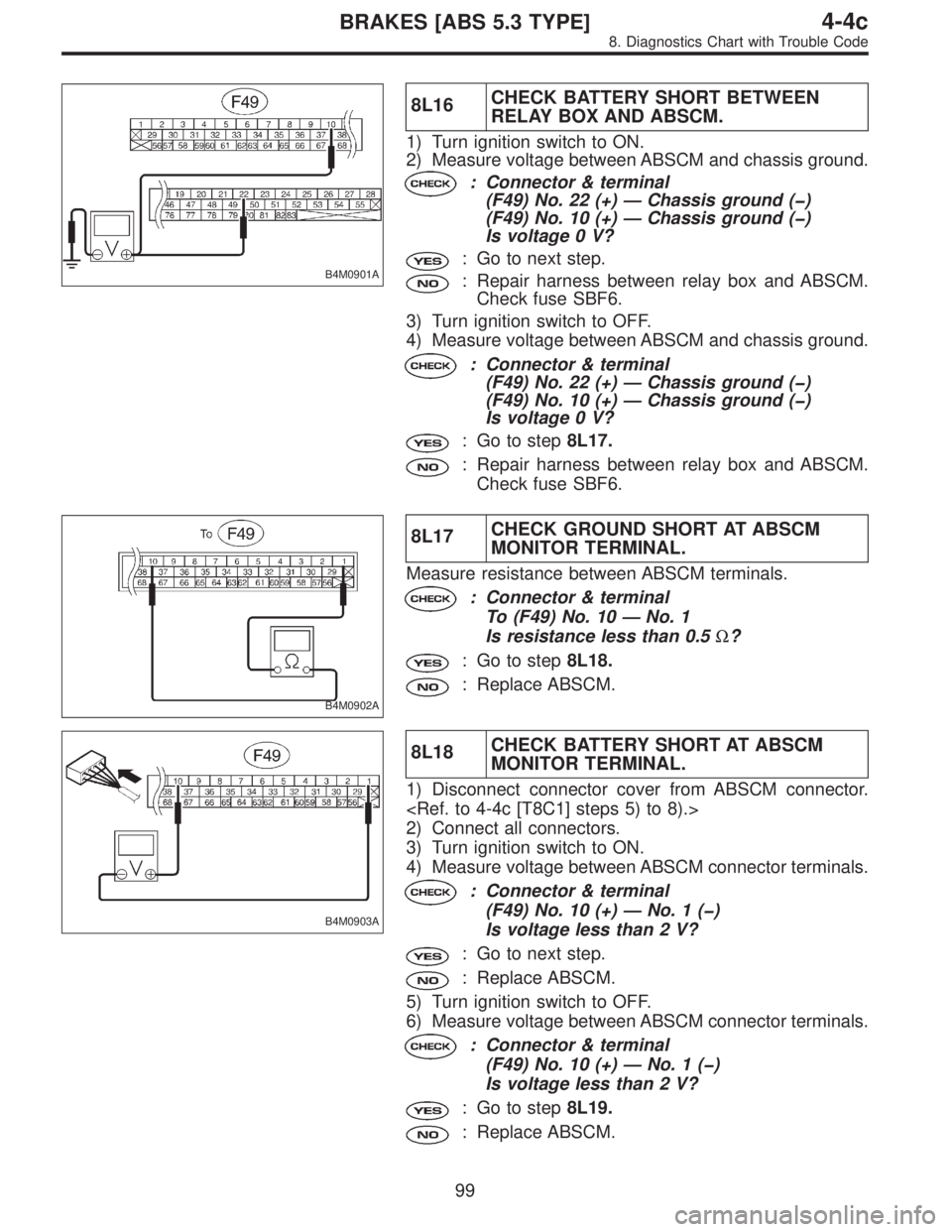
8L16CHECK BATTERY SHORT BETWEEN
RELAY BOX AND ABSCM.
1) Turn ignition switch to ON.
2) Measure voltage between ABSCM and chassis ground.
: Connector & terminal
(F49) No. 22 (+)—Chassis ground (�)
(F49) No. 10 (+)—Chassis ground (�)
Is voltage 0 V?
: Go to next step.
: Repair harness between relay box and ABSCM.
Check fuse SBF6.
3) Turn ignition switch to OFF.
4) Measure voltage between ABSCM and chassis ground.
: Connector & terminal
(F49) No. 22 (+)—Chassis ground (�)
(F49) No. 10 (+)—Chassis ground (�)
Is voltage 0 V?
: Go to step8L17.
: Repair harness between relay box and ABSCM.
Check fuse SBF6.
B4M0902A
8L17CHECK GROUND SHORT AT ABSCM
MONITOR TERMINAL.
Measure resistance between ABSCM terminals.
: Connector & terminal
To (F49) No. 10—No. 1
Is resistance less than 0.5Ω?
: Go to step8L18.
: Replace ABSCM.
B4M0903A
8L18CHECK BATTERY SHORT AT ABSCM
MONITOR TERMINAL.
1) Disconnect connector cover from ABSCM connector.
2) Connect all connectors.
3) Turn ignition switch to ON.
4) Measure voltage between ABSCM connector terminals.
: Connector & terminal
(F49) No. 10 (+)—No.1(�)
Is voltage less than 2 V?
: Go to next step.
: Replace ABSCM.
5) Turn ignition switch to OFF.
6) Measure voltage between ABSCM connector terminals.
: Connector & terminal
(F49) No. 10 (+)—No.1(�)
Is voltage less than 2 V?
: Go to step8L19.
: Replace ABSCM.
99
4-4cBRAKES [ABS 5.3 TYPE]
8. Diagnostics Chart with Trouble Code
Page 2444 of 2890
B4M0908A
8M2
CHECK OPEN CIRCUIT OF HARNESS.
1) Turn ignition switch to OFF.
2) Disconnect connector from ABSCM.
3) Depress brake pedal.
4) Measure voltage between ABSCM connector and chas-
sis ground.
: Connector & terminal
(F49) No. 36—Chassis ground
Is voltage 10—13 V?
: Go to step8M3.
: Repair harness between stop light switch and
ABSCM.
8M3CHECK POOR CONTACT IN CONNEC-
TOR BETWEEN STOP LIGHT SWITCH
AND ABSCM.
: Is there poor contact in connector between
stop light switch and ABSCM?
: Repair connector.
: Go to step8M4.
8M4
CHECK ABSCM.
1) Connect all connectors.
2) Erase the memory.
3) Perform inspection mode.
4) Read out the trouble code.
: Is the same trouble code as in the current
diagnosis still being output?
: Replace ABSCM.
: Go to next.
: Are other trouble codes being output?
: Proceed with the diagnosis corresponding to the
trouble code.
: A temporary poor contact.
104
4-4cBRAKES [ABS 5.3 TYPE]
8. Diagnostics Chart with Trouble Code
Page 2448 of 2890
B4M0913A
8N5CHECK GROUND SHORT IN G SENSOR
OUTPUT HARNESS.
1) Disconnect connector from G sensor.
2) Measure resistance between ABSCM connector and
chassis ground.
: Connector & terminal
(F49) No. 7—Chassis ground
Is resistance more than 1 MΩ?
: Go to step8N6.
: Repair harness between G sensor and ABSCM.
B4M0914A
8N6
CHECK BATTERY SHORT OF HARNESS.
1) Turn ignition switch to ON.
2) Measure voltage between ABSCM connector and chas-
sis ground.
: Connector & terminal
(F49) No. 7 (+)—Chassis ground (�)
Is voltage 0 V?
: Go to next step.
: Repair harness between G sensor and ABSCM.
3) Turn ignition switch to OFF.
4) Measure voltage between ABSCM connector and chas-
sis ground.
: Connector & terminal
(F49) No. 7 (+)—Chassis ground (�)
Is voltage 0 V?
: Go to step8N7.
: Repair harness between G sensor and ABSCM.
108
4-4cBRAKES [ABS 5.3 TYPE]
8. Diagnostics Chart with Trouble Code
Page 2467 of 2890

B4M0430
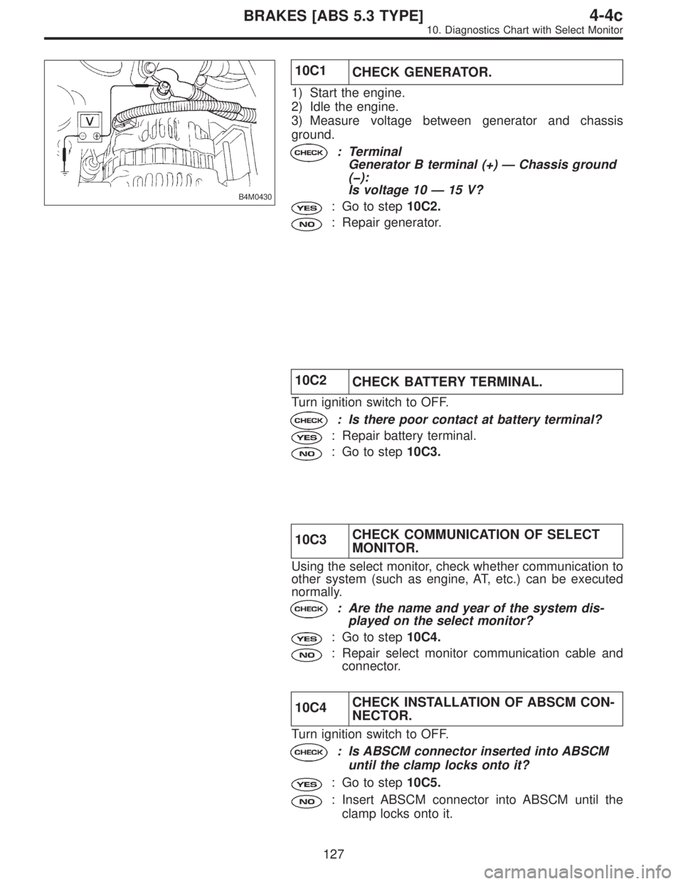
10C1
CHECK GENERATOR.
1) Start the engine.
2) Idle the engine.
3) Measure voltage between generator and chassis
ground.
: Terminal
Generator B terminal (+)—Chassis ground
(�):
Is voltage 10—15 V?
: Go to step10C2.
: Repair generator.
10C2
CHECK BATTERY TERMINAL.
Turn ignition switch to OFF.
: Is there poor contact at battery terminal?
: Repair battery terminal.
: Go to step10C3.
10C3CHECK COMMUNICATION OF SELECT
MONITOR.
Using the select monitor, check whether communication to
other system (such as engine, AT, etc.) can be executed
normally.
: Are the name and year of the system dis-
played on the select monitor?
: Go to step10C4.
: Repair select monitor communication cable and
connector.
10C4CHECK INSTALLATION OF ABSCM CON-
NECTOR.
Turn ignition switch to OFF.
: Is ABSCM connector inserted into ABSCM
until the clamp locks onto it?
: Go to step10C5.
: Insert ABSCM connector into ABSCM until the
clamp locks onto it.
127
4-4cBRAKES [ABS 5.3 TYPE]
10. Diagnostics Chart with Select Monitor
Page 2468 of 2890
B4M0796A
10C5
CHECK POWER SUPPLY OF ABSCM.
1) Disconnect connector from ABSCM.
2) Start engine.
3) Idle the engine.
4) Measure voltage between ABSCM connector and chas-
sis ground.
: Connector & terminal
(F49) No. 28 (+)—Chassis ground (�):
Is voltage 10—15 V?
: Go to step10C6.
: Repair ABSCM power supply circuit.
B4M0797A
10C6
CHECK GROUND CIRCUIT OF ABSCM.
1) Turn ignition switch to OFF.
2) Measure resistance between ABSCM connector and
chassis ground.
: Connector & terminal
(F49) No. 1—Chassis ground:
(F49) No. 55—Chassis ground:
Is resistance less than 0.5Ω?
: Repair harness/connector between ABSCM and
select monitor.
: Go to step10C7.
128
4-4cBRAKES [ABS 5.3 TYPE]
10. Diagnostics Chart with Select Monitor
Page 2478 of 2890

B4M0806B
B4M1036A
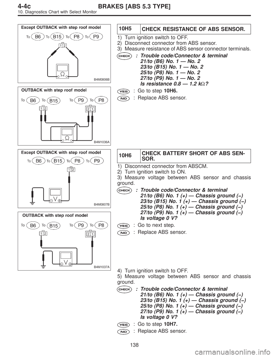
10H5
CHECK RESISTANCE OF ABS SENSOR.
1) Turn ignition switch to OFF.
2) Disconnect connector from ABS sensor.
3) Measure resistance of ABS sensor connector terminals.
: Trouble code/Connector & terminal
21/to (B6) No. 1—No. 2
23/to (B15) No. 1—No. 2
25/to (P8) No. 1—No. 2
27/to (P9) No. 1—No. 2
Is resistance 0.8—1.2 kΩ?
: Go to step10H6.
: Replace ABS sensor.
B4M0807B
B4M1037A
10H6CHECK BATTERY SHORT OF ABS SEN-
SOR.
1) Disconnect connector from ABSCM.
2) Turn ignition switch to ON.
3) Measure voltage between ABS sensor and chassis
ground.
: Trouble code/Connector & terminal
21/to (B6) No. 1 (+)—Chassis ground (�)
23/to (B15) No. 1 (+)—Chassis ground (�)
25/to (P8) No. 1 (+)—Chassis ground (�)
27/to (P9) No. 1 (+)—Chassis ground (�)
Is voltage 0 V?
: Go to next step.
: Replace ABS sensor.
4) Turn ignition switch to OFF.
5) Measure voltage between ABS sensor and chassis
ground.
: Trouble code/Connector & terminal
21/to (B6) No. 1 (+)—Chassis ground (�)
23/to (B15) No. 1 (+)—Chassis ground (�)
25/to (P8) No. 1 (+)—Chassis ground (�)
27/to (P9) No. 1 (+)—Chassis ground (�)
Is voltage 0 V?
: Go to step10H7.
: Replace ABS sensor.
138
4-4cBRAKES [ABS 5.3 TYPE]
10. Diagnostics Chart with Select Monitor