Page 1191 of 2890
![SUBARU LEGACY 1996 Service Repair Manual 2. MEASUREMENT OF HYDRAULIC PRESSURE
CAUTION:
Be sure to complete all items aforementioned in
“STEERING CONDITION”4-3 [K101], prior to measur-
ing hydraulic pressure. Otherwise, pressure can not b](/manual-img/17/57433/w960_57433-1190.png "SUBARU LEGACY 1996 Service Repair Manual 2. MEASUREMENT OF HYDRAULIC PRESSURE
CAUTION:
Be sure to complete all items aforementioned in
“STEERING CONDITION”4-3 [K101], prior to measur-
ing hydraulic pressure. Otherwise, pressure can not b")
2. MEASUREMENT OF HYDRAULIC PRESSURE
CAUTION:
Be sure to complete all items aforementioned in
“STEERING CONDITION”4-3 [K101], prior to measur-
ing hydraulic pressure. Otherwise, pressure can not be
measured correctly.
Measure regular pressure at
idling with valve opened.
GOOD
�NOT GOOD
Flattened pipes or hoses�Replace bad parts.
�NOT GOOD
Leakage of fluid line�Replace.
�NOT GOOD
Obstacle in fluid line�Replace fluid or component of
fluid line.
Measure relief pressure at
idling with valve closed.
GOOD
�NOT GOOD
Poor work of relief valve�Replace oil pump.
�NOT GOOD
Fluid leakage inside oil pump�
�NOT GOOD
Excessive wear of vane pump
mechanism�
Measure working pressure of
control valve at idling with
valve opened, turning steering
wheel from stop to stop.�NOT GOOD
Poor work of control valve�Replace valve assembly or
pinion and valve assembly.
CAUTION:
�Do not leave the valve of pressure gauge closed or
hold the steering wheel at stop end for 5 seconds or
more in any case, as the oil pump may be damaged
due to long keep of these conditions.
�Put cotton cloth waste at a place where fluid drops
before pressure gauge is installed. Wipe off split fluid
thoroughly after the measurement.
NOTE:
Keep engine idling during the measurement.
�
�
84
4-3DIAGNOSTICS
1. Power Steering
Page 1192 of 2890
G4M0195
1) Using STs, measure regulator pressure.
Regulator pressure:
981 kPa (10 kg/cm
2, 142 psi) or less
ST1 925711000 PRESSURE GAUGE
ST2 926220000 ADAPTER B
ST3 926210000 ADAPTER A
G4M0196
2) Using STs, measure relief pressure.
Relief pressure:
7,159—7,748 kPa
(73—79 kg/cm
2, 1,038—1,123 psi)
ST1 925711000 PRESSURE GAUGE
ST2 926220000 ADAPTER B
ST3 926210000 ADAPTER A
85
4-3DIAGNOSTICS
1. Power Steering
Page 1193 of 2890
 or less in both directions
GOOD
�NOT GOOD
Adjust backl")
3. MEASUREMENT OF STEERING EFFORT
*4
Measure steering efforts in stand still with engine idling on
concrete road.
Result: 29.4 N (3.0 kg, 6.6 lb) or less in both directions
GOOD
�NOT GOOD
Adjust backlash.
Measure steering efforts in stand still with engine stalled on
concrete road.
Result: 294.2 N (30.0 kg, 66.2 lb) or less in both directions
NOT GOOD GOOD*4 When turning steering more
quickly than necessary from
a direction to the other direc-
tion at an engine speed over
2,000 rpm, steering effort
may be heavy. This is caused
by flow characteristic of oil
pump and is not a problem.
Adjust backlash.
Remove universal joint.
Measure steering wheel effort.
Result: Maximum force is 2.26 N (0.23 kg, 0.51 lb) or less in
both directions.
Fluctuation width is 1.08 N (0.11 kg, 0.24 lb) or less.
GOOD
�NOT GOOD
Check, readjust, replace if
necessary.
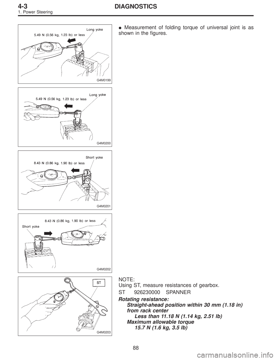
Measure folding torque of the joint.
Result: 5.49 N (0.56 kg, 1.23 lb) or less for long yoke
8.43 N (0.86 kg, 1.90 lb) or less for short yoke
GOOD
�NOT GOOD
Replace with a new one.
Check front wheels for unsteady revolution or rattling and brake
for dragging.
GOOD
�NOT GOOD
Inspect, readjust, replace if
necessary.
Remove tie-rod ends.
(To be continued.)
�
�
�
�
�
�
�
�
86
4-3DIAGNOSTICS
1. Power Steering
Page 1194 of 2890
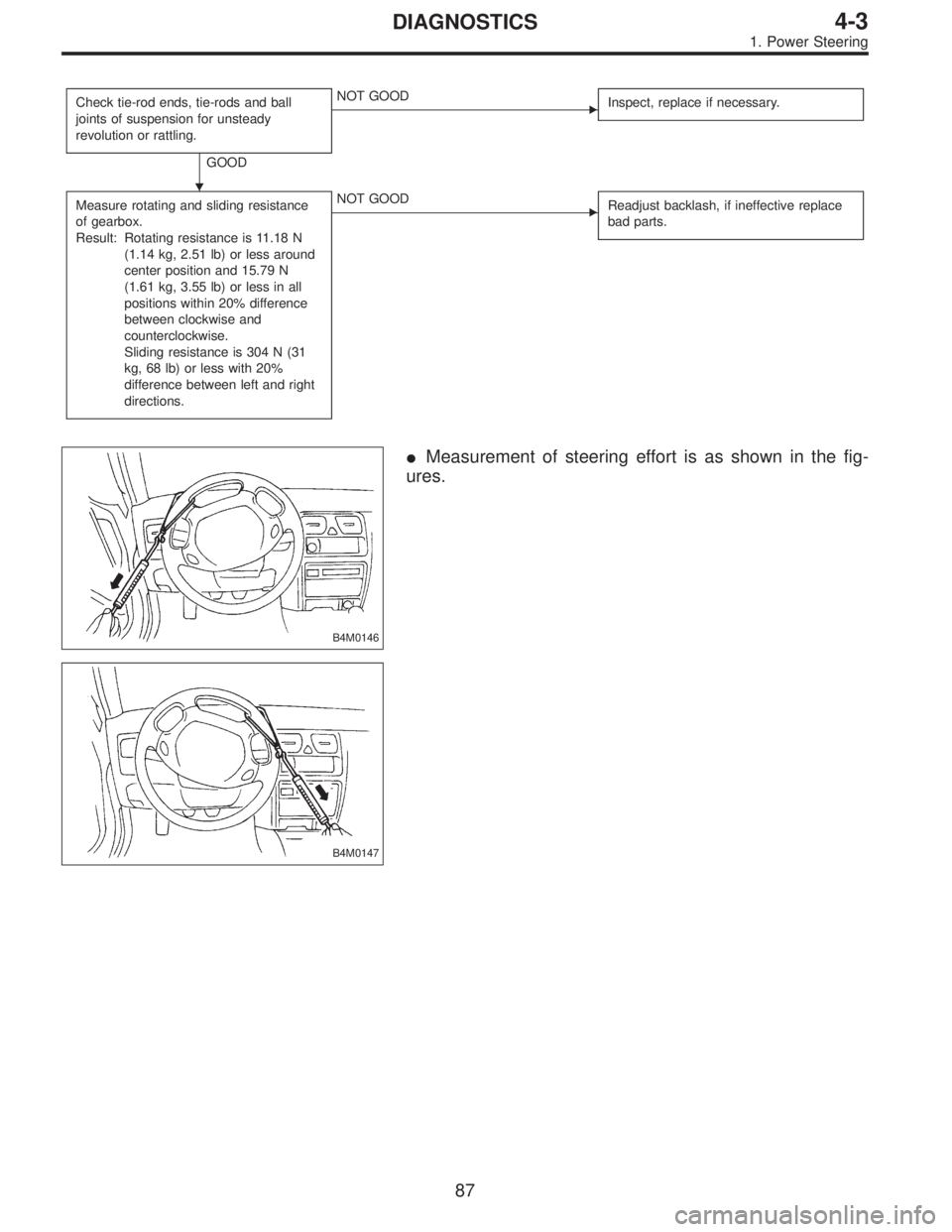
Check tie-rod ends, tie-rods and ball
joints of suspension for unsteady
revolution or rattling.
GOOD
�NOT GOOD
Inspect, replace if necessary.
Measure rotating and sliding resistance
of gearbox.
Result: Rotating resistance is 11.18 N
(1.14 kg, 2.51 lb) or less around
center position and 15.79 N
(1.61 kg, 3.55 lb) or less in all
positions within 20% difference
between clockwise and
counterclockwise.
Sliding resistance is 304 N (31
kg, 68 lb) or less with 20%
difference between left and right
directions.�NOT GOOD
Readjust backlash, if ineffective replace
bad parts.
B4M0146
�Measurement of steering effort is as shown in the fig-
ures.
B4M0147
�
87
4-3DIAGNOSTICS
1. Power Steering
Page 1195 of 2890
G4M0199
�Measurement of folding torque of universal joint is as
shown in the figures.
G4M0200
G4M0201
G4M0202
G4M0203
NOTE:
Using ST, measure resistances of gearbox.
ST 926230000 SPANNER
Rotating resistance:
Straight-ahead position within 30 mm (1.18 in)
from rack center
Less than 11.18 N (1.14 kg, 2.51 lb)
Maximum allowable torque
15.7 N (1.6 kg, 3.5 lb)
88
4-3DIAGNOSTICS
1. Power Steering
Page 1196 of 2890
G4M0204
Sliding resistance:
Right-turn steering
304 N (31 kg, 68 lb) or less
Left-turn steering
304 N (31 kg, 68 lb) or less
G4M0205
89
4-3DIAGNOSTICS
1. Power Steering
Page 1197 of 2890

CAUTION:
It is likely that although one judges fluid leakage, there
is actually no leakage. This is because the fluid spilt
during the last maintenance was not completely")
4. FLUID LEAKAGE (LHD MODEL)
CAUTION:
It is likely that although one judges fluid leakage, there
is actually no leakage. This is because the fluid spilt
during the last maintenance was not completely wiped
off. Be sure to wipe off spilt fluid thoroughly after
maintenance.
Leakage from connecting portions of
pipes and hoses, numbered with�1thru�9in figure
�Insufficient tightening of flare nut,
catching dirt or the like, damage to
flare or flare nut�Loosen and retighten, if ineffective,
replace.
�Poor insertion of hose, poor clamp-
ing�Retighten or replace clamp.
�Damaged O-ring�Replace O-ring pipe or hose with
new one, if ineffective, replace gear-
box also.
Leakage from hose�10and�11in
figure�Crack or damage in hose�Replace with a new one.
�Crack or damage in hose hardware�
Leakage from surrounding of cast
iron portion of oil pump�12and�13in
figure�Damaged oil seal�Replace oil seal.
�Damaged oil seal�
Leakage from oil tank,�14and�15in figure�Crack in oil tank,�14�Replace oil tank.
�Damaged O-ring,�15�Replace O-ring.
Leakage from filler neck�16�Damaged cap packing�Replace cap.
�Crack in root of filler neck�Replace oil tank.
�High fluid level *5�Adjust fluid level.
Leakage from surrounding of power
cylinder of gearbox,�17in figure�Damaged oil seal�Replace bad parts.
Leakage from control valve of
gearbox,�18and�19in figure�Damaged packing or oil seal�
�Damage in control valve�
*5 Fluid level is specified at optimum position (range) for ordinary use. Accordingly, if the vehicle is used often under hard con-
ditions such as on very rough roads or in mountainous areas, fluid may bleed out from cap air vent hole. This is not a prob-
lem. If a customer complains strongly and is not likely to be satisfied with the leakage, lower the fluid level to the extent that
fluid will not bleed out under the conditions described, and have the customer check the fluid level and its quality more fre-
quency than usual.
90
4-3DIAGNOSTICS
1. Power Steering
Page 1198 of 2890
B4M0564A
91
4-3DIAGNOSTICS
1. Power Steering
 Using STs, measure regulator pressure.
Regulator pressure:
981 kPa (10 kg/cm
2, 142 psi) or less
ST1 925711000 PRESSURE GAUGE
ST2 926220000 ADAPTER B
ST3 926210000 ADAPTER A
G4M0196
2) Usin")
 or less
Left-turn steering
304 N (31 kg, 68 lb) or less
G4M0205
89
4-3DIAGNOSTICS
1. Power Steering")
