Page 1175 of 2890
 Remove flare nuts from control valve of gearbox
assembly, and then disconnect pipe C⋅D.
CAUTION:
�When disconnecting pipe C⋅D, use two wrenches to
prevent deformities.
�Be careful to keep pipe")
5) Remove flare nuts from control valve of gearbox
assembly, and then disconnect pipe C⋅D.
CAUTION:
�When disconnecting pipe C⋅D, use two wrenches to
prevent deformities.
�Be careful to keep pipe connections free from for-
eign matter.
B4M0556A
6) Remove bolt A.
Disconnect pipe C from oil pump. Disconnect pipe D from
oil tank.
CAUTION:
�Do not allow fluid from the hose end to come into
contact with pulley belt.
�To prevent foreign matter from entering the hose
and pipe, cover the open ends of them with a clean
cloth.
B: CHECK
Check all disassembled parts for wear, damage or other
abnormalities. Repair or replace faulty parts as required.
Part name Inspection Remedy
Pipe�O-ring fitting surface for
damage
�Nut for damage
�Pipe for damageReplace with new one.
Clamp
�Clamps for weak
clamping forceReplace with new one.
Clamp E
Hose�Flared surface for
damage
�Flare nut for damage
�Outer surface for cracks
�Outer surface for wear
�Clip for damage
�End coupling or adapter
for degradationReplace with new one.
68
4-3SERVICE PROCEDURE
8. Pipe Assembly (Power Steering System) [RHD model]
Page 1176 of 2890
B4M0556A
C: ASSEMBLY
1) Interconnect pipes C and D.
Tightening torque:
Joint nut
15±5 N⋅m (1.5±0.5 kg-m, 10.8±3.6 ft-lb)
CAUTION:
Visually check that hose between tank and pipe D is
free from bending or twisting.
2) Tighten bolt A.
Tightening torque:
13±3 N⋅m (1.3±0.3 kg-m, 9.4±2.2 ft-lb)
B4M0673A
3) Temporarily connect pipes C and D to control valve of
gearbox.
B4M0667A
4) Temporarily install clamp E on pipes C and D.
CAUTION:
Ensure that the letter“8”side of clamp E is on the pipe
C side as shown in the figure.
5) Tighten clamp E firmly.
Tightening torque:
7.4±2.0 N⋅m (0.75±0.20 kg-m, 5.4±1.4 ft-lb)
6) Tighten joint nut.
Tightening torque:
15±5 N⋅m (1.5±0.5 kg-m, 10.8±3.6 ft-lb)
69
4-3SERVICE PROCEDURE
8. Pipe Assembly (Power Steering System) [RHD model]
Page 1177 of 2890
B4M0671A
7) Connect pipes A and B to four pipe joints of gearbox.
Connect upper pipe A first, and lower pipe B second.
Tightening torque:
13±3 N⋅m (1.3±0.3 kg-m, 9.4±2.2 ft-lb)
8) Install jack-up plate.
9) Connect battery negative terminal.
10) Feed the specified fluid and discharge air.
NOTE:
Never start the engine before feeding the fluid; otherwise
vane pump might be seized up.
B4M0674A
70
4-3SERVICE PROCEDURE
8. Pipe Assembly (Power Steering System) [RHD model]
Page 1178 of 2890

A: REMOVAL
1) Remove ground cable from battery.
2) Drain the working fluid about 0.35�(0.4 US qt, 0.3 Imp
qt) from oil tank.
3) Remove pulley belt cover bra")
B4M0558
9. Oil Pump (Power Steering System)
A: REMOVAL
1) Remove ground cable from battery.
2) Drain the working fluid about 0.35�(0.4 US qt, 0.3 Imp
qt) from oil tank.
3) Remove pulley belt cover bracket.
B4M0559A
4) Loosen oil pump pulley nut, then remove bolts which
secure alternator.
5) Loosen pulley belt(s).
6) Remove the nut and detach oil pump pulley.
B4M0556A
7) Remove bolt A. Disconnect pipe C from oil pump. Dis-
connect pipe D from oil tank.
CAUTION:
�Do not allow fluid from the hose end to come into
contact with pulley belt.
�To prevent foreign matter from entering the hose
and pipe, cover the open ends of them with a clean
cloth.
�Except when only oil tank needs to be inspected,
detach oil tank and oil pump as a unit. Then separate
one from the other on a work bench to prevent oil from
spilling on any part of the engine.
B4M0560
8) Remove three bolts from the front side of oil pump and
detach the pump.
9) Remove three bolts from the lower side of bracket and
detach the bracket.
CAUTION:
The bracket does not need to be removed unless it is
damaged.
71
4-3SERVICE PROCEDURE
9. Oil Pump (Power Steering System)
Page 1179 of 2890
 Place oil pump in a vise, remove two bolts from oil tank
and detach oil tank.
CAUTION:
Do not place oil pump directly in the vise; use soft
pads and hold oil pump lightly to protect the p")
B4M0561A
10) Place oil pump in a vise, remove two bolts from oil tank
and detach oil tank.
CAUTION:
Do not place oil pump directly in the vise; use soft
pads and hold oil pump lightly to protect the pump.
B: CHECK
In accordance with the following table, check all removed
parts for wear and damage, and make repair or replace-
ment if necessary.
No. Parts Inspection Corrective action
1 Oil pump (Exterior)(1) Crack, damage or oil leakage Replace oil pump with a new one.
(2) Play of pulley shaftMeasure radial play and axial play.
If any of these exceeds the service limit,
replace oil pump with a new one.
4-3 [W9B1].>
2 Pulley(1) Damage Replace it with a new one.
(2) BendMeasure V ditch deflection.
If it exceeds the service limit, replace
pulley with a new one.
[W9B1].>
3 Cap Crack or damage Replace it with a new one.
4 Strainer(1) Clogging with dirt Wash it.
(2) Breakage Replace it with a new one.
5 Oil pump (Interior)(1) Defect or burning of vane pumpCheck resistance to rotation of pulley.
If it is past the service limit, replace oil
pump with a new one.
[W9B1].>
(2) Bend in the shaft or damage to
bearingOil pump emits a noise that is markedly
different in tone and loudness from a
sound of a new oil pump when turning with
a string put around its pulley, replace oil
pump with a new one.
6 O-ring Crack or deterioration Replace it with a new one.
7 Oil tank Crack, damage or oil leakage Replace it with a new one.
8 Bracket Crack or damage Replace it with a new one.
72
4-3SERVICE PROCEDURE
9. Oil Pump (Power Steering System)
Page 1180 of 2890

G4M0172
1. SERVICE LIMIT
Make a measurement as follows. If it exceeds the specified
service limit, replace the parts with new ones.
CAUTION:
�Fix oil pump on a vise to make a measurement. At
this time, hold oil pump with the least possible force
between two wood pieces.
�Do not set outside of flow control valve or pulley on
a vise; otherwise outside or pulley might be deformed.
Select properly sized wood pieces.
G4M0173
Play of pulley shaft
Service limit:
Radial play (Direction
)
0.4 mm (0.016 in) or less
Axial play (Direction
)
0.9 mm (0.035 in) or less
On condition:
P: 9.8 N (1.0 kg, 2.2 lb)
G4M0174
Ditch deflection of pulley
Service limit:
1.0 mm (0.039 in) or less
NOTE:
Read the value for one surface of V ditch, and then the
value for another off the dial.
G4M0175
Resistance to rotation of pulley
Service limit:
Maximum load; 9.22 N (0.94 kg, 2.07 lb) or less
NOTE:
�A rather higher value may be indicated when pulley
starts turning.
�Measure the load during rotation and make a judgment.
73
4-3SERVICE PROCEDURE
9. Oil Pump (Power Steering System)
Page 1181 of 2890
C: DISASSEMBLY
B4M0142A
�1Pulley
�
2Snap ring
�
3Bearing
�
4Oil seal
�
5Shaft
�
6Connector
�
7O-ring
�
8Spool valve�
9Spring
�
10Front casing
�
11Rear cover
�
12Knock pin
�
13Seal washer
�
14Cam ring
�
15Vane
�
16Rotor�
17Side plate
Tightening torque: N⋅m (kg-m, ft-lb)
T1: 16±2 (1.6±0.2, 11.6±1.4)
T2: 61±7 (6.2±0.7, 45.0±5.2)
T3: 74±5 (7.5±0.5, 54.2±3.6)
B4M0561A
1) Oil pump body
(1) Place oil pump in a vise, and remove two bolts
which secure tank.
CAUTION:
Do not place oil pump directly in vise; use soft pads
and hold oil pump lightly to protect it.
74
4-3SERVICE PROCEDURE
9. Oil Pump (Power Steering System)
Page 1182 of 2890
G4M0178
(2) Remove four bolts which secure rear cover.
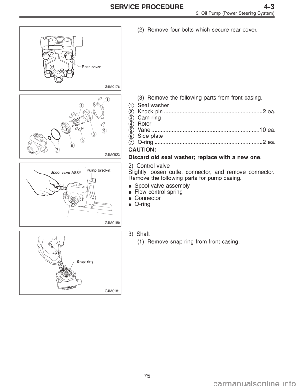
G4M0923
(3) Remove the following parts from front casing.
�
1Seal washer
�
2Knock pin ...............................................................2 ea.
�
3Cam ring
�
4Rotor
�
5Vane .....................................................................10 ea.
�
6Side plate
�
7O-ring .....................................................................2 ea.
CAUTION:
Discard old seal washer; replace with a new one.
G4M0180
2) Control valve
Slightly loosen outlet connector, and remove connector.
Remove the following parts for pump casing.
�Spool valve assembly
�Flow control spring
�Connector
�O-ring
G4M0181
3) Shaft
(1) Remove snap ring from front casing.
75
4-3SERVICE PROCEDURE
9. Oil Pump (Power Steering System)
 Interconnect pipes C and D.
Tightening torque:
Joint nut
15±5 N⋅m (1.5±0.5 kg-m, 10.8±3.6 ft-lb)
CAUTION:
Visually check that hose between tank and pipe D is
free from ben")
 Connect pipes A and B to four pipe joints of gearbox.
Connect upper pipe A first, and lower pipe B second.
Tightening torque:
13±3 N⋅m (1.3±0.3 kg-m, 9.4±2.2 ft-lb)
8) Install jack-up")