1996 CHRYSLER VOYAGER clutch
[x] Cancel search: clutchPage 1597 of 1938
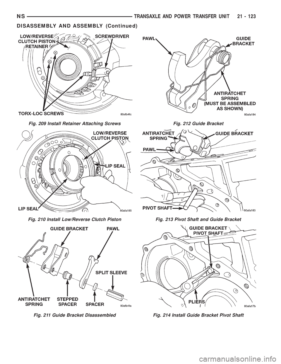
Fig. 209 Install Retainer Attaching Screws
Fig. 210 Install Low/Reverse Clutch Piston
Fig. 211 Guide Bracket Disassembled
Fig. 212 Guide Bracket
Fig. 213 Pivot Shaft and Guide Bracket
Fig. 214 Install Guide Bracket Pivot Shaft
NSTRANSAXLE AND POWER TRANSFER UNIT 21 - 123
DISASSEMBLY AND ASSEMBLY (Continued)
Page 1606 of 1938
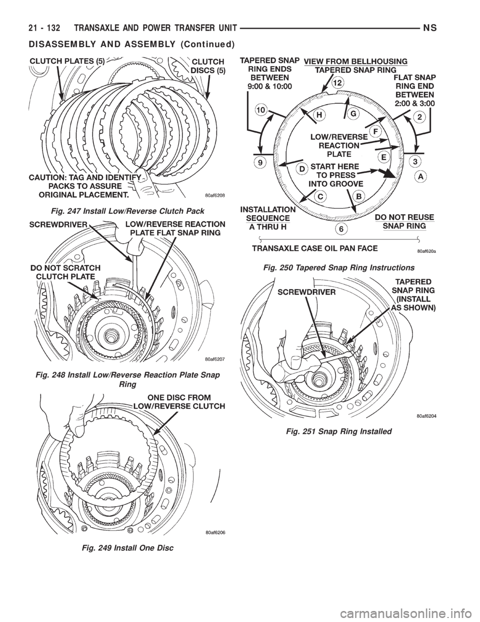
Fig. 247 Install Low/Reverse Clutch Pack
Fig. 248 Install Low/Reverse Reaction Plate Snap
Ring
Fig. 249 Install One Disc
Fig. 250 Tapered Snap Ring Instructions
Fig. 251 Snap Ring Installed
21 - 132 TRANSAXLE AND POWER TRANSFER UNITNS
DISASSEMBLY AND ASSEMBLY (Continued)
Page 1607 of 1938
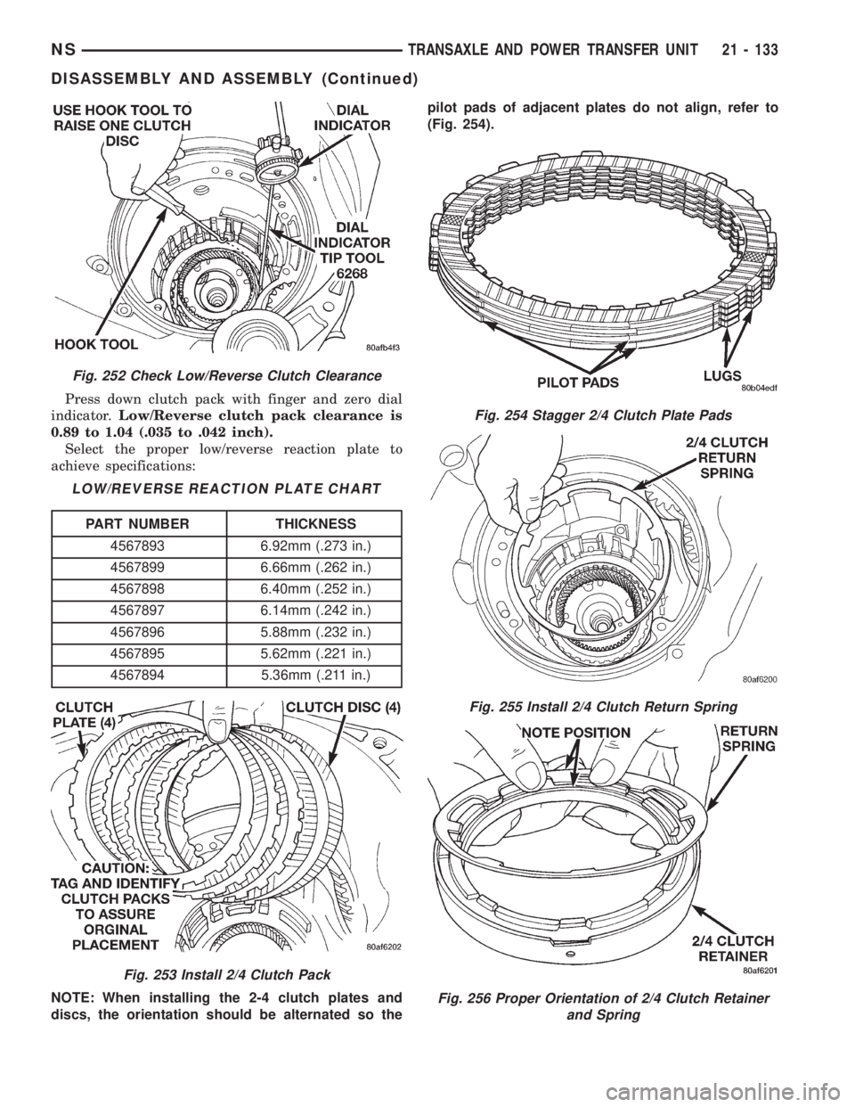
Press down clutch pack with finger and zero dial
indicator.Low/Reverse clutch pack clearance is
0.89 to 1.04 (.035 to .042 inch).
Select the proper low/reverse reaction plate to
achieve specifications:
NOTE: When installing the 2-4 clutch plates and
discs, the orientation should be alternated so thepilot pads of adjacent plates do not align, refer to
(Fig. 254).
Fig. 252 Check Low/Reverse Clutch Clearance
LOW/REVERSE REACTION PLATE CHART
PART NUMBER THICKNESS
4567893 6.92mm (.273 in.)
4567899 6.66mm (.262 in.)
4567898 6.40mm (.252 in.)
4567897 6.14mm (.242 in.)
4567896 5.88mm (.232 in.)
4567895 5.62mm (.221 in.)
4567894 5.36mm (.211 in.)
Fig. 253 Install 2/4 Clutch Pack
Fig. 254 Stagger 2/4 Clutch Plate Pads
Fig. 255 Install 2/4 Clutch Return Spring
Fig. 256 Proper Orientation of 2/4 Clutch Retainer
and Spring
NSTRANSAXLE AND POWER TRANSFER UNIT 21 - 133
DISASSEMBLY AND ASSEMBLY (Continued)
Page 1608 of 1938
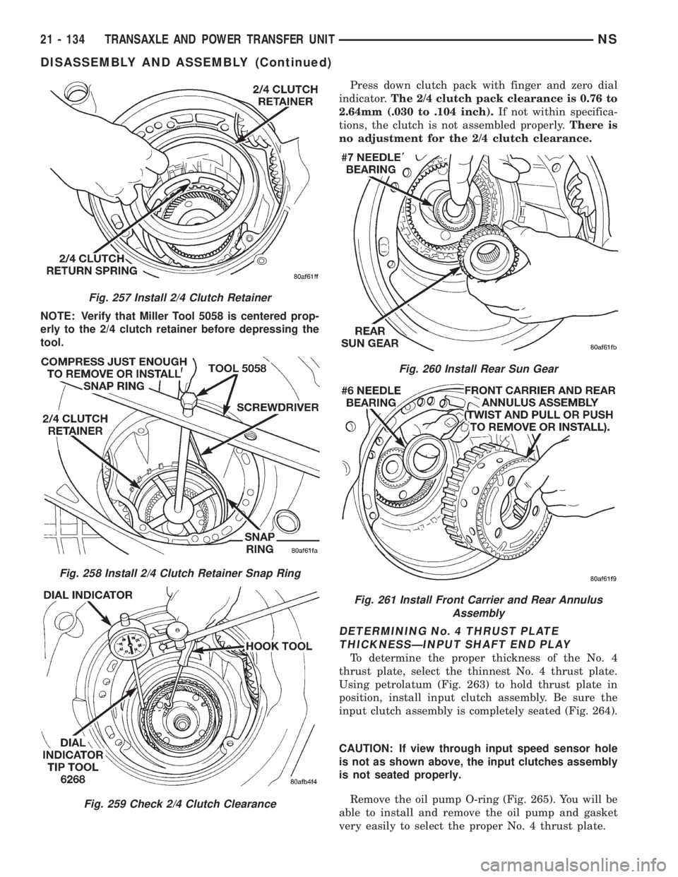
NOTE: Verify that Miller Tool 5058 is centered prop-
erly to the 2/4 clutch retainer before depressing the
tool.Press down clutch pack with finger and zero dial
indicator.The 2/4 clutch pack clearance is 0.76 to
2.64mm (.030 to .104 inch).If not within specifica-
tions, the clutch is not assembled properly.There is
no adjustment for the 2/4 clutch clearance.
DETERMINING No. 4 THRUST PLATE
THICKNESSÐINPUT SHAFT END PLAY
To determine the proper thickness of the No. 4
thrust plate, select the thinnest No. 4 thrust plate.
Using petrolatum (Fig. 263) to hold thrust plate in
position, install input clutch assembly. Be sure the
input clutch assembly is completely seated (Fig. 264).
CAUTION: If view through input speed sensor hole
is not as shown above, the input clutches assembly
is not seated properly.
Remove the oil pump O-ring (Fig. 265). You will be
able to install and remove the oil pump and gasket
very easily to select the proper No. 4 thrust plate.
Fig. 257 Install 2/4 Clutch Retainer
Fig. 258 Install 2/4 Clutch Retainer Snap Ring
Fig. 259 Check 2/4 Clutch Clearance
Fig. 260 Install Rear Sun Gear
Fig. 261 Install Front Carrier and Rear Annulus
Assembly
21 - 134 TRANSAXLE AND POWER TRANSFER UNITNS
DISASSEMBLY AND ASSEMBLY (Continued)
Page 1610 of 1938
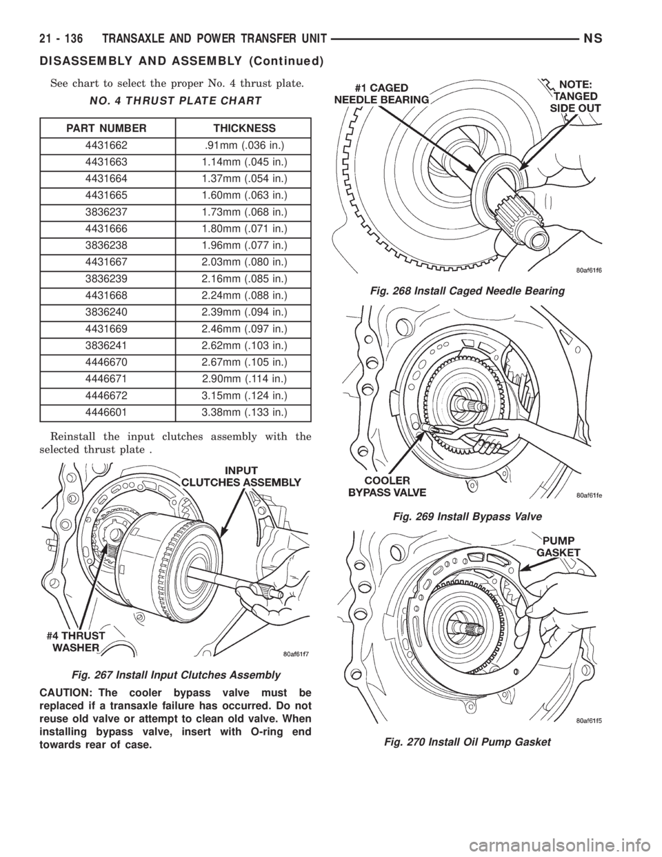
See chart to select the proper No. 4 thrust plate.
Reinstall the input clutches assembly with the
selected thrust plate .
CAUTION: The cooler bypass valve must be
replaced if a transaxle failure has occurred. Do not
reuse old valve or attempt to clean old valve. When
installing bypass valve, insert with O-ring end
towards rear of case.
NO. 4 THRUST PLATE CHART
PART NUMBER THICKNESS
4431662 .91mm (.036 in.)
4431663 1.14mm (.045 in.)
4431664 1.37mm (.054 in.)
4431665 1.60mm (.063 in.)
3836237 1.73mm (.068 in.)
4431666 1.80mm (.071 in.)
3836238 1.96mm (.077 in.)
4431667 2.03mm (.080 in.)
3836239 2.16mm (.085 in.)
4431668 2.24mm (.088 in.)
3836240 2.39mm (.094 in.)
4431669 2.46mm (.097 in.)
3836241 2.62mm (.103 in.)
4446670 2.67mm (.105 in.)
4446671 2.90mm (.114 in.)
4446672 3.15mm (.124 in.)
4446601 3.38mm (.133 in.)
Fig. 267 Install Input Clutches Assembly
Fig. 268 Install Caged Needle Bearing
Fig. 269 Install Bypass Valve
Fig. 270 Install Oil Pump Gasket
21 - 136 TRANSAXLE AND POWER TRANSFER UNITNS
DISASSEMBLY AND ASSEMBLY (Continued)
Page 1632 of 1938
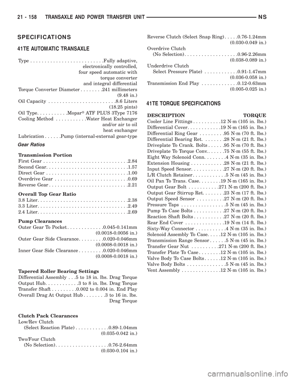
SPECIFICATIONS
41TE AUTOMATIC TRANSAXLE
Type..........................Fully adaptive,
electronically controlled,
four speed automatic with
torque converter
and integral differential
Torque Converter Diameter........241 millimeters
(9.48 in.)
Oil Capacity........................8.6 Liters
(18.25 pints)
OilType...........MopartATF PLUS 3Type 7176
Cooling Method...........Water Heat Exchanger
and/or air to oil
heat exchanger
Lubrication......Pump (internal-external gear-type
Gear Ratios
Transmission Portion
First Gear..............................2.84
Second Gear.............................1.57
Direct Gear.............................1.00
Overdrive Gear..........................0.69
Reverse Gear............................2.21
Overall Top Gear Ratio
3.8 Liter................................2.38
3.3 Liter................................2.49
2.4 Liter................................2.69
Pump Clearances
Outer Gear To Pocket.............0.045-0.141mm
(0.0018-0.0056 in.)
Outer Gear Side Clearance.........0.020-0.046mm
(0.0008-0.0018 in.)
Inner Gear Side Clearance.........0.020-0.046mm
(0.0008-0.0018 in.)
Tapered Roller Bearing Settings
Differential Assembly . . .5 to 18 in. lbs. Drag Torque
Output Hub............3to8in.lbs. Drag Torque
Transfer Shaft.........0.002 to 0.004 in. End Play
Overall Drag At Output Hub........3to16in.lbs.
Drag Torque
Clutch Pack Clearances
Low/Rev Clutch
(Select Reaction Plate)............0.89-1.04mm
(0.035-0.042 in.)
Two/Four Clutch
(No Selection)...................0.76-2.64mm
(0.030-0.104 in.)Reverse Clutch (Select Snap Ring).....0.76-1.24mm
(0.030-0.049 in.)
Overdrive Clutch
(No Selection)...................0.96-2.26mm
(0.038-0.089 in.)
Underdrive Clutch
Select Pressure Plate)............0.91-1.47mm
(0.036-0.058 in.)
Transmission End Play.............0.12-0.63mm
(0.005-0.025 in.)
41TE TORQUE SPECIFICATIONS
DESCRIPTION TORQUE
Cooler Line Fittings..........12N´m(105 in. lbs.)
Differential Cover............19N´m(165 in. lbs.)
Differential Ring Gear.........95N´m(70ft.lbs.)
Differential Bearing Ret........28N´m(21ft.lbs.)
Driveplate To Crank. Bolts......95N´m(70ft.lbs.)
Driveplate To Torque Conv.......75N´m(55ft.lbs.)
Eight Way Solenoid Conn........4N´m(35in.lbs.)
Extension Housing............28N´m(21ft.lbs.)
Input Speed Sensor............27N´m(20ft.lbs.)
L/R Clutch Retainer............5N´m(45in.lbs.)
Oil Pan To Trans. Case........19N´m(165 in. lbs.)
Output Gear Bolt...........271 N´m (200 ft. lbs.)
Output Gear Stirrup Ret........23N´m(17ft.lbs.)
Output Speed Sensor..........27N´m(20ft.lbs.)
Pressure Taps................5N´m(45in.lbs.)
Pump To Case Bolts...........27N´m(20ft.lbs.)
Reaction Shaft Bolts...........27N´m(20ft.lbs.)
Rear End Cover..............19N´m(14ft.lbs.)
Sixty-Way Connector...........4N´m(35in.lbs.)
Solenoid Assembly To Case.....12N´m(105 in. lbs.)
Transmission Range Sensor......5N´m(45in.lbs.)
Transfer Gear Nut..........271 N´m (200 ft. lbs.)
Transfer Plate To Case........12N´m(105 in. lbs.)
Valve Body To Case Bolts......12N´m(105 in. lbs.)
Valve Body Bolts..............5N´m(45in.lbs.)
Vent Assembly..............12N´m(105 in. lbs.)
21 - 158 TRANSAXLE AND POWER TRANSFER UNITNS
Page 1657 of 1938
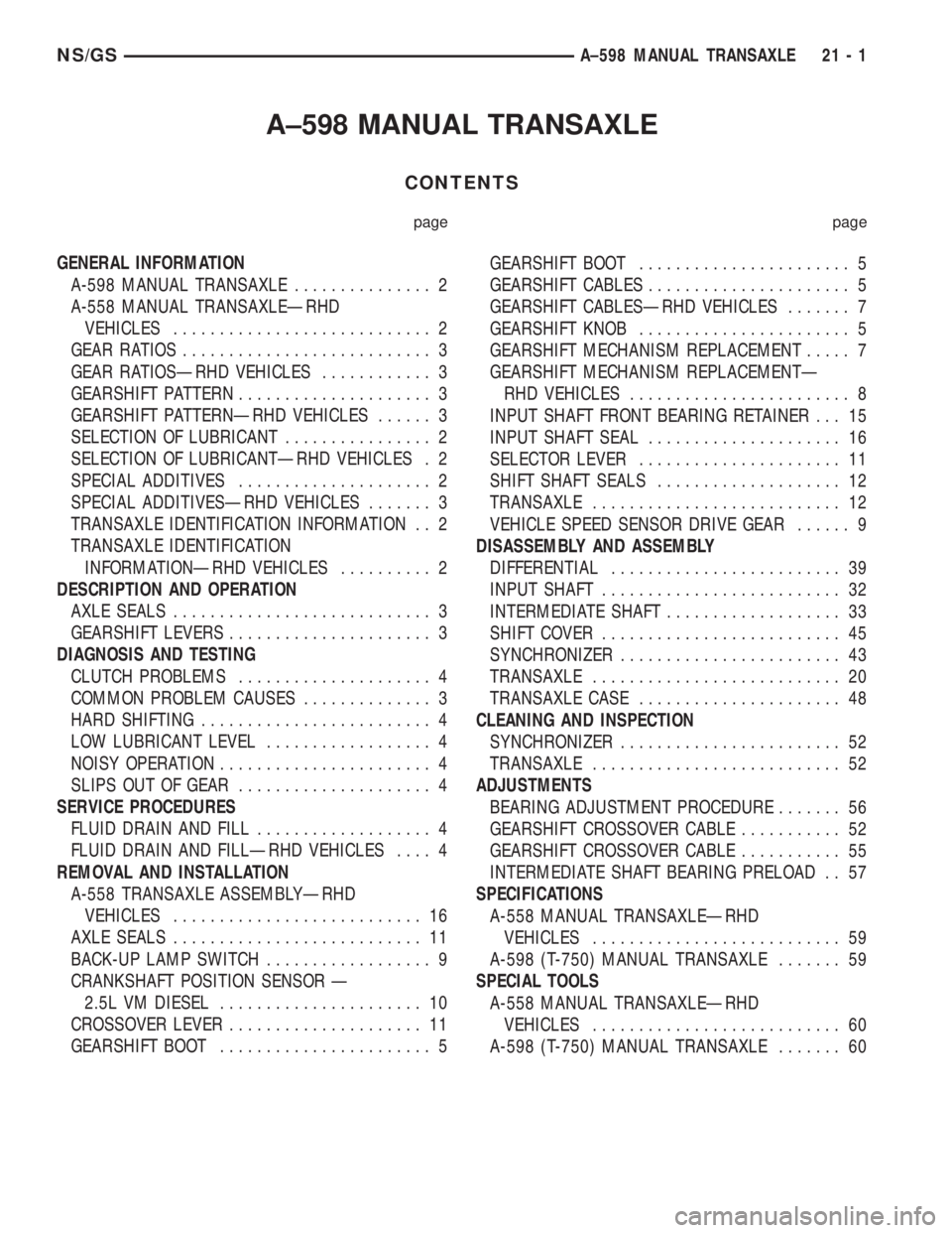
A±598 MANUAL TRANSAXLE
CONTENTS
page page
GENERAL INFORMATION
A-598 MANUAL TRANSAXLE............... 2
A-558 MANUAL TRANSAXLEÐRHD
VEHICLES............................ 2
GEAR RATIOS........................... 3
GEAR RATIOSÐRHD VEHICLES............ 3
GEARSHIFT PATTERN..................... 3
GEARSHIFT PATTERNÐRHD VEHICLES...... 3
SELECTION OF LUBRICANT................ 2
SELECTION OF LUBRICANTÐRHD VEHICLES . 2
SPECIAL ADDITIVES..................... 2
SPECIAL ADDITIVESÐRHD VEHICLES....... 3
TRANSAXLE IDENTIFICATION INFORMATION . . 2
TRANSAXLE IDENTIFICATION
INFORMATIONÐRHD VEHICLES.......... 2
DESCRIPTION AND OPERATION
AXLE SEALS............................ 3
GEARSHIFT LEVERS...................... 3
DIAGNOSIS AND TESTING
CLUTCH PROBLEMS..................... 4
COMMON PROBLEM CAUSES.............. 3
HARD SHIFTING......................... 4
LOW LUBRICANT LEVEL.................. 4
NOISY OPERATION....................... 4
SLIPS OUT OF GEAR..................... 4
SERVICE PROCEDURES
FLUID DRAIN AND FILL................... 4
FLUID DRAIN AND FILLÐRHD VEHICLES.... 4
REMOVAL AND INSTALLATION
A-558 TRANSAXLE ASSEMBLYÐRHD
VEHICLES........................... 16
AXLE SEALS........................... 11
BACK-UP LAMP SWITCH.................. 9
CRANKSHAFT POSITION SENSOR Ð
2.5L VM DIESEL...................... 10
CROSSOVER LEVER..................... 11
GEARSHIFT BOOT....................... 5GEARSHIFT BOOT....................... 5
GEARSHIFT CABLES...................... 5
GEARSHIFT CABLESÐRHD VEHICLES....... 7
GEARSHIFT KNOB....................... 5
GEARSHIFT MECHANISM REPLACEMENT..... 7
GEARSHIFT MECHANISM REPLACEMENTÐ
RHD VEHICLES........................ 8
INPUT SHAFT FRONT BEARING RETAINER . . . 15
INPUT SHAFT SEAL..................... 16
SELECTOR LEVER...................... 11
SHIFT SHAFT SEALS.................... 12
TRANSAXLE........................... 12
VEHICLE SPEED SENSOR DRIVE GEAR...... 9
DISASSEMBLY AND ASSEMBLY
DIFFERENTIAL......................... 39
INPUT SHAFT.......................... 32
INTERMEDIATE SHAFT................... 33
SHIFT COVER.......................... 45
SYNCHRONIZER........................ 43
TRANSAXLE........................... 20
TRANSAXLE CASE...................... 48
CLEANING AND INSPECTION
SYNCHRONIZER........................ 52
TRANSAXLE........................... 52
ADJUSTMENTS
BEARING ADJUSTMENT PROCEDURE....... 56
GEARSHIFT CROSSOVER CABLE........... 52
GEARSHIFT CROSSOVER CABLE........... 55
INTERMEDIATE SHAFT BEARING PRELOAD . . 57
SPECIFICATIONS
A-558 MANUAL TRANSAXLEÐRHD
VEHICLES........................... 59
A-598 (T-750) MANUAL TRANSAXLE....... 59
SPECIAL TOOLS
A-558 MANUAL TRANSAXLEÐRHD
VEHICLES........................... 60
A-598 (T-750) MANUAL TRANSAXLE....... 60
NS/GSA±598 MANUAL TRANSAXLE 21 - 1
Page 1658 of 1938
GENERAL INFORMATION
A-598 MANUAL TRANSAXLE
Safety goggles should be worn at all times
when working on these transaxles.The A-598
manual transaxle uses SAE 5W-30 engine oil, meet-
ing SG and/or SG-CD qualifications, as the factory
fill lubricant. SAE G5 10W-40 engine oil is a suitable
service fill alternative.
This transaxle combines gear reduction, ratio selec-
tion, and differential functions in one unit. It is
housed in a die-cast aluminum case.
A-558 MANUAL TRANSAXLEÐRHD VEHICLES
Safety goggles should be worn at all times
when working on these transaxles.The A-558
manual transaxle uses SAE 5W-30 engine oil, meet-
ing SG and/or SG-CD qualifications, as the factory
fill lubricant. SAE G5 10W-40 engine oil is a suitable
service fill alternative.
This transaxle combines gear reduction, ratio selec-
tion, and differential functions in one unit. It is
housed in a die-cast aluminum case.
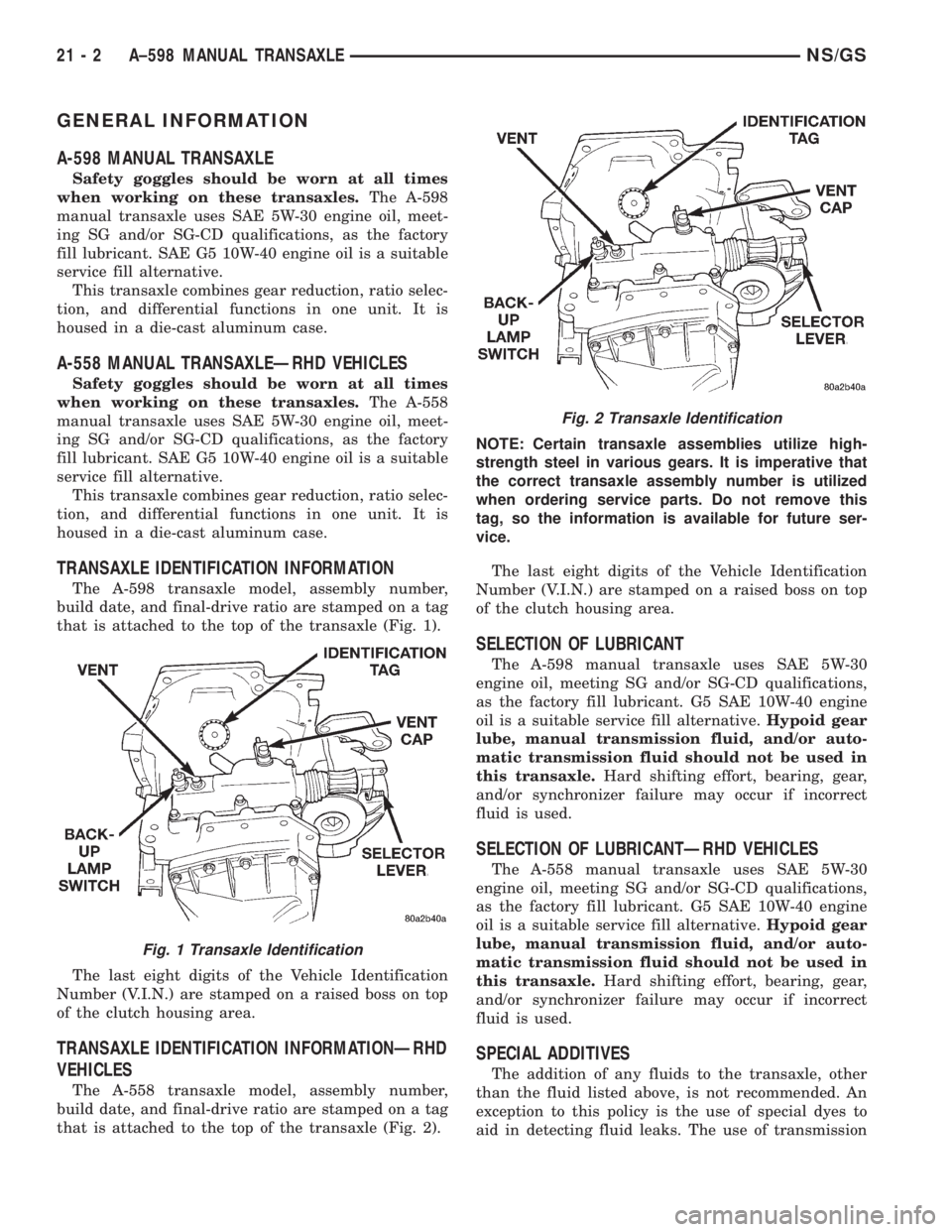
TRANSAXLE IDENTIFICATION INFORMATION
The A-598 transaxle model, assembly number,
build date, and final-drive ratio are stamped on a tag
that is attached to the top of the transaxle (Fig. 1).
The last eight digits of the Vehicle Identification
Number (V.I.N.) are stamped on a raised boss on top
of the clutch housing area.
TRANSAXLE IDENTIFICATION INFORMATIONÐRHD
VEHICLES
The A-558 transaxle model, assembly number,
build date, and final-drive ratio are stamped on a tag
that is attached to the top of the transaxle (Fig. 2).NOTE: Certain transaxle assemblies utilize high-
strength steel in various gears. It is imperative that
the correct transaxle assembly number is utilized
when ordering service parts. Do not remove this
tag, so the information is available for future ser-
vice.
The last eight digits of the Vehicle Identification
Number (V.I.N.) are stamped on a raised boss on top
of the clutch housing area.
SELECTION OF LUBRICANT
The A-598 manual transaxle uses SAE 5W-30
engine oil, meeting SG and/or SG-CD qualifications,
as the factory fill lubricant. G5 SAE 10W-40 engine
oil is a suitable service fill alternative.Hypoid gear
lube, manual transmission fluid, and/or auto-
matic transmission fluid should not be used in
this transaxle.Hard shifting effort, bearing, gear,
and/or synchronizer failure may occur if incorrect
fluid is used.
SELECTION OF LUBRICANTÐRHD VEHICLES
The A-558 manual transaxle uses SAE 5W-30
engine oil, meeting SG and/or SG-CD qualifications,
as the factory fill lubricant. G5 SAE 10W-40 engine
oil is a suitable service fill alternative.Hypoid gear
lube, manual transmission fluid, and/or auto-
matic transmission fluid should not be used in
this transaxle.Hard shifting effort, bearing, gear,
and/or synchronizer failure may occur if incorrect
fluid is used.
SPECIAL ADDITIVES
The addition of any fluids to the transaxle, other
than the fluid listed above, is not recommended. An
exception to this policy is the use of special dyes to
aid in detecting fluid leaks. The use of transmission
Fig. 1 Transaxle Identification
Fig. 2 Transaxle Identification
21 - 2 A±598 MANUAL TRANSAXLENS/GS