1996 CHRYSLER VOYAGER clutch
[x] Cancel search: clutchPage 1828 of 1938
probe will drop the temperature 7ÉC (20ÉF) in two
minutes. If the Evaporator Probe is found to be
faulty, check that the sensor is positioned in the
evaporator fins properly. If not, correct and repeat
test. If OK, replace the evaporator probe.
Once the repairs are completed, repeat the Calibra-
tion Diagnostic and Cooldown test. Repeating the
test is necessary to clear the fault codes.
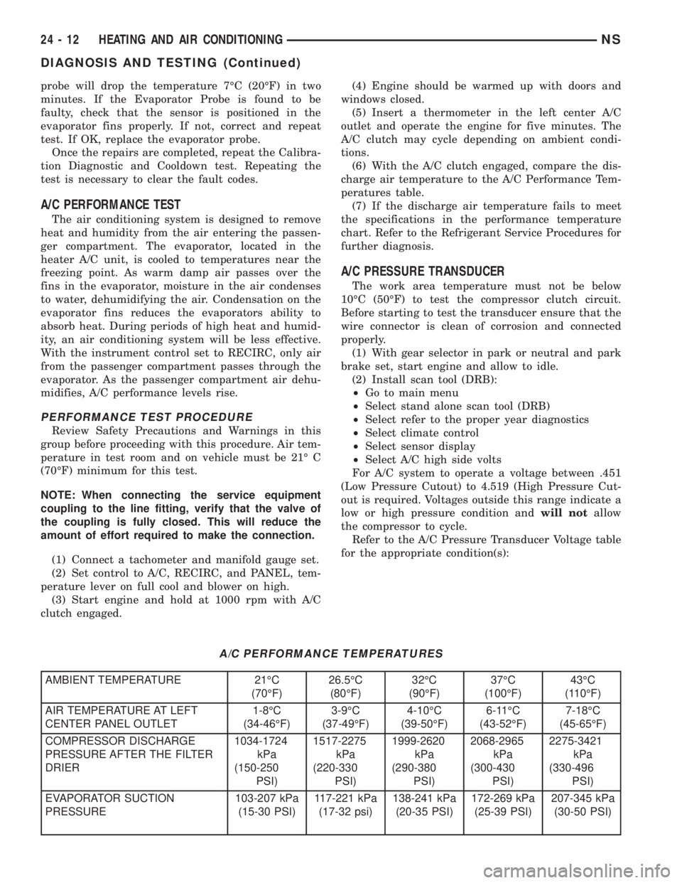
A/C PERFORMANCE TEST
The air conditioning system is designed to remove
heat and humidity from the air entering the passen-
ger compartment. The evaporator, located in the
heater A/C unit, is cooled to temperatures near the
freezing point. As warm damp air passes over the
fins in the evaporator, moisture in the air condenses
to water, dehumidifying the air. Condensation on the
evaporator fins reduces the evaporators ability to
absorb heat. During periods of high heat and humid-
ity, an air conditioning system will be less effective.
With the instrument control set to RECIRC, only air
from the passenger compartment passes through the
evaporator. As the passenger compartment air dehu-
midifies, A/C performance levels rise.
PERFORMANCE TEST PROCEDURE
Review Safety Precautions and Warnings in this
group before proceeding with this procedure. Air tem-
perature in test room and on vehicle must be 21É C
(70ÉF) minimum for this test.
NOTE: When connecting the service equipment
coupling to the line fitting, verify that the valve of
the coupling is fully closed. This will reduce the
amount of effort required to make the connection.
(1) Connect a tachometer and manifold gauge set.
(2) Set control to A/C, RECIRC, and PANEL, tem-
perature lever on full cool and blower on high.
(3) Start engine and hold at 1000 rpm with A/C
clutch engaged.(4) Engine should be warmed up with doors and
windows closed.
(5) Insert a thermometer in the left center A/C
outlet and operate the engine for five minutes. The
A/C clutch may cycle depending on ambient condi-
tions.
(6) With the A/C clutch engaged, compare the dis-
charge air temperature to the A/C Performance Tem-
peratures table.
(7) If the discharge air temperature fails to meet
the specifications in the performance temperature
chart. Refer to the Refrigerant Service Procedures for
further diagnosis.
A/C PRESSURE TRANSDUCER
The work area temperature must not be below
10ÉC (50ÉF) to test the compressor clutch circuit.
Before starting to test the transducer ensure that the
wire connector is clean of corrosion and connected
properly.
(1) With gear selector in park or neutral and park
brake set, start engine and allow to idle.
(2) Install scan tool (DRB):
²Go to main menu
²Select stand alone scan tool (DRB)
²Select refer to the proper year diagnostics
²Select climate control
²Select sensor display
²Select A/C high side volts
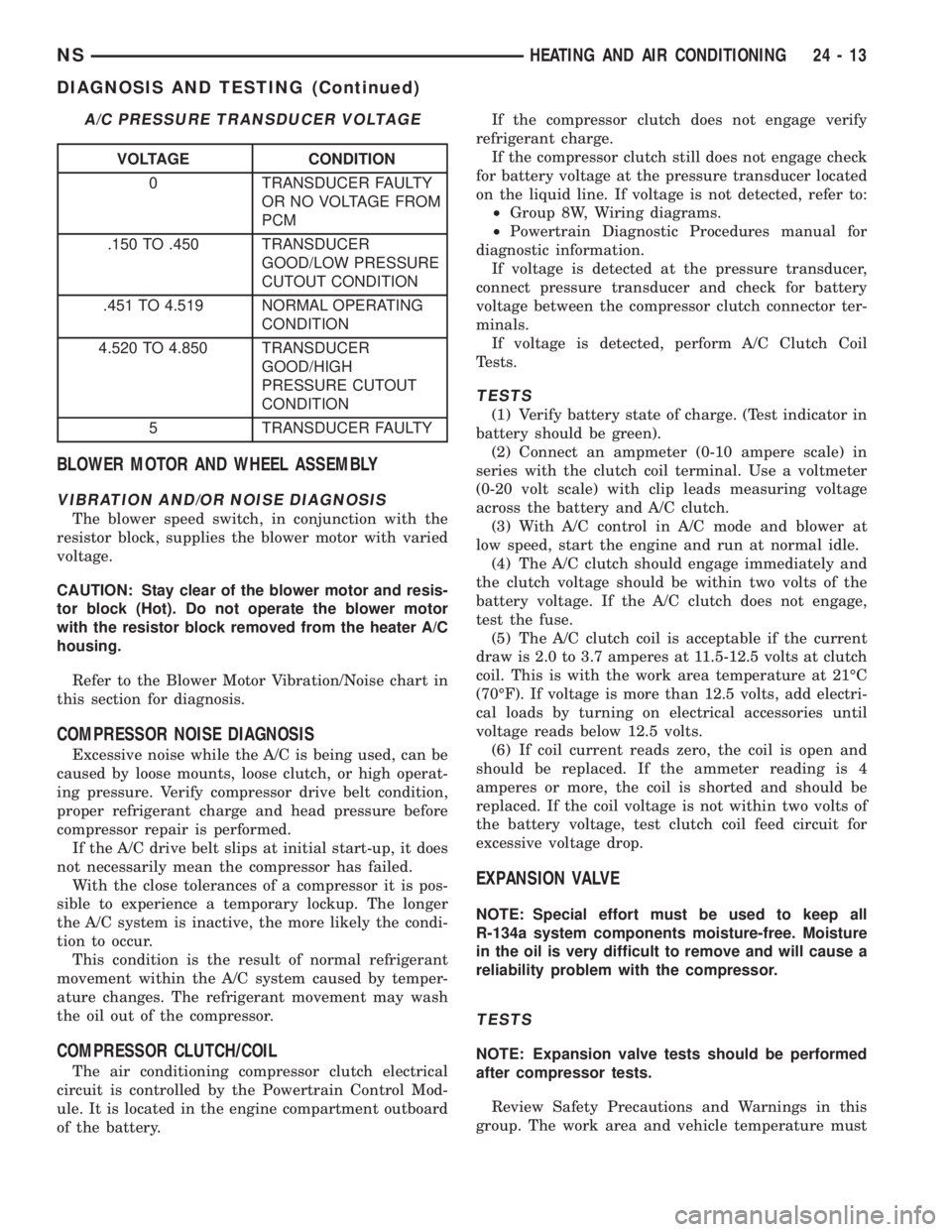
For A/C system to operate a voltage between .451
(Low Pressure Cutout) to 4.519 (High Pressure Cut-
out is required. Voltages outside this range indicate a
low or high pressure condition andwill notallow
the compressor to cycle.
Refer to the A/C Pressure Transducer Voltage table
for the appropriate condition(s):
A/C PERFORMANCE TEMPERATURES
AMBIENT TEMPERATURE 21ÉC
(70ÉF)26.5ÉC
(80ÉF)32ÉC
(90ÉF)37ÉC
(100ÉF)43ÉC
(110ÉF)
AIR TEMPERATURE AT LEFT
CENTER PANEL OUTLET1-8ÉC
(34-46ÉF)3-9ÉC
(37-49ÉF)4-10ÉC
(39-50ÉF)6-11ÉC
(43-52ÉF)7-18ÉC
(45-65ÉF)
COMPRESSOR DISCHARGE
PRESSURE AFTER THE FILTER
DRIER1034-1724
kPa
(150-250
PSI)1517-2275
kPa
(220-330
PSI)1999-2620
kPa
(290-380
PSI)2068-2965
kPa
(300-430
PSI)2275-3421
kPa
(330-496
PSI)
EVAPORATOR SUCTION
PRESSURE103-207 kPa
(15-30 PSI)117-221 kPa
(17-32 psi)138-241 kPa
(20-35 PSI)172-269 kPa
(25-39 PSI)207-345 kPa
(30-50 PSI)
24 - 12 HEATING AND AIR CONDITIONINGNS
DIAGNOSIS AND TESTING (Continued)
Page 1829 of 1938
BLOWER MOTOR AND WHEEL ASSEMBLY
VIBRATION AND/OR NOISE DIAGNOSIS
The blower speed switch, in conjunction with the
resistor block, supplies the blower motor with varied
voltage.
CAUTION: Stay clear of the blower motor and resis-
tor block (Hot). Do not operate the blower motor
with the resistor block removed from the heater A/C
housing.
Refer to the Blower Motor Vibration/Noise chart in
this section for diagnosis.
COMPRESSOR NOISE DIAGNOSIS
Excessive noise while the A/C is being used, can be
caused by loose mounts, loose clutch, or high operat-
ing pressure. Verify compressor drive belt condition,
proper refrigerant charge and head pressure before
compressor repair is performed.
If the A/C drive belt slips at initial start-up, it does
not necessarily mean the compressor has failed.
With the close tolerances of a compressor it is pos-
sible to experience a temporary lockup. The longer
the A/C system is inactive, the more likely the condi-
tion to occur.
This condition is the result of normal refrigerant
movement within the A/C system caused by temper-
ature changes. The refrigerant movement may wash
the oil out of the compressor.
COMPRESSOR CLUTCH/COIL
The air conditioning compressor clutch electrical
circuit is controlled by the Powertrain Control Mod-
ule. It is located in the engine compartment outboard
of the battery.If the compressor clutch does not engage verify
refrigerant charge.
If the compressor clutch still does not engage check
for battery voltage at the pressure transducer located
on the liquid line. If voltage is not detected, refer to:
²Group 8W, Wiring diagrams.
²Powertrain Diagnostic Procedures manual for
diagnostic information.
If voltage is detected at the pressure transducer,
connect pressure transducer and check for battery
voltage between the compressor clutch connector ter-
minals.
If voltage is detected, perform A/C Clutch Coil
Tests.
TESTS
(1) Verify battery state of charge. (Test indicator in
battery should be green).
(2) Connect an ampmeter (0-10 ampere scale) in
series with the clutch coil terminal. Use a voltmeter
(0-20 volt scale) with clip leads measuring voltage
across the battery and A/C clutch.
(3) With A/C control in A/C mode and blower at
low speed, start the engine and run at normal idle.
(4) The A/C clutch should engage immediately and
the clutch voltage should be within two volts of the
battery voltage. If the A/C clutch does not engage,
test the fuse.
(5) The A/C clutch coil is acceptable if the current
draw is 2.0 to 3.7 amperes at 11.5-12.5 volts at clutch
coil. This is with the work area temperature at 21ÉC
(70ÉF). If voltage is more than 12.5 volts, add electri-
cal loads by turning on electrical accessories until
voltage reads below 12.5 volts.
(6) If coil current reads zero, the coil is open and
should be replaced. If the ammeter reading is 4
amperes or more, the coil is shorted and should be
replaced. If the coil voltage is not within two volts of
the battery voltage, test clutch coil feed circuit for
excessive voltage drop.
EXPANSION VALVE
NOTE: Special effort must be used to keep all
R-134a system components moisture-free. Moisture
in the oil is very difficult to remove and will cause a
reliability problem with the compressor.
TESTS
NOTE: Expansion valve tests should be performed
after compressor tests.
Review Safety Precautions and Warnings in this
group. The work area and vehicle temperature must
A/C PRESSURE TRANSDUCER VOLTAGE
VOLTAGE CONDITION
0 TRANSDUCER FAULTY
OR NO VOLTAGE FROM
PCM
.150 TO .450 TRANSDUCER
GOOD/LOW PRESSURE
CUTOUT CONDITION
.451 TO 4.519 NORMAL OPERATING
CONDITION
4.520 TO 4.850 TRANSDUCER
GOOD/HIGH
PRESSURE CUTOUT
CONDITION
5 TRANSDUCER FAULTY
NSHEATING AND AIR CONDITIONING 24 - 13
DIAGNOSIS AND TESTING (Continued)
Page 1834 of 1938
NOTE: When connecting the service equipment
coupling to the line fitting, verify that the valve of
the coupling is fully closed. This will reduce the
amount of effort required to make the connection.
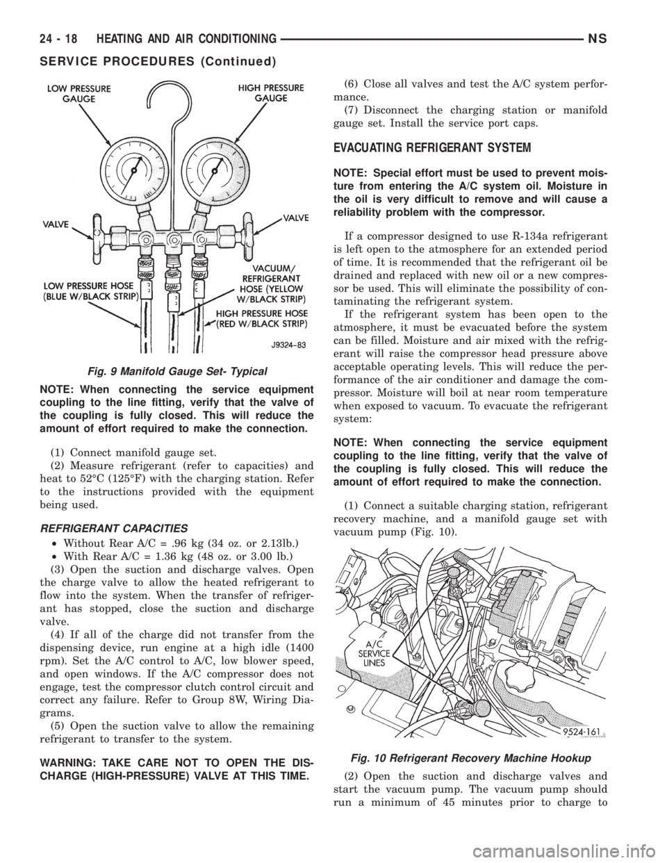
(1) Connect manifold gauge set.
(2) Measure refrigerant (refer to capacities) and
heat to 52ÉC (125ÉF) with the charging station. Refer
to the instructions provided with the equipment
being used.
REFRIGERANT CAPACITIES
²Without Rear A/C = .96 kg (34 oz. or 2.13lb.)
²With Rear A/C = 1.36 kg (48 oz. or 3.00 lb.)
(3) Open the suction and discharge valves. Open
the charge valve to allow the heated refrigerant to
flow into the system. When the transfer of refriger-
ant has stopped, close the suction and discharge
valve.
(4) If all of the charge did not transfer from the
dispensing device, run engine at a high idle (1400
rpm). Set the A/C control to A/C, low blower speed,
and open windows. If the A/C compressor does not
engage, test the compressor clutch control circuit and
correct any failure. Refer to Group 8W, Wiring Dia-
grams.
(5) Open the suction valve to allow the remaining
refrigerant to transfer to the system.
WARNING: TAKE CARE NOT TO OPEN THE DIS-
CHARGE (HIGH-PRESSURE) VALVE AT THIS TIME.(6) Close all valves and test the A/C system perfor-
mance.
(7) Disconnect the charging station or manifold
gauge set. Install the service port caps.
EVACUATING REFRIGERANT SYSTEM
NOTE: Special effort must be used to prevent mois-
ture from entering the A/C system oil. Moisture in
the oil is very difficult to remove and will cause a
reliability problem with the compressor.
If a compressor designed to use R-134a refrigerant
is left open to the atmosphere for an extended period
of time. It is recommended that the refrigerant oil be
drained and replaced with new oil or a new compres-
sor be used. This will eliminate the possibility of con-
taminating the refrigerant system.
If the refrigerant system has been open to the
atmosphere, it must be evacuated before the system
can be filled. Moisture and air mixed with the refrig-
erant will raise the compressor head pressure above
acceptable operating levels. This will reduce the per-
formance of the air conditioner and damage the com-
pressor. Moisture will boil at near room temperature
when exposed to vacuum. To evacuate the refrigerant
system:
NOTE: When connecting the service equipment
coupling to the line fitting, verify that the valve of
the coupling is fully closed. This will reduce the
amount of effort required to make the connection.
(1) Connect a suitable charging station, refrigerant
recovery machine, and a manifold gauge set with
vacuum pump (Fig. 10).
(2) Open the suction and discharge valves and
start the vacuum pump. The vacuum pump should
run a minimum of 45 minutes prior to charge to
Fig. 9 Manifold Gauge Set- Typical
Fig. 10 Refrigerant Recovery Machine Hookup
24 - 18 HEATING AND AIR CONDITIONINGNS
SERVICE PROCEDURES (Continued)
Page 1839 of 1938
COMPRESSOR
REMOVAL
WARNING: REFER TO REFRIGERANT SERVICE
PROCEDURES FOR INFORMATION REGARDING
PROPER RECOVERY OF THE REFRIGERANT
BEFORE ATTEMPTING TO REMOVE THE COM-
PRESSOR.
(1) Disconnect negative battery cable.
(2) Pinch off coolant lines to rear Heat unit (if
equipped). Drain engine coolant.
(3) Remove upper radiator hose.
(4) Remove drive belt (refer to Group 7, Cooling
System). Disconnect compressor clutch wire lead.
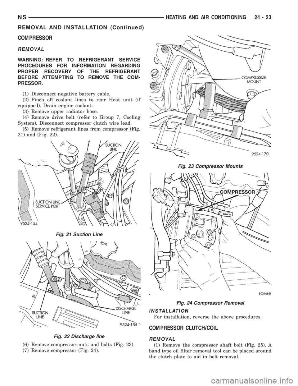
(5) Remove refrigerant lines from compressor (Fig.
21) and (Fig. 22).
(6) Remove compressor nuts and bolts (Fig. 23).
(7) Remove compressor (Fig. 24).
INSTALLATION
For installation, reverse the above procedures.
COMPRESSOR CLUTCH/COIL
REMOVAL
(1) Remove the compressor shaft bolt (Fig. 25). A
band type oil filter removal tool can be placed around
the clutch plate to aid in bolt removal.
Fig. 21 Suction Line
Fig. 22 Discharge line
Fig. 23 Compressor Mounts
Fig. 24 Compressor Removal
NSHEATING AND AIR CONDITIONING 24 - 23
REMOVAL AND INSTALLATION (Continued)
Page 1840 of 1938
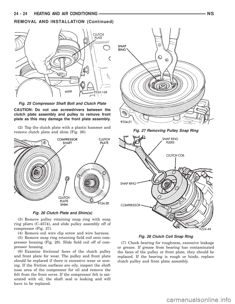
CAUTION: Do not use screwdrivers between the
clutch plate assembly and pulley to remove front
plate as this may damage the front plate assembly.
(2) Tap the clutch plate with a plastic hammer and
remove clutch plate and shim (Fig. 26).
(3) Remove pulley retaining snap ring with snap
ring pliers (C-4574), and slide pulley assembly off of
compressor (Fig. 27).
(4) Remove coil wire clip screw and wire harness.
(5) Remove snap ring retaining field coil onto com-
pressor housing (Fig. 28). Slide field coil off of com-
pressor housing.
(6) Examine frictional faces of the clutch pulley
and front plate for wear. The pulley and front plate
should be replaced if there is excessive wear or scor-
ing. If the friction surfaces are oily, inspect the shaft
nose area of the compressor for oil and remove the
felt from the front cover. If the compressor felt is sat-
urated with oil, the shaft seal is leaking and will
have to be replaced.(7) Check bearing for roughness, excessive leakage
or grease. If grease from bearing has contaminated
the faces of the pulley or front plate, they should be
replaced. If the bearing is rough or binds, replace
clutch pulley and front plate assembly.
Fig. 25 Compressor Shaft Bolt and Clutch Plate
Fig. 26 Clutch Plate and Shim(s)
Fig. 27 Removing Pulley Snap Ring
Fig. 28 Clutch Coil Snap Ring
24 - 24 HEATING AND AIR CONDITIONINGNS
REMOVAL AND INSTALLATION (Continued)
Page 1841 of 1938
CAUTION: The clutch pulley and the front plate
were mated at the factory by a burnishing opera-
tion. No attempt should be made to separately
replace either part. This will result in clutch slip-
page due to insufficient contact area.
INSTALLATION
(1) Align pin in back of field coil with hole in com-
pressor end housing, and position field coil into place.
Make sure that lead wires are properly routed, and
fasten with the wire clip screw.
(2) Install field coil retaining snap ring with snap
ring pliers. The bevel side of the snap ring facing
outward. Also both snap ring eyelets must be to the
right or left of the pin on compressor. Press snap ring
to make sure it is properly seated in the groove.
CAUTION: If snap ring is not fully seated it will
vibrate out, resulting in a clutch failure and severe
damage to the front face of the compressor.
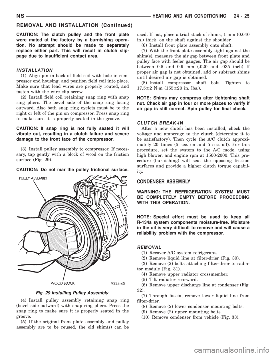
(3) Install pulley assembly to compressor. If neces-
sary, tap gently with a block of wood on the friction
surface (Fig. 29).
CAUTION: Do not mar the pulley frictional surface.
(4) Install pulley assembly retaining snap ring
(bevel side outward) with snap ring pliers. Press the
snap ring to make sure it is properly seated in the
groove.
(5) If the original front plate assembly and pulley
assembly are to be reused, the old shim(s) can beused. If not, place a trial stack of shims, 1 mm (0.040
in.) thick, on the shaft against the shoulder.
(6) Install front plate assembly onto shaft.
(7) With the front plate assembly tight against the
shim(s), measure the air gap between front plate and
pulley face with feeler gauges. The air gap should be
between 0.5 and 0.9 mm (.020 and .035 inch) If
proper air gap is not obtained, add or subtract shims
until desired air gap is obtained.
(8) Install compressor shaft bolt. Tighten to
17.562 N´m (155620 in. lbs.).
NOTE: Shims may compress after tightening shaft
nut. Check air gap in four or more places to verify if
air gap is still correct. Spin pulley for final check.
CLUTCH BREAK-IN
After a new clutch has been installed, check the
voltage and amperage to the clutch (determine it to
be satisfactory). Then cycle the A/C clutch approxi-
mately 20 times (5 sec. on and 5 sec. off). For this
procedure, set the system to the A/C mode, using
high blower, and engine rpm at 1500-2000. This pro-
cedure (burnishing) will seat the opposing friction
surfaces and provide a higher clutch torque capabil-
ity.
CONDENSER ASSEMBLY
WARNING: THE REFRIGERATION SYSTEM MUST
BE COMPLETELY EMPTY BEFORE PROCEEDING
WITH THIS OPERATION.
NOTE: Special effort must be used to keep all
R-134a system components moisture-free. Moisture
in the oil is very difficult to remove and will cause a
reliability problem with the compressor.
REMOVAL
(1) Recover A/C system refrigerant.
(2) Remove liquid line at filter-drier (Fig. 30).
(3) Remove (2) bolts attaching filter-drier to radia-
tor module (Fig. 31).
(4) Remove upper radiator crossmember.
(5) Tilt radiator rearward.
(6) Remove upper discharge line at condenser (Fig.
32).
(7) Through fascia, remove lower liquid line from
filter-drier.
(8) Remove (2) lower condenser mounting bolts.
(9) Remove (2) upper mounting bolts.
(10) Remove condenser from vehicle (Fig. 33).
Fig. 29 Installing Pulley Assembly
NSHEATING AND AIR CONDITIONING 24 - 25
REMOVAL AND INSTALLATION (Continued)
Page 1867 of 1938
HEATING AND AIR CONDITIONING
CONTENTS
page page
GENERAL INFORMATION
INTRODUCTION........................ 1
SAFETY PRECAUTIONS AND WARNINGS.... 2
DESCRIPTION AND OPERATION
A/C PRESSURE TRANSDUCER............ 2
A/C SERVICE PORTS.................... 2
AIR DISTRIBUTION DUCTS............... 2
COMPRESSOR......................... 2
COMPRESSOR HIGH-PRESSURE RELIEF
VALVE .............................. 3
CONDENSATE DRAIN.................... 3
ENGINE COOLING SYSTEM REQUIREMENTS . 3
EVAPORATOR PROBE................... 3
HANDLING TUBING AND FITTINGS........ 3
HVAC CONTROL MODULE................ 3
SIDE DOOR HEATER A/C OUTLETS........ 4
SIDE WINDOW DEMISTER............... 4
SYSTEM AIRFLOW..................... 4
SYSTEM OIL LEVEL..................... 4
DIAGNOSIS AND TESTING
A/C PERFORMANCE TEST............... 11
A/C PRESSURE TRANSDUCER........... 11
ACTUATOR CALIBRATION/DIAGNOSTICS AND
COOLDOWN TEST..................... 5
BLOWER MOTOR AND WHEEL ASSEMBLY . 12
COMPRESSOR CLUTCH/COIL............ 12
COMPRESSOR NOISE DIAGNOSIS........ 12
EXPANSION VALVE.................... 14
HEATER PERFORMANCE TEST........... 14
HVAC CONTROL DIAGNOSTIC CONDITIONS . 9
SYSTEM CHARGE LEVEL TEST........... 15SERVICE PROCEDURES
CHARGING REFRIGERANT SYSTEM....... 17
EVACUATING REFRIGERANT SYSTEM..... 17
R-134a REFRIGERANT.................. 16
STICKING HVAC CONTROL MODULE PUSH
BUTTONS.......................... 18
SYSTEM LEAK CHECKING............... 19
THERMOCOUPLE PROBE............... 18
REMOVAL AND INSTALLATION
A/C PRESSURE TRANSDUCER........... 19
A/C SERVICE PORTS................... 19
BLEND-AIR DOOR ACTUATOR........... 20
BLOWER MOTOR AND WHEEL ASSEMBLY . 20
BLOWER MOTOR RESISTOR BLOCK...... 21
BLOWER MOTOR WHEEL............... 22
COMPRESSOR (2.5L TURBO DIESEL)..... 22
CONDENSER ASSEMBLY................ 23
DISCHARGE LINE..................... 23
EVAPORATOR PROBE.................. 24
EXPANSION VALVE.................... 25
FILTER-DRIER ASSEMBLY............... 26
HEATER A/C UNIT HOUSING............. 26
HEATER CORE........................ 26
HEATER HOSES....................... 28
LIQUID LINE......................... 28
MODE DOOR ACTUATOR................ 29
RECIRC DOOR ACTUATOR.............. 30
SIDE WINDOW DEMISTER DUCTS........ 29
SUCTION LINE........................ 29
DISASSEMBLY AND ASSEMBLY
HEATER A/C UNIT RECONDITION......... 30
GENERAL INFORMATION
INTRODUCTION
The Heater, or Heater and Air Conditioning sys-
tems share many of the same components. This
group will deal with both systems together when
component function is common, and separately when
they are not.
For proper operation of the instrument panel con-
trols, refer to the Owner's Manual provided with the
vehicle.All vehicles are equipped with a common Heater
A/C unit housing assembly. When the vehicle has
only a heater system, the evaporator and recirculat-
ing air door are omitted.
An optional zone control HVAC unit is available.
This unit has dual blend-air doors that can be regu-
lated independently of each other. The temperature
setting can be different from driver's side to passen-
ger side.
NS/GSHEATING AND AIR CONDITIONING 24 - 1
Page 1868 of 1938
SAFETY PRECAUTIONS AND WARNINGS
WARNING: WEAR EYE PROTECTION WHEN SER-
VICING THE AIR CONDITIONING REFRIGERANT
SYSTEM. SERIOUS EYE INJURY CAN RESULT
FROM EYE CONTACT WITH REFRIGERANT. IF EYE
CONTACT IS MADE, SEEK MEDICAL ATTENTION
IMMEDIATELY.
DO NOT EXPOSE REFRIGERANT TO OPEN
FLAME. POISONOUS GAS IS CREATED WHEN
REFRIGERANT IS BURNED. AN ELECTRONIC TYPE
LEAK DETECTOR IS RECOMMENDED.
LARGE AMOUNTS OF REFRIGERANT RELEASED
IN A CLOSED WORK AREA WILL DISPLACE THE
OXYGEN AND CAUSE SUFFOCATION.
THE EVAPORATION RATE OF REFRIGERANT AT
AVERAGE TEMPERATURE AND ALTITUDE IS
EXTREMELY HIGH. AS A RESULT, ANYTHING THAT
COMES IN CONTACT WITH THE REFRIGERANT
WILL FREEZE. ALWAYS PROTECT SKIN OR DELI-
CATE OBJECTS FROM DIRECT CONTACT WITH
REFRIGERANT. R-134a SERVICE EQUIPMENT OR
VEHICLE A/C SYSTEM SHOULD NOT BE PRES-
SURE TESTED OR LEAK TESTED WITH COM-
PRESSED AIR.
SOME MIXTURES OF AIR and R-134a HAVE BEEN
SHOWN TO BE COMBUSTIBLE AT ELEVATED
PRESSURES. THESE MIXTURES ARE POTENTIALLY
DANGEROUS AND MAY RESULT IN FIRE OR
EXPLOSION CAUSING INJURY OR PROPERTY
DAMAGE.
ANTIFREEZE IS AN ETHYLENE GLYCOL BASE
COOLANT AND IS HARMFUL IF SWALLOWED OR
INHALED. SEEK MEDICAL ATTENTION IMMEDI-
ATELY IF SWALLOWED OR INHALED. DO NOT
STORE IN OPEN OR UNMARKED CONTAINERS.
WASH SKIN AND CLOTHING THOROUGHLY AFTER
COMING IN CONTACT WITH ETHYLENE GLYCOL.
KEEP OUT OF REACH OF CHILDREN AND PETS.
DO NOT OPEN A COOLING SYSTEM WHEN THE
ENGINE IS AT RUNNING TEMPERATURE. PER-
SONAL INJURY CAN RESULT.
CAUTION: The engine cooling system is designed
to develop internal pressure of 97 to 123 kPa (14 to
18 psi). Allow the vehicle to cool a minimum of 15
minutes before opening the cooling system. Refer
to Group 7, Cooling System.
DESCRIPTION AND OPERATION
AIR DISTRIBUTION DUCTS
The air distribution ducts for the A/C, Heater,
Defroster, and Second Seating Air Distribution arenot serviceable in vehicle. The procedures for service
of these ducts are covered in Group 8E, Instrument
Panel and Gauges.
The only ducts that are serviceable in the vehicle
are the side window demister ducts and the ducts
that feed the front door outlets for the first rear pas-
senger(s) seating. To service the door ducts refer to
Group 23, Body.
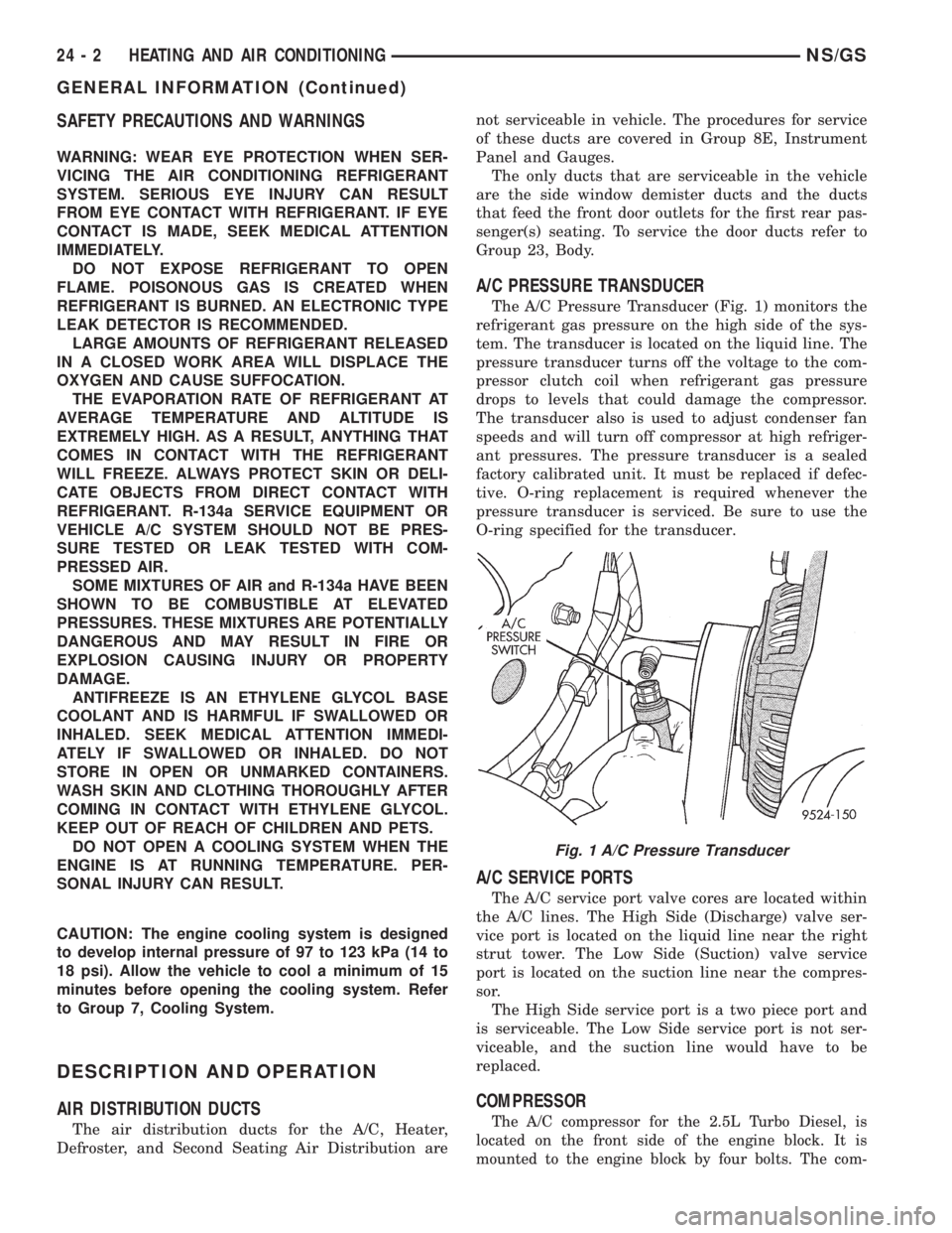
A/C PRESSURE TRANSDUCER
The A/C Pressure Transducer (Fig. 1) monitors the
refrigerant gas pressure on the high side of the sys-
tem. The transducer is located on the liquid line. The
pressure transducer turns off the voltage to the com-
pressor clutch coil when refrigerant gas pressure
drops to levels that could damage the compressor.
The transducer also is used to adjust condenser fan
speeds and will turn off compressor at high refriger-
ant pressures. The pressure transducer is a sealed
factory calibrated unit. It must be replaced if defec-
tive. O-ring replacement is required whenever the
pressure transducer is serviced. Be sure to use the
O-ring specified for the transducer.
A/C SERVICE PORTS
The A/C service port valve cores are located within
the A/C lines. The High Side (Discharge) valve ser-
vice port is located on the liquid line near the right
strut tower. The Low Side (Suction) valve service
port is located on the suction line near the compres-
sor.
The High Side service port is a two piece port and
is serviceable. The Low Side service port is not ser-
viceable, and the suction line would have to be
replaced.
COMPRESSOR
The A/C compressor for the 2.5L Turbo Diesel, is
located on the front side of the engine block. It is
mounted to the engine block by four bolts. The com-
Fig. 1 A/C Pressure Transducer
24 - 2 HEATING AND AIR CONDITIONINGNS/GS
GENERAL INFORMATION (Continued)