1996 CHRYSLER VOYAGER clutch
[x] Cancel search: clutchPage 1689 of 1938
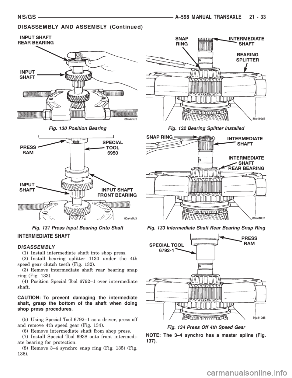
INTERMEDIATE SHAFT
DISASSEMBLY
(1) Install intermediate shaft into shop press.
(2) Install bearing splitter 1130 under the 4th
speed gear clutch teeth (Fig. 132).
(3) Remove intermediate shaft rear bearing snap
ring (Fig. 133).
(4) Position Special Tool 6792±1 over intermediate
shaft.
CAUTION: To prevent damaging the intermediate
shaft, grasp the bottom of the shaft when doing
shop press procedures.
(5) Using Special Tool 6792±1 as a driver, press off
and remove 4th speed gear (Fig. 134).
(6) Remove intermediate shaft from shop press.
(7) Install Special Tool 6938 onto front intermedi-
ate bearing for protection.
(8) Remove 3±4 synchro snap ring (Fig. 135) (Fig.
136).NOTE: The 3±4 synchro has a master spline (Fig.
137).
Fig. 130 Position Bearing
Fig. 131 Press Input Bearing Onto Shaft
Fig. 132 Bearing Splitter Installed
Fig. 133 Intermediate Shaft Rear Bearing Snap Ring
Fig. 134 Press Off 4th Speed Gear
NS/GSA±598 MANUAL TRANSAXLE 21 - 33
DISASSEMBLY AND ASSEMBLY (Continued)
Page 1705 of 1938
(2) Verify the oil feeder is centered within the
bearing bore.
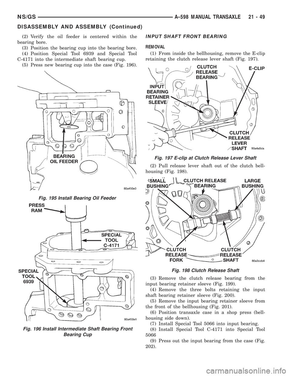
(3) Position the bearing cup into the bearing bore.
(4) Position Special Tool 6939 and Special Tool
C-4171 into the intermediate shaft bearing cup.
(5) Press new bearing cup into the case (Fig. 196).INPUT SHAFT FRONT BEARING
REMOVAL
(1) From inside the bellhousing, remove the E-clip
retaining the clutch release lever shaft (Fig. 197).
(2) Pull release lever shaft out of the clutch bell-
housing (Fig. 198).
(3) Remove the clutch release bearing from the
input bearing retainer sleeve (Fig. 199).
(4) Remove the three bolts retaining the input
shaft bearing retainer sleeve (Fig. 200).
(5) Remove the input bearing retainer sleeve from
the front of the bellhousing (Fig. 201).
(6) Position transaxle case in a shop press (bell-
housing side down).
(7) Install Special Tool 5066 into input bearing.
(8) Install Special Tool C-4171 into Special Tool
5066
(9) Press out the input bearing from the case (Fig.
202).
Fig. 196 Install Intermediate Shaft Bearing Front
Bearing Cup
Fig. 195 Install Bearing Oil Feeder
Fig. 197 E-clip at Clutch Release Lever Shaft
Fig. 198 Clutch Release Shaft
NS/GSA±598 MANUAL TRANSAXLE 21 - 49
DISASSEMBLY AND ASSEMBLY (Continued)
Page 1706 of 1938
INSTALLATION
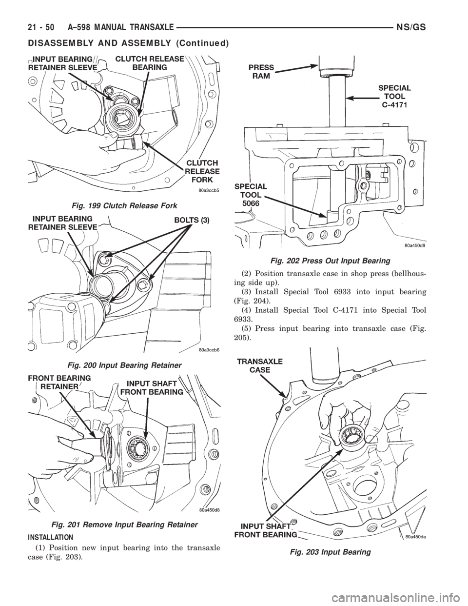
(1) Position new input bearing into the transaxle
case (Fig. 203).(2) Position transaxle case in shop press (bellhous-
ing side up).
(3) Install Special Tool 6933 into input bearing
(Fig. 204).
(4) Install Special Tool C-4171 into Special Tool
6933.
(5) Press input bearing into transaxle case (Fig.
205).
Fig. 199 Clutch Release Fork
Fig. 200 Input Bearing Retainer
Fig. 201 Remove Input Bearing Retainer
Fig. 202 Press Out Input Bearing
Fig. 203 Input Bearing
21 - 50 A±598 MANUAL TRANSAXLENS/GS
DISASSEMBLY AND ASSEMBLY (Continued)
Page 1707 of 1938
(6) Apply a small bead of Mopartgasket Maker to
the input bearing retainer.
(7) Install bearing retainer.
(8) Install clutch release fork onto clutch release
bearing.
(9) Install bearing and fork onto input bearing
retainer sleeve.
(10) Install clutch release shaft bushings into tran-
saxle case.
(11) Install clutch release shaft into case and
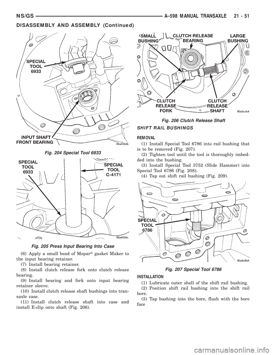
install E-clip onto shaft (Fig. 206).
SHIFT RAIL BUSHINGS
REMOVAL
(1) Install Special Tool 6786 into rail bushing that
is to be removed (Fig. 207).
(2) Tighten tool until the tool is thoroughly imbed-
ded into the bushing.
(3) Install Special Tool 3752 (Slide Hammer) into
Special Tool 6786 (Fig. 208).
(4) Tap out shift rail bushing (Fig. 209).
INSTALLATION
(1) Lubricate outer shell of the shift rail bushing.
(2) Position shift rail bushing into the shift rail
bore.
(3) Tap bushing into the bore, flush with the bore
face
Fig. 204 Special Tool 6933
Fig. 205 Press Input Bearing Into Case
Fig. 206 Clutch Release Shaft
Fig. 207 Special Tool 6786
NS/GSA±598 MANUAL TRANSAXLE 21 - 51
DISASSEMBLY AND ASSEMBLY (Continued)
Page 1715 of 1938
(14) Apply a bead of MopartGasket Maker or
equivalent onto bearing support plate. Install bearing
support plate.
(15) Install necessary shim calculated from Step
12
(16) Install bearing retainer plate. Tighten bearing
retainer plate to 17 N´m (250 in. lbs.).
(17) Install 5th drive gear onto the input shaft.
(18) Install 5th gear, synchro, fork, and plate.
(19) Install 5th gear synchro snap ring.
(20) Install 5th gear shift fork roll pin.
(21) Use Special Tool 6252 to hold 5th gear and
install new 5th gear nut at input shaft. Tighten the
retaining nut to 176 N´m (130 ft. lbs.).
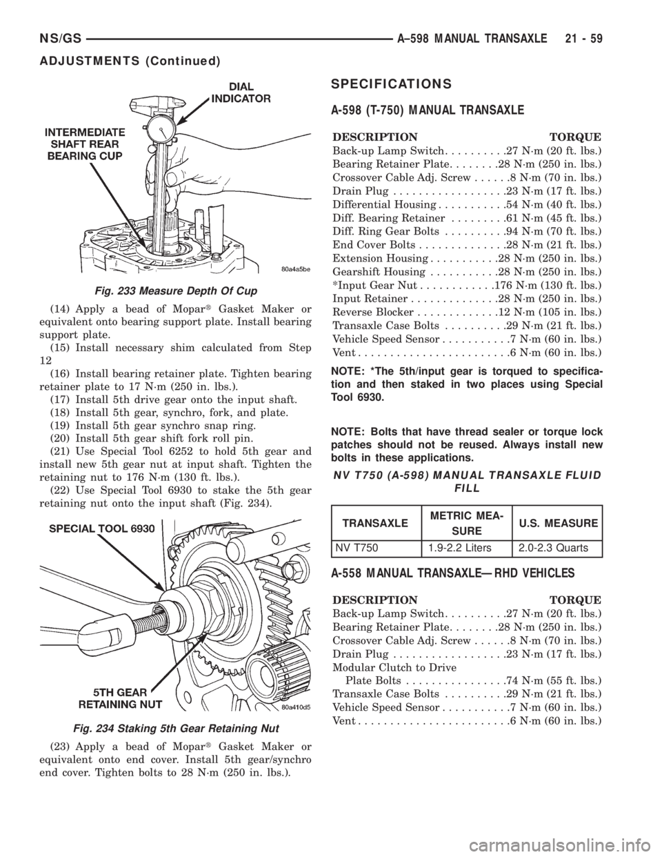
(22) Use Special Tool 6930 to stake the 5th gear
retaining nut onto the input shaft (Fig. 234).
(23) Apply a bead of MopartGasket Maker or
equivalent onto end cover. Install 5th gear/synchro
end cover. Tighten bolts to 28 N´m (250 in. lbs.).
SPECIFICATIONS
A-598 (T-750) MANUAL TRANSAXLE
DESCRIPTION TORQUE
Back-up Lamp Switch..........27N´m(20ft.lbs.)
Bearing Retainer Plate........28N´m(250 in. lbs.)
Crossover Cable Adj. Screw......8N´m(70in.lbs.)
Drain Plug..................23N´m(17ft.lbs.)
Differential Housing...........54N´m(40ft.lbs.)
Diff. Bearing Retainer.........61N´m(45ft.lbs.)
Diff. Ring Gear Bolts..........94N´m(70ft.lbs.)
End Cover Bolts..............28N´m(21ft.lbs.)
Extension Housing...........28N´m(250 in. lbs.)
Gearshift Housing...........28N´m(250 in. lbs.)
*Input Gear Nut............176 N´m (130 ft. lbs.)
Input Retainer..............28N´m(250 in. lbs.)
Reverse Blocker.............12N´m(105 in. lbs.)
Transaxle Case Bolts..........29N´m(21ft.lbs.)
Vehicle Speed Sensor...........7N´m(60in.lbs.)
Vent........................6N´m(60in.lbs.)
NOTE: *The 5th/input gear is torqued to specifica-
tion and then staked in two places using Special
Tool 6930.
NOTE: Bolts that have thread sealer or torque lock
patches should not be reused. Always install new
bolts in these applications.
A-558 MANUAL TRANSAXLEÐRHD VEHICLES
DESCRIPTION TORQUE
Back-up Lamp Switch..........27N´m(20ft.lbs.)
Bearing Retainer Plate........28N´m(250 in. lbs.)
Crossover Cable Adj. Screw......8N´m(70in.lbs.)
Drain Plug..................23N´m(17ft.lbs.)
Modular Clutch to Drive
Plate Bolts................74N´m(55ft.lbs.)
Transaxle Case Bolts..........29N´m(21ft.lbs.)
Vehicle Speed Sensor...........7N´m(60in.lbs.)
Vent........................6N´m(60in.lbs.)
Fig. 233 Measure Depth Of Cup
Fig. 234 Staking 5th Gear Retaining Nut
NV T750 (A-598) MANUAL TRANSAXLE FLUID
FILL
TRANSAXLEMETRIC MEA-
SUREU.S. MEASURE
NV T750 1.9-2.2 Liters 2.0-2.3 Quarts
NS/GSA±598 MANUAL TRANSAXLE 21 - 59
ADJUSTMENTS (Continued)
Page 1817 of 1938
HEATING AND AIR CONDITIONING
CONTENTS
page page
FRONT HEATING AND AIR CONDITIONING
SYSTEM............................... 1REAR HEATING AND AIR CONDITIONING
SYSTEM.............................. 41
FRONT HEATING AND AIR CONDITIONING SYSTEM
INDEX
page page
GENERAL INFORMATION
INTRODUCTION......................... 2
SAFETY PRECAUTIONS AND WARNINGS...... 2
DESCRIPTION AND OPERATION
A/C PRESSURE TRANSDUCER.............. 2
A/C SERVICE PORTS..................... 2
AIR DISTRIBUTION DUCTS................. 2
COMPRESSOR HIGH-PRESSURE RELIEF
VALVE................................ 3
CONDENSATE DRAIN..................... 3
ENGINE COOLING SYSTEM REQUIREMENTS . . 3
EVAPORATOR PROBE..................... 3
HANDLING TUBING AND FITTINGS........... 3
HVAC CONTROL MODULE................. 4
REAR BLOWER SPEED SWITCH............ 3
SIDE DOOR HEATER A/C OUTLETS.......... 4
SIDE WINDOW DEMISTER................. 4
SYSTEM AIRFLOW....................... 4
SYSTEM OIL LEVEL...................... 5
DIAGNOSIS AND TESTING
A/C PERFORMANCE TEST................ 12
A/C PRESSURE TRANSDUCER............. 12
ACTUATOR CALIBRATION/DIAGNOSTICS AND
COOLDOWN TEST...................... 6
BLOWER MOTOR AND WHEEL ASSEMBLY.... 13
COMPRESSOR CLUTCH/COIL.............. 13
COMPRESSOR NOISE DIAGNOSIS.......... 13
EXPANSION VALVE...................... 13
HEATER PERFORMANCE TEST............ 15
HVAC CONTROL DIAGNOSTIC CONDITIONS . . . 9
SYSTEM CHARGE LEVEL TEST............ 16SERVICE PROCEDURES
CHARGING REFRIGERANT SYSTEM........ 17
EVACUATING REFRIGERANT SYSTEM....... 18
R-134a REFRIGERANT................... 16
STICKING HVAC CONTROL MODULE PUSH
BUTTONS............................ 19
SYSTEM LEAK CHECKING................ 19
THERMOCOUPLE PROBE................. 19
REMOVAL AND INSTALLATION
A/C PRESSURE TRANSDUCER............. 20
A/C SERVICE PORTS.................... 20
BLEND-AIR DOOR ACTUATOR............. 20
BLOWER MOTOR AND WHEEL ASSEMBLY.... 21
BLOWER MOTOR RESISTOR BLOCK........ 21
BLOWER MOTOR WHEEL................. 22
COMPRESSOR CLUTCH/COIL.............. 23
COMPRESSOR......................... 23
CONDENSER ASSEMBLY................. 25
DISCHARGE LINE....................... 26
EVAPORATOR PROBE.................... 27
EXPANSION VALVE...................... 28
FILTER-DRIER ASSEMBLY................. 28
HEATER A/C UNIT HOUSING............... 29
HEATER CORE......................... 30
HEATER HOSES........................ 31
LIQUID LINE........................... 32
MODE DOOR ACTUATOR................. 32
RECIRC DOOR ACTUATOR................ 34
SIDE WINDOW DEMISTER DUCTS.......... 33
SUCTION LINE.......................... 33
DISASSEMBLY AND ASSEMBLY
HEATER A/C UNIT RECONDITION........... 34
NSHEATING AND AIR CONDITIONING 24 - 1
Page 1818 of 1938
GENERAL INFORMATION
INTRODUCTION
Both the heater and the heater/air conditioning
systems share many of the same components. This
group will deal with both systems together when
component function is common, and separately when
they are not.
For proper operation of the instrument panel con-
trols, refer to the Owner's Manual provided with the
vehicle.
All vehicles are equipped with a common A/C-
heater unit housing assembly. When the vehicle has
only a heater system, the evaporator and recirculat-
ing air door are omitted.
An optional zone control HVAC unit is available.
This unit has dual blend-air doors that can be regu-
lated independently of each other. The temperature
setting can be different from driver's side to passen-
ger side. There is also a rear (aux.) heating and A/C
system available when the vehicle is equipped with
zone control.
SAFETY PRECAUTIONS AND WARNINGS
WARNING: WEAR EYE PROTECTION WHEN SER-
VICING THE AIR CONDITIONING REFRIGERANT
SYSTEM. SERIOUS EYE INJURY CAN RESULT
FROM EYE CONTACT WITH REFRIGERANT. IF EYE
CONTACT IS MADE, SEEK MEDICAL ATTENTION
IMMEDIATELY.
DO NOT EXPOSE REFRIGERANT TO OPEN
FLAME. POISONOUS GAS IS CREATED WHEN
REFRIGERANT IS BURNED. AN ELECTRONIC TYPE
LEAK DETECTOR IS RECOMMENDED.
LARGE AMOUNTS OF REFRIGERANT RELEASED
IN A CLOSED WORK AREA WILL DISPLACE THE
OXYGEN AND CAUSE SUFFOCATION.
THE EVAPORATION RATE OF REFRIGERANT AT
AVERAGE TEMPERATURE AND ALTITUDE IS
EXTREMELY HIGH. AS A RESULT, ANYTHING THAT
COMES IN CONTACT WITH THE REFRIGERANT
WILL FREEZE. ALWAYS PROTECT SKIN OR DELI-
CATE OBJECTS FROM DIRECT CONTACT WITH
REFRIGERANT. R-134a SERVICE EQUIPMENT OR
VEHICLE A/C SYSTEM SHOULD NOT BE PRES-
SURE TESTED OR LEAK TESTED WITH COM-
PRESSED AIR.
SOME MIXTURES OF AIR and R-134a HAVE BEEN
SHOWN TO BE COMBUSTIBLE AT ELEVATED
PRESSURES. THESE MIXTURES ARE POTENTIALLY
DANGEROUS AND MAY RESULT IN FIRE OR
EXPLOSION CAUSING INJURY OR PROPERTY
DAMAGE.
ANTIFREEZE IS AN ETHYLENE GLYCOL BASE
COOLANT AND IS HARMFUL IF SWALLOWED ORINHALED. SEEK MEDICAL ATTENTION IMMEDI-
ATELY IF SWALLOWED OR INHALED. DO NOT
STORE IN OPEN OR UNMARKED CONTAINERS.
WASH SKIN AND CLOTHING THOROUGHLY AFTER
COMING IN CONTACT WITH ETHYLENE GLYCOL.
KEEP OUT OF REACH OF CHILDREN AND PETS.
DO NOT OPEN A COOLING SYSTEM WHEN THE
ENGINE IS AT RUNNING TEMPERATURE. PER-
SONAL INJURY CAN RESULT.
CAUTION: The engine cooling system is designed
to develop internal pressure of 97 to 123 kPa (14 to
18 psi). Allow the vehicle to cool a minimum of 15
minutes before opening the cooling system. Refer
to Group 7, Cooling System.
DESCRIPTION AND OPERATION
AIR DISTRIBUTION DUCTS
The air distribution ducts for the A/C, Heater,
Defroster, and Second Seating Air Distribution are
not serviceable in vehicle. The procedures for service
of these ducts are covered in Group 8E, Instrument
Panel and Gauges.
The only ducts that are serviceable in the vehicle
are the side window demister ducts and the ducts
that feed the front door outlets for the first rear pas-
senger(s) seating. To service the door ducts refer to
Group 23, Body.
A/C PRESSURE TRANSDUCER
The A/C Pressure Transducer (Fig. 1) monitors the
refrigerant gas pressure on the high side of the sys-
tem. The transducer is located on the liquid line. The
pressure transducer turns off the voltage to the com-
pressor clutch coil when refrigerant gas pressure
drops to levels that could damage the compressor.
The transducer also is used to adjust condenser fan
speeds and will turn off compressor at high refriger-
ant pressures. The pressure transducer is a sealed
factory calibrated unit. It must be replaced if defec-
tive. O-ring replacement is required whenever the
pressure transducer is serviced. Be sure to use the
O-ring specified for the transducer.
A/C SERVICE PORTS
The A/C service port valve cores are located within
the A/C lines (Fig. 2). The High Side (Discharge)
valve service port is located on the liquid line near
the right frame rail. The Low Side (Suction) valve
service port is located on the suction line near the
compressor.
24 - 2 HEATING AND AIR CONDITIONINGNS
Page 1825 of 1938
FAIL CODES/LEVEL DISPLAY
Fail Codes/Level are displayed using the REAR
WIPER and INTERMITTENT LED's flashing in the
sequence indicated below. The REAR WIPER LED
represents the Level and the INTERMITTENT LED
represents the Value. After Calibration/Diagnostics is
completed, the control will begin flashing Level 1
codes. Depressing the WASH button will cycle to
Level 2, depressing WASH again will cycle to Level 3.
Each time the WASH button is depressed will cycle
to the next level. After Level 5 is reached, you will
cycle back to Level 1. If the Control is a Heater Only
you will only cycle from Levels 1 to 3.
TEMPERATURE AND MODE POTENTIOMETER
DIAGNOSTICS
The Temperature and Mode Potentiometer can be
tested after calibration is complete by pressing the
WASH button and cycling to Levels 2, 3 or 5 as dis-
played by the REAR WIPER LED. On Heater Only
units you can only cycle to Levels 2 and 3. In eachindividual test the INTERMITTENT LED flash rate
will change as the Temperature or Mode potentiome-
ter is moved from one end to the other, see Potenti-
ometer vs. Position and Flash Rate table.
EVAPORATOR PROBE TEMPERATURE
DIAGNOSTICS
The evaporator probe can be tested by using the
INTERMITTENT LED to display the actual temper-
ature the sensor is reading. The HVAC control mod-
ule can only display temperatures from 1 to 99
degrees. To read the temperature, perform the follow-
ing:
²Set Blower motor to any speed other than OFF
²Set A/C to ON, if A/C Clutch does not engage
make sure Fail Codes 5 and 6 are cleared.To clear
the error code 5 and 6 the evaporator probe and/or
the wiring repair needs to be completed. Then, press
and hold the intermittent wipe button for 5 seconds.
²Run Diagnostics (Depress REAR WIPER and
REAR WASH)
²When Diagnostics is complete, Cycle to Level 4.
Display Sequence is as follows:
²REAR WIPER LED will display the Level
²INTERMITTENT LED will display ten's digit
²Short Pause
²INTERMITTENT LED will display the one's
digit.
The HVAC control module will continue to cycle
the Level and then Temperature until the level is
changed or Calibration Diagnostics and Cooldown
test is exited.
HVAC CONTROL DIAGNOSTIC CONDITIONS
For wiring circuits, wiring connectors, and Pin
numbers, refer to Group 8W, Wiring Diagrams.
After calibration, Rear Wiper LED flashing
once, Intermittent LED not flashing.
The system has passed calibration. Press the Rear
Wiper button to exit calibration.
WIPE BUTTON LED
LEVEL DISPLAY
1 FAIL CODES
2 MODE POTENTIOMETER TEST
3 BLEND/PASS. POTENTIOMETER TEST
4 EVAPORATOR PROBE (A/C AND ZONE
UNITS ONLY)
5 DRIVER POTENTIOMETER (ZONE UNITS
ONLY)
LEVEL 1±FAILURE CODE VALUES
(INTERMITTENT WIPE BUTTON LED)
CODE DEFINITION
0 PASSED ALL TESTS
1 MODE ACTUATOR DID NOT REACH
DEFROST POSITION
2 MODE ACTUATOR DID NOT REACH
PANEL POSITION
3 BLEND/PASS. ACTUATOR DID NOT
REACH COLD STOP
4 BLEND PASS. ACTUATOR DID NOT
REACH HEAT STOP
5 EVAPORATOR PROBE OPEN
6 EVAPORATOR PROBE SHORTED
7 DRIVER ACTUATOR DID NOT REACH
COLD STOP
8 ZONE/DRIVER ACTUATOR DID NOT
REACH HEAT STOP
9 CONTROL HEAD INTERNAL FAILURE
POTENTIOMETER VS. POSITION AND FLASH
RATE
POTENTIOM-
ETERINTERMIT-
TENT LED
FASTER
FLASH RATEINTERMITTENT
LED SLOWER
FLASH RATE
MODE PANEL DEFROST
BLEND/PASS. HOT COLD
DRIVER HOT COLD
NSHEATING AND AIR CONDITIONING 24 - 9
DIAGNOSIS AND TESTING (Continued)