1996 CHRYSLER VOYAGER clutch
[x] Cancel search: clutchPage 1660 of 1938
²Improper operation
HARD SHIFTING
Hard shifting may be caused by a misadjusted
crossover cable. If hard shifting is accompanied by
gear clash, synchronizer clutch and stop rings or gear
teeth may be worn or damaged.
Misassembled synchronizer components also cause
shifting problems. Incorrectly installed synchronizer
sleeves, struts, or springs can cause shift problems.
NOISY OPERATION
Transaxle noise is most often a result of worn or
damaged components. Chipped, broken gear or syn-
chronizer teeth, and brinnelled, spalled bearings all
cause noise.
Abnormal wear and damage to the internal compo-
nents is frequently the end result of insufficient
lubricant.
SLIPS OUT OF GEAR
Transaxle disengagement may be caused by mis-
aligned or damaged shift components, or worn teeth
on the drive gears or synchronizer components. Incor-
rect assembly also causes gear disengagement.
LOW LUBRICANT LEVEL
Insufficient transaxle lubricant is usually the
result of leaks, or inaccurate fluid level check or refill
method. Leakage is evident by the presence of oil
around the leak point. If leakage is not evident, the
condition is probably the result of an underfill.
If air±powered lubrication equipment is used to fill
a transaxle, be sure the equipment is properly cali-
brated. Equipment out of calibration can lead to an
underfill condition.
The transaxle fill plug is located on the lower left
side of the transaxle end cover. With the vehicle at a
level position, remove the fill plug and check the
level of the lubricant. The lubricant level should be
within 3.175mm (1/8 inch) from the bottom of the fill
hole. If the lubricant level is low, fill the transaxle to
the bottom of the fill hole with SAE 5W-30 engine oil,
meeting SG and/or SG-CD qualifications, as the fac-
tory fill lubricant. SAE GL5 10W-40 engine oil is a
suitable service fill alternative.
CLUTCH PROBLEMS
Worn, damaged, or misaligned clutch components
can cause difficult shifting, gear clash, and noise.
A worn or damaged clutch disc, pressure plate, or
release bearing can cause hard shifting and gear
clash.
SERVICE PROCEDURES
FLUID DRAIN AND FILL
TRANSAXLE FLUID DRAIN
(1) Hoist vehicle.
(2) Install a drain pan underneath the transaxle
drain plug.
(3) Remove the transaxle drain plug. The drain
plug is located on the bottom of the transaxle hous-
ing.
(4) Let fluid drain out till there is just an occa-
sional drip.
(5) Reinstall drain plug. Tighten drain plug to 28
N´m (250 in. lbs.)
TRANSAXLE FLUID FILL
NOTE: All A-598 transaxles are equipped with a fill
plug. The fill plug is located on the end cover side
of the transaxle.
(1) Remove transaxle fill plug
The fluid level should be within 3.175mm (1/8
inch) from the bottom of the transaxle fill hole (vehi-
cle must be level when checking).
(2) Fill transaxle to proper level with SAE 5W-30
engine oil, meeting SG and/or SG-CD qualifications.
G5 SAE 10W-40 engine oil is a suitable service fill
alternative. Dry fill lubricant capacity is approxi-
mately 1.9-2.2 liters (4.0-4.6 pints)..
(3) Wipe the outside of the transaxle if any lubri-
cant spills.
(4) Reinstall transaxle fill plug.
FLUID DRAIN AND FILLÐRHD VEHICLES
TRANSAXLE FLUID DRAIN
(1) Hoist vehicle.
(2) Install a drain pan underneath the transaxle
drain plug.
(3) Remove the transaxle drain plug. The drain
plug is located on the bottom of the transaxle hous-
ing (Fig. 5).
(4) Let fluid drain out till there is just an occa-
sional drip.
(5) Reinstall drain plug. Tighten drain plug to 28
N´m (250 in. lbs.)
TRANSAXLE FLUID FILL
NOTE: All A-558 transaxles are equipped with a fill
plug. The fill plug is located on the end cover side
of the transaxle.
(1) Remove transaxle fill plug
21 - 4 A±598 MANUAL TRANSAXLENS/GS
DIAGNOSIS AND TESTING (Continued)
Page 1669 of 1938
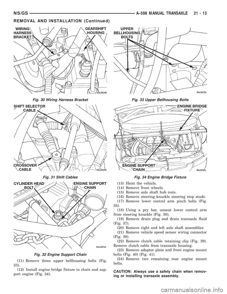
(11) Remove three upper bellhousing bolts (Fig.
33).
(12) Install engine bridge fixture to chain and sup-
port engine (Fig. 34).(13) Hoist the vehicle.
(14) Remove front wheels.
(15) Remove axle shaft hub nuts.
(16) Remove steering knuckle steering stop studs.
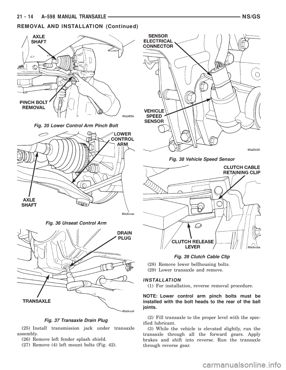
(17) Remove lower control arm pinch bolts (Fig.
35).
(18) Using a pry bar, unseat lower control arm
from steering knuckle (Fig. 36).
(19) Remove drain plug and drain transaxle fluid
(Fig. 37).
(20) Remove right and left axle shaft assemblies
(21) Remove vehicle speed sensor wiring connector
(Fig. 38).
(22) Remove clutch cable retaining clip (Fig. 39).
Remove clutch cable from transaxle housing.
(23) Remove adapter plate and front engine mount
bolts (Fig. 40) (Fig. 41).
(24) Remove two remaining rear engine mount
bolts.
CAUTION: Always use a safety chain when remov-
ing or installing transaxle assembly.
Fig. 30 Wiring Harness Bracket
Fig. 31 Shift Cables
Fig. 32 Engine Support Chain
Fig. 33 Upper Bellhousing Bolts
Fig. 34 Engine Bridge Fixture
NS/GSA±598 MANUAL TRANSAXLE 21 - 13
REMOVAL AND INSTALLATION (Continued)
Page 1670 of 1938
(25) Install transmission jack under transaxle
assembly.
(26) Remove left fender splash shield.
(27) Remove (4) left mount bolts (Fig. 42).(28) Remove lower bellhousing bolts.
(29) Lower transaxle and remove.
INSTALLATION
(1) For installation, reverse removal procedure.
NOTE: Lower control arm pinch bolts must be
installed with the bolt heads to the rear of the ball
joints.
(2) Fill transaxle to the proper level with the spec-
ified lubricant.
(3) While the vehicle is elevated slightly, run the
transaxle through all the forward gears. Apply
brakes and shift into reverse. Run the transaxle
through reverse gear.
Fig. 35 Lower Control Arm Pinch Bolt
Fig. 36 Unseat Control Arm
Fig. 37 Transaxle Drain Plug
Fig. 38 Vehicle Speed Sensor
Fig. 39 Clutch Cable Clip
21 - 14 A±598 MANUAL TRANSAXLENS/GS
REMOVAL AND INSTALLATION (Continued)
Page 1671 of 1938
(4) Check the transaxle for leaks and recheck the
level of the transaxle lubricant.
INPUT SHAFT FRONT BEARING RETAINER
REMOVAL
(1) Remove the transaxle assembly from the vehi-
cle. For removal procedure, refer to Transaxle,
Removal and Installation.
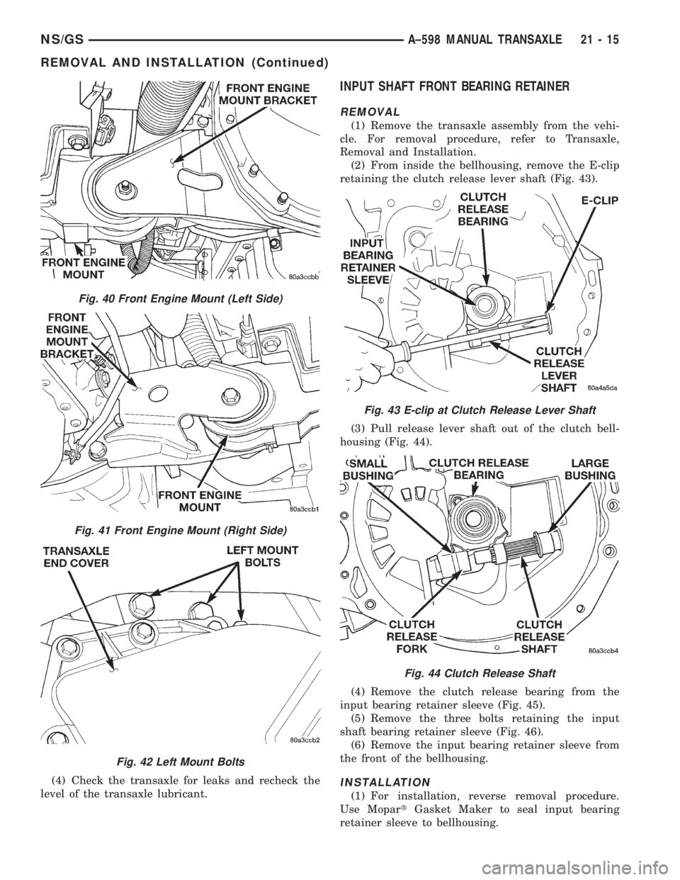
(2) From inside the bellhousing, remove the E-clip
retaining the clutch release lever shaft (Fig. 43).
(3) Pull release lever shaft out of the clutch bell-
housing (Fig. 44).
(4) Remove the clutch release bearing from the
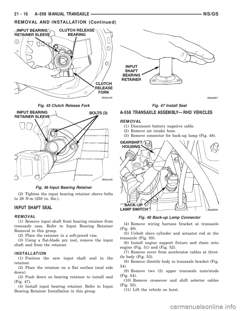
input bearing retainer sleeve (Fig. 45).
(5) Remove the three bolts retaining the input
shaft bearing retainer sleeve (Fig. 46).
(6) Remove the input bearing retainer sleeve from
the front of the bellhousing.
INSTALLATION
(1) For installation, reverse removal procedure.
Use MopartGasket Maker to seal input bearing
retainer sleeve to bellhousing.
Fig. 40 Front Engine Mount (Left Side)
Fig. 41 Front Engine Mount (Right Side)
Fig. 42 Left Mount Bolts
Fig. 43 E-clip at Clutch Release Lever Shaft
Fig. 44 Clutch Release Shaft
NS/GSA±598 MANUAL TRANSAXLE 21 - 15
REMOVAL AND INSTALLATION (Continued)
Page 1672 of 1938
(2) Tighten the input bearing retainer sleeve bolts
to 28 N´m (250 in. lbs.).
INPUT SHAFT SEAL
REMOVAL
(1) Remove input shaft front bearing retainer from
transaxle case. Refer to Input Bearing Retainer
Removal in this group.
(2) Place the retainer in a soft-jawed vise.
(3) Using a flat-blade pry tool, remove the input
shaft seal from the retainer.
INSTALLATION
(1) Position the new input shaft seal in the
retainer.
(2) Place the retainer on a flat surface (seal side
down).
(3) Push down on bearing retainer to install seal
(Fig. 47).
(4) Install input bearing retainer. Refer to Input
Bearing Retainer Installation in this group.
A-558 TRANSAXLE ASSEMBLYÐRHD VEHICLES
REMOVAL
(1) Disconnect battery negative cable.
(2) Remove air intake hose.
(3) Remove connector for back-up lamp (Fig. 48).
(4) Remove wiring harness bracket at transaxle
(Fig. 49).
(5) Unbolt slave cylinder and actuator rod at the
transaxle (Fig. 50).
(6) Install engine support fixture and chain onto
engine (Fig. 51) and (Fig. 52).
(7) Remove cover from accelerator cables at throt-
tle body (Fig. 53).
(8) Remove throttle body to transaxle bracket (Fig.
54).
(9) Remove two (2) upper transaxle nuts/studs
(Fig. 54).
(10) Remove crossover and shift selector cables
(Fig. 55).
(11) Lift the vehicle on hoist.
Fig. 45 Clutch Release Fork
Fig. 46 Input Bearing Retainer
Fig. 47 Install Seal
Fig. 48 Back-up Lamp Connector
21 - 16 A±598 MANUAL TRANSAXLENS/GS
REMOVAL AND INSTALLATION (Continued)
Page 1673 of 1938
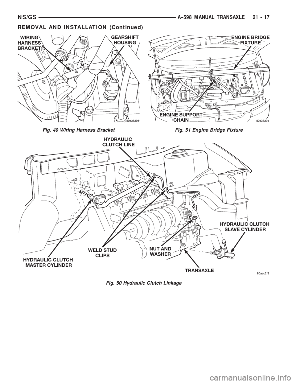
Fig. 49 Wiring Harness Bracket
Fig. 50 Hydraulic Clutch Linkage
Fig. 51 Engine Bridge Fixture
NS/GSA±598 MANUAL TRANSAXLE 21 - 17
REMOVAL AND INSTALLATION (Continued)
Page 1675 of 1938
(22) Remove lower starter bolt.
(23) Remove engine wiring harness clip.
CAUTION: Always use a safety chain when remov-
ing or installing transaxle assembly.
(24) Place a transmission jack under the transmis-
sion
(25) Remove the transaxle lower dust cover.
(26) Remove the access cover in right splash shield
to access torsional damper bolt.
(27) Remove drive plate to modular clutch bolts
while holding torsional damper bolt with socket and
ratchet. To avoid distortion of the drive plate, remove
the modular clutch bolts a few turns at a time. Use a
crisscross pattern until all bolts are loosened.
(28) Unbolt rear engine mount through bolt and
two (2) mount bolts.
(29) Remove the left front fender splash shield.
(30) Unbolt left engine mount through bolt and
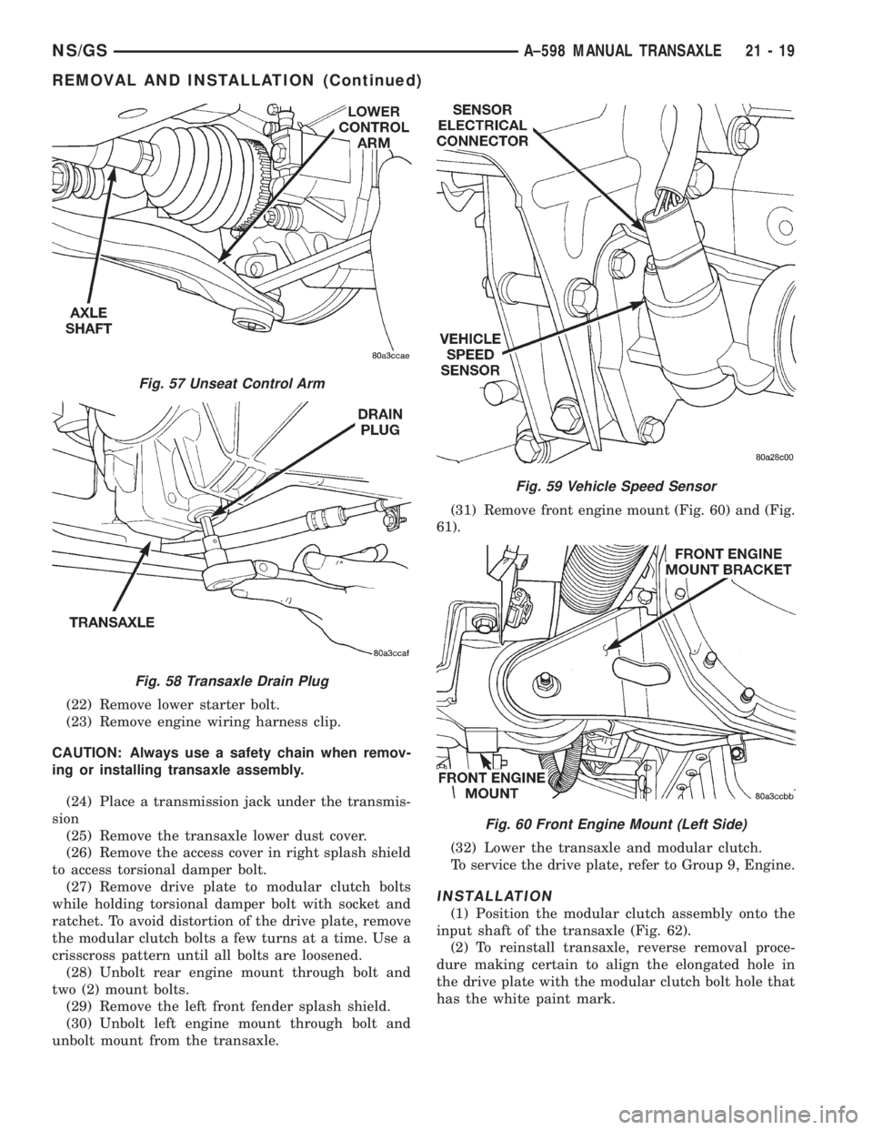
unbolt mount from the transaxle.(31) Remove front engine mount (Fig. 60) and (Fig.
61).
(32) Lower the transaxle and modular clutch.
To service the drive plate, refer to Group 9, Engine.
INSTALLATION
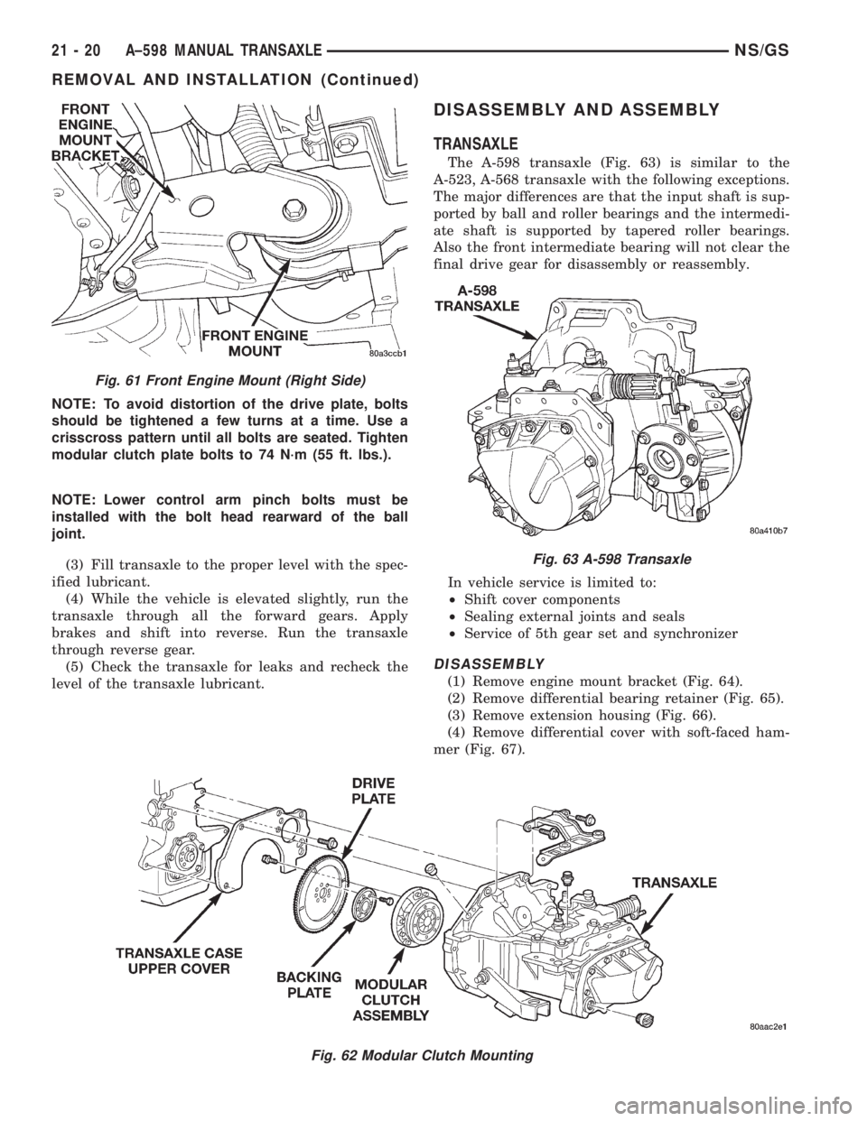
(1) Position the modular clutch assembly onto the
input shaft of the transaxle (Fig. 62).
(2) To reinstall transaxle, reverse removal proce-
dure making certain to align the elongated hole in
the drive plate with the modular clutch bolt hole that
has the white paint mark.
Fig. 57 Unseat Control Arm
Fig. 58 Transaxle Drain Plug
Fig. 59 Vehicle Speed Sensor
Fig. 60 Front Engine Mount (Left Side)
NS/GSA±598 MANUAL TRANSAXLE 21 - 19
REMOVAL AND INSTALLATION (Continued)
Page 1676 of 1938
NOTE: To avoid distortion of the drive plate, bolts
should be tightened a few turns at a time. Use a
crisscross pattern until all bolts are seated. Tighten
modular clutch plate bolts to 74 N´m (55 ft. lbs.).
NOTE: Lower control arm pinch bolts must be
installed with the bolt head rearward of the ball
joint.
(3) Fill transaxle to the proper level with the spec-
ified lubricant.
(4) While the vehicle is elevated slightly, run the
transaxle through all the forward gears. Apply
brakes and shift into reverse. Run the transaxle
through reverse gear.
(5) Check the transaxle for leaks and recheck the
level of the transaxle lubricant.
DISASSEMBLY AND ASSEMBLY
TRANSAXLE
The A-598 transaxle (Fig. 63) is similar to the
A-523, A-568 transaxle with the following exceptions.
The major differences are that the input shaft is sup-
ported by ball and roller bearings and the intermedi-
ate shaft is supported by tapered roller bearings.
Also the front intermediate bearing will not clear the
final drive gear for disassembly or reassembly.
In vehicle service is limited to:
²Shift cover components
²Sealing external joints and seals
²Service of 5th gear set and synchronizer
DISASSEMBLY
(1) Remove engine mount bracket (Fig. 64).
(2) Remove differential bearing retainer (Fig. 65).
(3) Remove extension housing (Fig. 66).
(4) Remove differential cover with soft-faced ham-
mer (Fig. 67).
Fig. 62 Modular Clutch Mounting
Fig. 61 Front Engine Mount (Right Side)
Fig. 63 A-598 Transaxle
21 - 20 A±598 MANUAL TRANSAXLENS/GS
REMOVAL AND INSTALLATION (Continued)