1996 CHRYSLER VOYAGER clutch
[x] Cancel search: clutchPage 1549 of 1938
DIAGNOSIS AND TESTING
41TE TRANSAXLE GENERAL DIAGNOSIS
CAUTION: Before attempting any repair on a 41TE
four speed automatic transaxle, check for Diagnos-
tic Trouble Codes with the DRBIII scan tool. Always
use the Powertrain Diagnostic Test Procedure Man-
ual.
Transaxle malfunctions may be caused by these
general conditions:
²Poor engine performance
²Improper adjustments
²Hydraulic malfunctions
²Mechanical malfunctions
²Electronic malfunctions
Diagnosis of these problems should always begin
by checking the easily accessible variables: fluid level
and condition, gearshift cable adjustment. Then per-
form a road test to determine if the problem has been
corrected or that more diagnosis is necessary. If the
problem persists after the preliminary tests and cor-
rections are completed, hydraulic pressure checks
should be performed.
ROAD TEST
Prior to performing a road test, check the fluid
level.
During the road test, the transaxle should be oper-
ated in each position to check for slipping and any
variation in shifting.If vehicle operates properly at high speeds, but has
poor acceleration, the converter's overrunning clutch
may be slipping. If acceleration is normal, but high
throttle opening is needed for high speeds, the clutch
may have seized. Both of these stator defects require
replacement of the torque converter.
The clutch that is slipping can be determined by
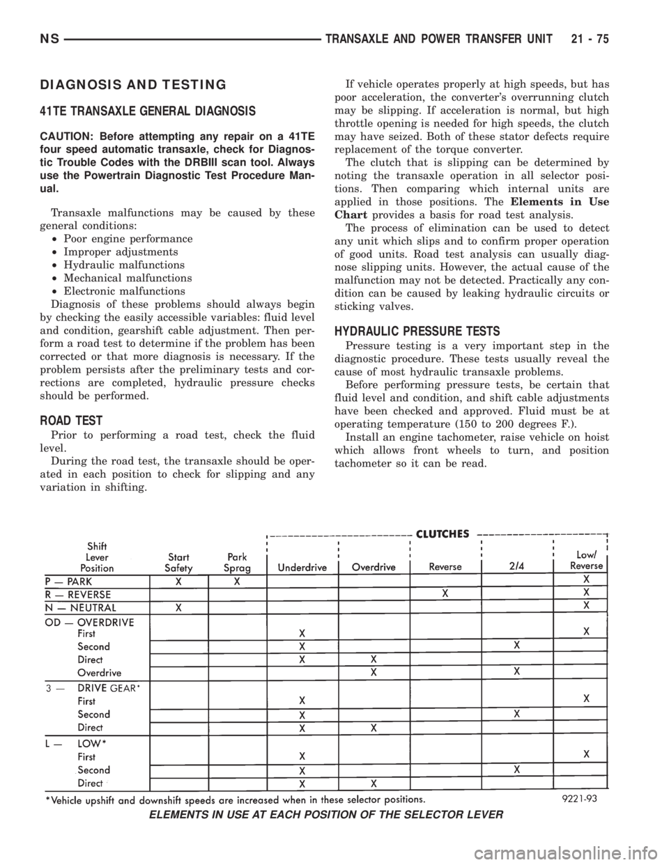
noting the transaxle operation in all selector posi-
tions. Then comparing which internal units are
applied in those positions. TheElements in Use
Chartprovides a basis for road test analysis.
The process of elimination can be used to detect
any unit which slips and to confirm proper operation
of good units. Road test analysis can usually diag-
nose slipping units. However, the actual cause of the
malfunction may not be detected. Practically any con-
dition can be caused by leaking hydraulic circuits or
sticking valves.
HYDRAULIC PRESSURE TESTS
Pressure testing is a very important step in the
diagnostic procedure. These tests usually reveal the
cause of most hydraulic transaxle problems.
Before performing pressure tests, be certain that
fluid level and condition, and shift cable adjustments
have been checked and approved. Fluid must be at
operating temperature (150 to 200 degrees F.).
Install an engine tachometer, raise vehicle on hoist
which allows front wheels to turn, and position
tachometer so it can be read.
ELEMENTS IN USE AT EACH POSITION OF THE SELECTOR LEVER
NSTRANSAXLE AND POWER TRANSFER UNIT 21 - 75
Page 1550 of 1938
Attach 150 psi gauges to ports required for test
being conducted. A 300 psi gauge (C-3293) is required
for reverse pressure test.
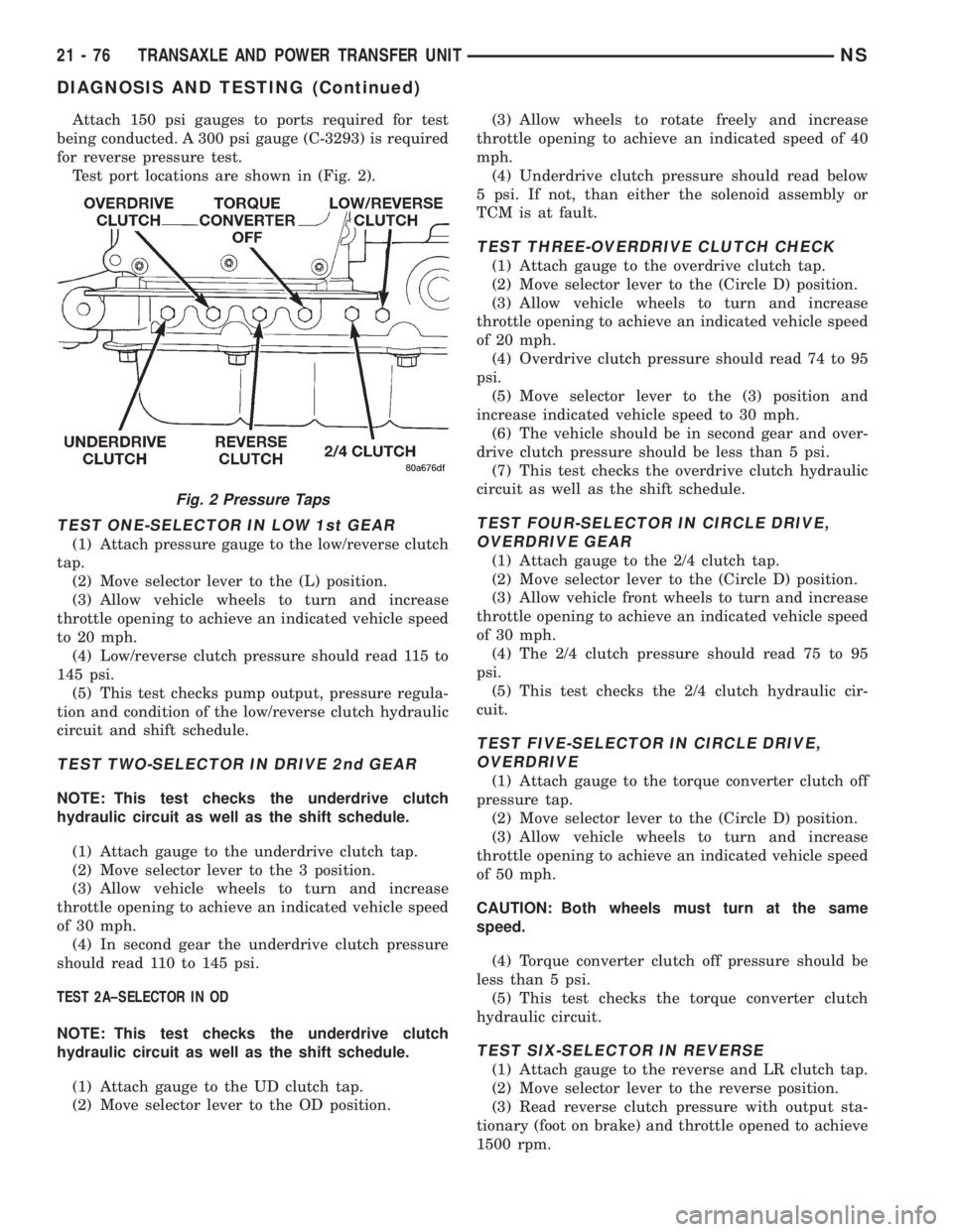
Test port locations are shown in (Fig. 2).
TEST ONE-SELECTOR IN LOW 1st GEAR
(1) Attach pressure gauge to the low/reverse clutch
tap.
(2) Move selector lever to the (L) position.
(3) Allow vehicle wheels to turn and increase
throttle opening to achieve an indicated vehicle speed
to 20 mph.
(4) Low/reverse clutch pressure should read 115 to
145 psi.
(5) This test checks pump output, pressure regula-
tion and condition of the low/reverse clutch hydraulic
circuit and shift schedule.
TEST TWO-SELECTOR IN DRIVE 2nd GEAR
NOTE: This test checks the underdrive clutch
hydraulic circuit as well as the shift schedule.
(1) Attach gauge to the underdrive clutch tap.
(2) Move selector lever to the 3 position.
(3) Allow vehicle wheels to turn and increase
throttle opening to achieve an indicated vehicle speed
of 30 mph.
(4) In second gear the underdrive clutch pressure
should read 110 to 145 psi.
TEST 2A±SELECTOR IN OD
NOTE: This test checks the underdrive clutch
hydraulic circuit as well as the shift schedule.
(1) Attach gauge to the UD clutch tap.
(2) Move selector lever to the OD position.(3) Allow wheels to rotate freely and increase
throttle opening to achieve an indicated speed of 40
mph.
(4) Underdrive clutch pressure should read below
5 psi. If not, than either the solenoid assembly or
TCM is at fault.
TEST THREE-OVERDRIVE CLUTCH CHECK
(1) Attach gauge to the overdrive clutch tap.
(2) Move selector lever to the (Circle D) position.
(3) Allow vehicle wheels to turn and increase
throttle opening to achieve an indicated vehicle speed
of 20 mph.
(4) Overdrive clutch pressure should read 74 to 95
psi.
(5) Move selector lever to the (3) position and
increase indicated vehicle speed to 30 mph.
(6) The vehicle should be in second gear and over-
drive clutch pressure should be less than 5 psi.
(7) This test checks the overdrive clutch hydraulic
circuit as well as the shift schedule.
TEST FOUR-SELECTOR IN CIRCLE DRIVE,
OVERDRIVE GEAR
(1) Attach gauge to the 2/4 clutch tap.
(2) Move selector lever to the (Circle D) position.
(3) Allow vehicle front wheels to turn and increase
throttle opening to achieve an indicated vehicle speed
of 30 mph.
(4) The 2/4 clutch pressure should read 75 to 95
psi.
(5) This test checks the 2/4 clutch hydraulic cir-
cuit.
TEST FIVE-SELECTOR IN CIRCLE DRIVE,
OVERDRIVE
(1) Attach gauge to the torque converter clutch off
pressure tap.
(2) Move selector lever to the (Circle D) position.
(3) Allow vehicle wheels to turn and increase
throttle opening to achieve an indicated vehicle speed
of 50 mph.
CAUTION: Both wheels must turn at the same
speed.
(4) Torque converter clutch off pressure should be
less than 5 psi.
(5) This test checks the torque converter clutch
hydraulic circuit.
TEST SIX-SELECTOR IN REVERSE
(1) Attach gauge to the reverse and LR clutch tap.
(2) Move selector lever to the reverse position.
(3) Read reverse clutch pressure with output sta-
tionary (foot on brake) and throttle opened to achieve
1500 rpm.
Fig. 2 Pressure Taps
21 - 76 TRANSAXLE AND POWER TRANSFER UNITNS
DIAGNOSIS AND TESTING (Continued)
Page 1551 of 1938

(4) Reverse and LR clutch pressure should read
165 to 235 psi.
(5) This test checks the reverse clutch hydraulic
circuit.
TEST RESULT INDICATIONS
(1) If proper line pressure is found in any one test,
the pump and pressure regulator are working prop-
erly.
(2) Low pressure in all positions indicates a defec-
tive pump, a clogged filter, or a stuck pressure regu-
lator valve.
(3) Clutch circuit leaks are indicated if pressures
do not fall within the specified pressure range.
(4) If the overdrive clutch pressure is greater than
5 psi in Step 4 of Test Three, a worn reaction shaft
seal ring or a defective solenoid assembly is indi-
cated.
(5) If the underdrive clutch pressure is greater
than 5 psi in Step 4 of Test 2A, a defective solenoid
assembly or TCM is the cause.
CLUTCH AIR PRESSURE TESTS
Inoperative clutches can be located using a series
of tests by substituting air pressure for fluid pressure
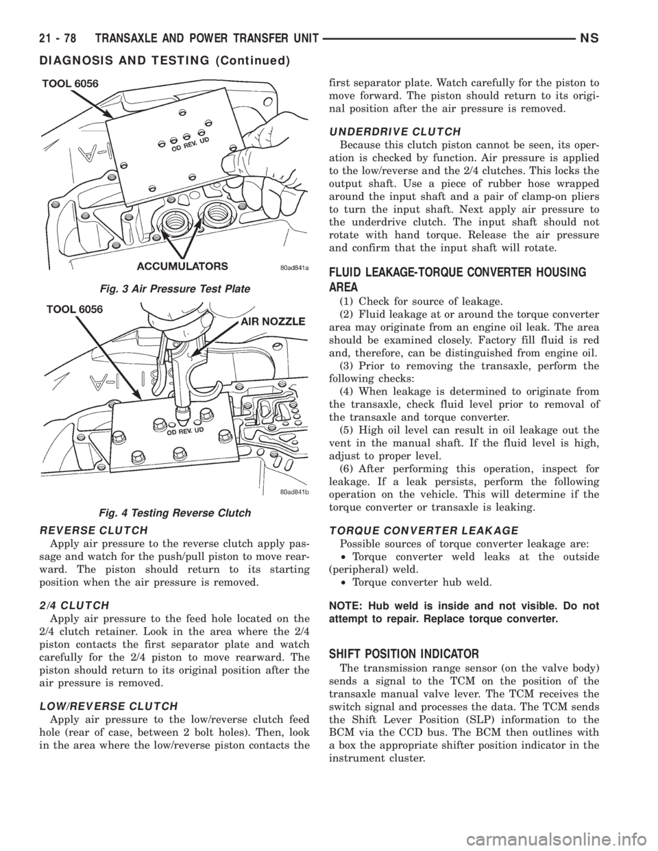
(Fig. 3) (Fig. 4). The clutches may be tested by apply-
ing air pressure to their respective passages. The
valve body must be removed and Tool 6056 installed.
To make air pressure tests, proceed as follows:
NOTE: The compressed air supply must be free of
all dirt and moisture. Use a pressure of 30 psi.
Remove oil pan and valve body. See Valve body
removal.
OVERDRIVE CLUTCH
Apply air pressure to the overdrive clutch apply
passage and watch for the push/pull piston to move
forward. The piston should return to its starting
position when the air pressure is removed.
PRESSURE CHECK SPECIFICATIONS
NSTRANSAXLE AND POWER TRANSFER UNIT 21 - 77
DIAGNOSIS AND TESTING (Continued)
Page 1552 of 1938
REVERSE CLUTCH
Apply air pressure to the reverse clutch apply pas-
sage and watch for the push/pull piston to move rear-
ward. The piston should return to its starting
position when the air pressure is removed.
2/4 CLUTCH
Apply air pressure to the feed hole located on the
2/4 clutch retainer. Look in the area where the 2/4
piston contacts the first separator plate and watch
carefully for the 2/4 piston to move rearward. The
piston should return to its original position after the
air pressure is removed.
LOW/REVERSE CLUTCH
Apply air pressure to the low/reverse clutch feed
hole (rear of case, between 2 bolt holes). Then, look
in the area where the low/reverse piston contacts thefirst separator plate. Watch carefully for the piston to
move forward. The piston should return to its origi-
nal position after the air pressure is removed.
UNDERDRIVE CLUTCH
Because this clutch piston cannot be seen, its oper-
ation is checked by function. Air pressure is applied
to the low/reverse and the 2/4 clutches. This locks the
output shaft. Use a piece of rubber hose wrapped
around the input shaft and a pair of clamp-on pliers
to turn the input shaft. Next apply air pressure to
the underdrive clutch. The input shaft should not
rotate with hand torque. Release the air pressure
and confirm that the input shaft will rotate.
FLUID LEAKAGE-TORQUE CONVERTER HOUSING
AREA
(1) Check for source of leakage.
(2) Fluid leakage at or around the torque converter
area may originate from an engine oil leak. The area
should be examined closely. Factory fill fluid is red
and, therefore, can be distinguished from engine oil.
(3) Prior to removing the transaxle, perform the
following checks:
(4) When leakage is determined to originate from
the transaxle, check fluid level prior to removal of
the transaxle and torque converter.
(5) High oil level can result in oil leakage out the
vent in the manual shaft. If the fluid level is high,
adjust to proper level.
(6) After performing this operation, inspect for
leakage. If a leak persists, perform the following
operation on the vehicle. This will determine if the
torque converter or transaxle is leaking.
TORQUE CONVERTER LEAKAGE
Possible sources of torque converter leakage are:
²Torque converter weld leaks at the outside
(peripheral) weld.
²Torque converter hub weld.
NOTE: Hub weld is inside and not visible. Do not
attempt to repair. Replace torque converter.
SHIFT POSITION INDICATOR
The transmission range sensor (on the valve body)
sends a signal to the TCM on the position of the
transaxle manual valve lever. The TCM receives the
switch signal and processes the data. The TCM sends
the Shift Lever Position (SLP) information to the
BCM via the CCD bus. The BCM then outlines with
a box the appropriate shifter position indicator in the
instrument cluster.
Fig. 3 Air Pressure Test Plate
Fig. 4 Testing Reverse Clutch
21 - 78 TRANSAXLE AND POWER TRANSFER UNITNS
DIAGNOSIS AND TESTING (Continued)
Page 1556 of 1938
WARNING: WEAR PROTECTIVE EYEWEAR THAT
MEETS THE REQUIREMENTS OF OSHA AND ANSI
Z87.1±1968. WEAR STANDARD INDUSTRIAL RUB-
BER GLOVES.
KEEP LIGHTED CIGARETTES, SPARKS, FLAMES,
AND OTHER IGNITION SOURCES AWAY FROM THE
AREA TO PREVENT THE IGNITION OF COMBUSTI-
BLE LIQUIDS AND GASES. KEEP A CLASS (B) FIRE
EXTINGUISHER IN THE AREA WHERE THE
FLUSHER WILL BE USED.
KEEP THE AREA WELL VENTILATED.
DO NOT LET FLUSHING SOLVENT COME IN CON-
TACT WITH YOUR EYES OR SKIN: IF EYE CONTAM-
INATION OCCURS, FLUSH EYES WITH WATER FOR
15 TO 20 SECONDS. REMOVE CONTAMINATED
CLOTHING AND WASH AFFECTED SKIN WITH
SOAP AND WATER. SEEK MEDICAL ATTENTION.
COOLER FLUSH USING TOOL 6906A
(1) Remove cover plate filler plug on Tool 6906A.
Fill reservoir 1/2 to 3/4 full of fresh flushing solution.
Flushing solvents are petroleum based solutions gen-
erally used to clean automatic transmission compo-
nents.DO NOTuse solvents containing acids, water,
gasoline, or any other corrosive liquids.
(2) Reinstall filler plug on Tool 6906A.
(3) Verify pump power switch is turned OFF. Con-
nect red alligator clip to positive (+) battery post.
Connect black (-) alligator clip to a good ground.
(4) Disconnect the cooler lines at the transmission.
NOTE: When flushing transmission cooler and
lines, ALWAYS reverse flush.
(5) Connect the BLUE pressure line to the OUT-
LET (From) cooler line.
(6) Connect the CLEAR return line to the INLET
(To) cooler line
(7) Turn pump ON for two to three minutes to
flush cooler(s) and lines. Monitor pressure readings
and clear return lines. Pressure readings should sta-
bilize below 20 psi. for vehicles equipped with a sin-
gle cooler and 30 psi. for vehicles equipped with dual
coolers. If flow is intermittent or exceeds these pres-
sures, replace cooler.
(8) Turn pump OFF.
(9) Disconnect CLEAR suction line from reservoir
at cover plate. Disconnect CLEAR return line at
cover plate, and place it in a drain pan.
(10) Turn pump ON for 30 seconds to purge flush-
ing solution from cooler and lines. Turn pump OFF.
(11) Place CLEAR suction line into a one quart
container of MopartATF PLUS 3 Type 7176 auto-
matic transmission fluid.
(12) Turn pump ON until all transmission fluid is
removed from the one quart container and lines. Thispurges any residual cleaning solvent from the trans-
mission cooler and lines. Turn pump OFF.
(13) Disconnect alligator clips from battery. Recon-
nect flusher lines to cover plate, and remove flushing
adapters from cooler lines.
OIL PUMP VOLUME CHECK
After the new or repaired transmission has been
installed, fill to the proper level with Mopar ATF
PLUS 3 (Type 7176) automatic transmission fluid.
The volume should be checked using the following
procedure:
(1) Disconnect theFrom coolerline at the trans-
mission and place a collecting container under the
disconnected line.
CAUTION: With the fluid set at the proper level,
fluid collection should not exceed (1) quart or inter-
nal damage to the transmission may occur.
(2) Run the engineat curb idle speed, with the
shift selector in neutral.
(3) If fluid flow is intermittent or it takes more
than 20 seconds to collect one quart of ATF, discon-
nect theTo Coolerline at the transaxle.
(4) Refill the transaxle to proper level and recheck
pump volume.
(5) If flow is found to be within acceptable limits,
replace the cooler. Then fill transmission to the
proper level, using Mopar ATF PLUS 3 (Type 7176)
automatic transmission fluid.
(6) If fluid flow is still found to be inadequate,
check the line pressure using the Transaxle Hydrau-
lic Pressure Test procedure.
(7) Check the cooler for debris on the external sur-
faces. Clean as necessary.
TRANSAXLE QUICK LEARN PROCEDURE
The quick learn procedure requires the use of the
DRBIII scan tool.
This program allows the electronic transaxle sys-
tem to recalibrate itself. This will provide the best
possible transaxle operation. The quick learn proce-
dure should be performed if any of the following pro-
cedures are performed:
²Transaxle Assembly Replacement
²Transmission Control Module Replacement
²Solenoid Pack Replacement
²Clutch Plate and/or Seal Replacement
²Valve Body Replacement or Recondition
To perform the Quick Learn Procedure, the follow-
ing conditions must be met:
²The brakes must be applied
²The engine speed must be above 500 rpm
²The throttle angle (TPS) must be less than 3
degrees
21 - 82 TRANSAXLE AND POWER TRANSFER UNITNS
SERVICE PROCEDURES (Continued)
Page 1569 of 1938
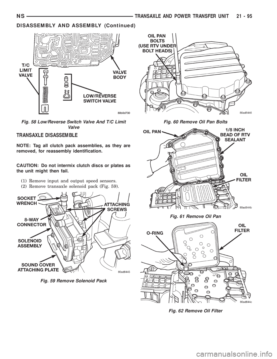
TRANSAXLE DISASSEMBLE
NOTE: Tag all clutch pack assemblies, as they are
removed, for reassembly identification.
CAUTION: Do not intermix clutch discs or plates as
the unit might then fail.
(1) Remove input and output speed sensors.
(2) Remove transaxle solenoid pack (Fig. 59).
Fig. 58 Low/Reverse Switch Valve And T/C Limit
Valve
Fig. 59 Remove Solenoid Pack
Fig. 60 Remove Oil Pan Bolts
Fig. 61 Remove Oil Pan
Fig. 62 Remove Oil Filter
NSTRANSAXLE AND POWER TRANSFER UNIT 21 - 95
DISASSEMBLY AND ASSEMBLY (Continued)
Page 1572 of 1938
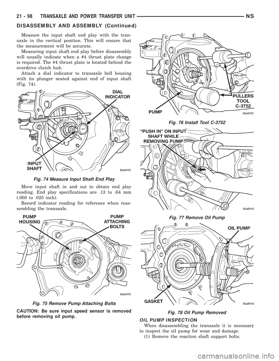
Measure the input shaft end play with the tran-
saxle in the vertical position. This will ensure that
the measurement will be accurate.
Measuring input shaft end play before disassembly
will usually indicate when a #4 thrust plate change
is required. The #4 thrust plate is located behind the
overdrive clutch hub.
Attach a dial indicator to transaxle bell housing
with its plunger seated against end of input shaft
(Fig. 74).
Move input shaft in and out to obtain end play
reading. End play specifications are .13 to .64 mm
(.005 to .025 inch).
Record indicator reading for reference when reas-
sembling the transaxle.
CAUTION: Be sure input speed sensor is removed
before removing oil pump.
OIL PUMP INSPECTION
When disassembling the transaxle it is necessary
to inspect the oil pump for wear and damage.
(1) Remove the reaction shaft support bolts.
Fig. 74 Measure Input Shaft End Play
Fig. 75 Remove Pump Attaching Bolts
Fig. 76 Install Tool C-3752
Fig. 77 Remove Oil Pump
Fig. 78 Oil Pump Removed
21 - 98 TRANSAXLE AND POWER TRANSFER UNITNS
DISASSEMBLY AND ASSEMBLY (Continued)
Page 1574 of 1938
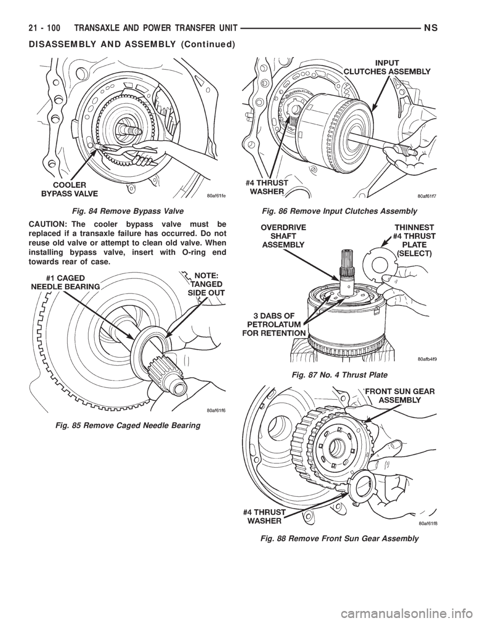
CAUTION: The cooler bypass valve must be
replaced if a transaxle failure has occurred. Do not
reuse old valve or attempt to clean old valve. When
installing bypass valve, insert with O-ring end
towards rear of case.
Fig. 84 Remove Bypass Valve
Fig. 85 Remove Caged Needle Bearing
Fig. 86 Remove Input Clutches Assembly
Fig. 87 No. 4 Thrust Plate
Fig. 88 Remove Front Sun Gear Assembly
21 - 100 TRANSAXLE AND POWER TRANSFER UNITNS
DISASSEMBLY AND ASSEMBLY (Continued)