1996 CHRYSLER VOYAGER clutch
[x] Cancel search: clutchPage 1507 of 1938
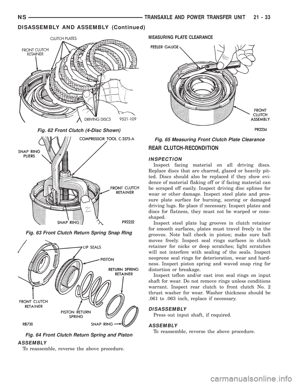
ASSEMBLY
To reassemble, reverse the above procedure.MEASURING PLATE CLEARANCE
REAR CLUTCH-RECONDITION
INSPECTION
Inspect facing material on all driving discs.
Replace discs that are charred, glazed or heavily pit-
ted. Discs should also be replaced if they show evi-
dence of material flaking off or if facing material can
be scraped off easily. Inspect driving disc splines for
wear or other damage. Inspect steel plate and pres-
sure plate surface for burning, scoring or damaged
driving lugs. Re place if necessary. Inspect plates and
discs for flatness, they must not be warped or cone-
shaped.
Inspect steel plate lug grooves in clutch retainer
for smooth surfaces, plates must travel freely in the
grooves. Note ball check in piston; make sure ball
moves freely. Inspect seal rings surfaces in clutch
retainer for nicks or deep scratches; light scratches
will not interfere with sealing of the seals. Inspect
neoprene seal rings for deterioration, wear and hard-
ness. Inspect piston spring and waved snap ring for
distortion or breakage.
Inspect teflon and/or cast iron seal rings on input
shaft for wear. Do not remove rings unless conditions
warrant. Inspect rear clutch to front clutch No. 2
thrust washer for wear. Washer thickness should be
.061 to .063 inch, replace if necessary.
DISASSEMBLY
Press out input shaft, if required.
ASSEMBLY
To reassemble, reverse the above procedure.
Fig. 62 Front Clutch (4-Disc Shown)
Fig. 63 Front Clutch Return Spring Snap Ring
Fig. 64 Front Clutch Return Spring and Piston
Fig. 65 Measuring Front Clutch Plate Clearance
NSTRANSAXLE AND POWER TRANSFER UNIT 21 - 33
DISASSEMBLY AND ASSEMBLY (Continued)
Page 1508 of 1938
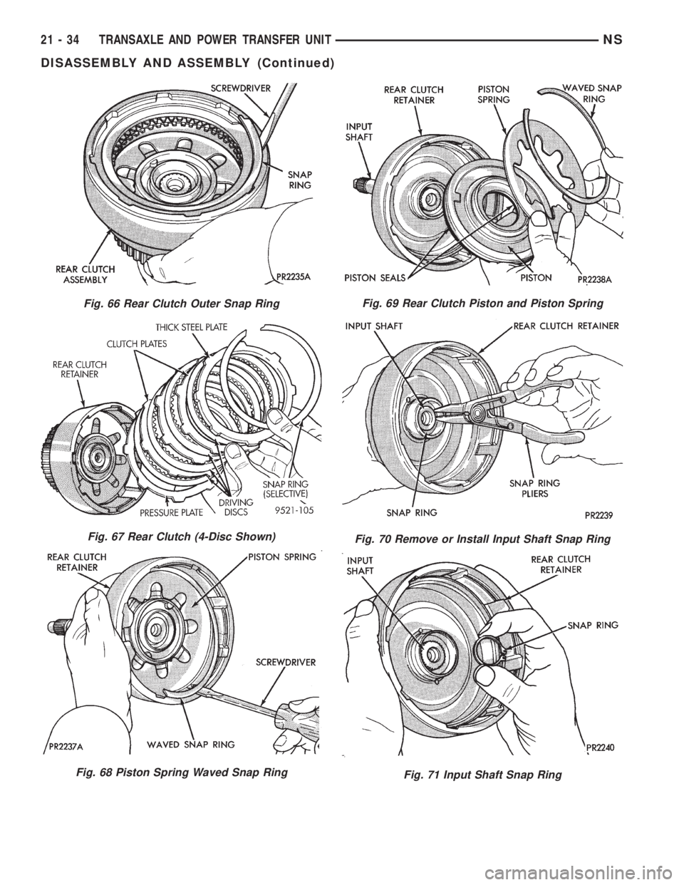
Fig. 66 Rear Clutch Outer Snap Ring
Fig. 67 Rear Clutch (4-Disc Shown)
Fig. 68 Piston Spring Waved Snap Ring
Fig. 69 Rear Clutch Piston and Piston Spring
Fig. 70 Remove or Install Input Shaft Snap Ring
Fig. 71 Input Shaft Snap Ring
21 - 34 TRANSAXLE AND POWER TRANSFER UNITNS
DISASSEMBLY AND ASSEMBLY (Continued)
Page 1509 of 1938
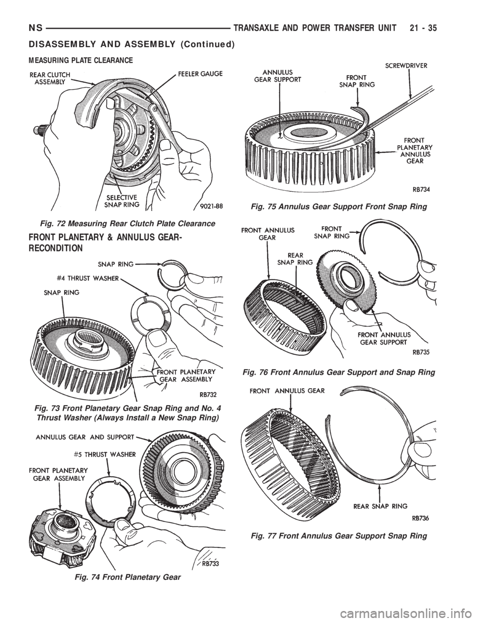
MEASURING PLATE CLEARANCE
FRONT PLANETARY & ANNULUS GEAR-
RECONDITION
Fig. 72 Measuring Rear Clutch Plate Clearance
Fig. 73 Front Planetary Gear Snap Ring and No. 4
Thrust Washer (Always Install a New Snap Ring)
Fig. 74 Front Planetary Gear
Fig. 75 Annulus Gear Support Front Snap Ring
Fig. 76 Front Annulus Gear Support and Snap Ring
Fig. 77 Front Annulus Gear Support Snap Ring
NSTRANSAXLE AND POWER TRANSFER UNIT 21 - 35
DISASSEMBLY AND ASSEMBLY (Continued)
Page 1519 of 1938
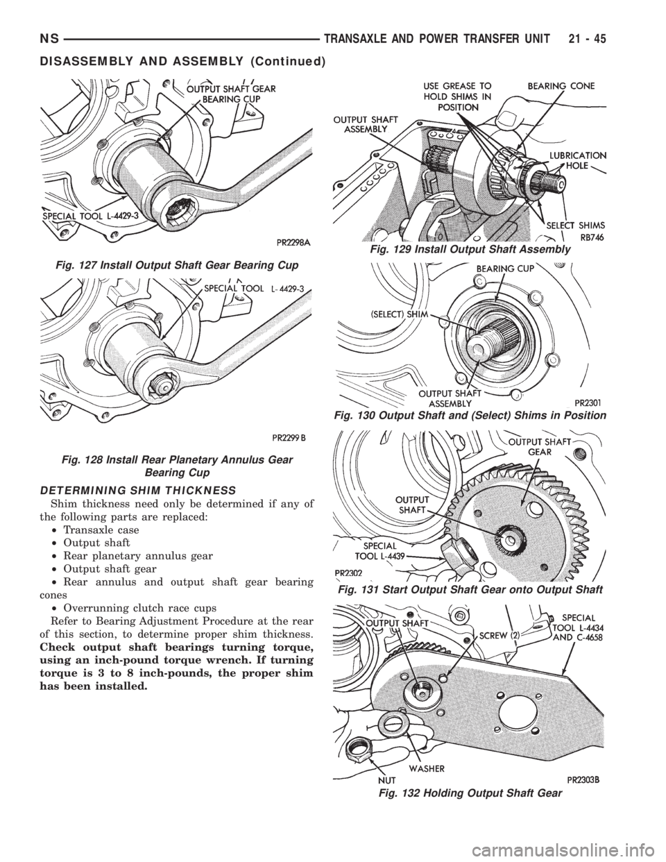
DETERMINING SHIM THICKNESS
Shim thickness need only be determined if any of
the following parts are replaced:
²Transaxle case
²Output shaft
²Rear planetary annulus gear
²Output shaft gear
²Rear annulus and output shaft gear bearing
cones
²Overrunning clutch race cups
Refer to Bearing Adjustment Procedure at the rear
of this section, to determine proper shim thickness.
Check output shaft bearings turning torque,
using an inch-pound torque wrench. If turning
torque is 3 to 8 inch-pounds, the proper shim
has been installed.
Fig. 127 Install Output Shaft Gear Bearing Cup
Fig. 128 Install Rear Planetary Annulus Gear
Bearing Cup
Fig. 129 Install Output Shaft Assembly
Fig. 130 Output Shaft and (Select) Shims in Position
Fig. 131 Start Output Shaft Gear onto Output Shaft
Fig. 132 Holding Output Shaft Gear
NSTRANSAXLE AND POWER TRANSFER UNIT 21 - 45
DISASSEMBLY AND ASSEMBLY (Continued)
Page 1538 of 1938
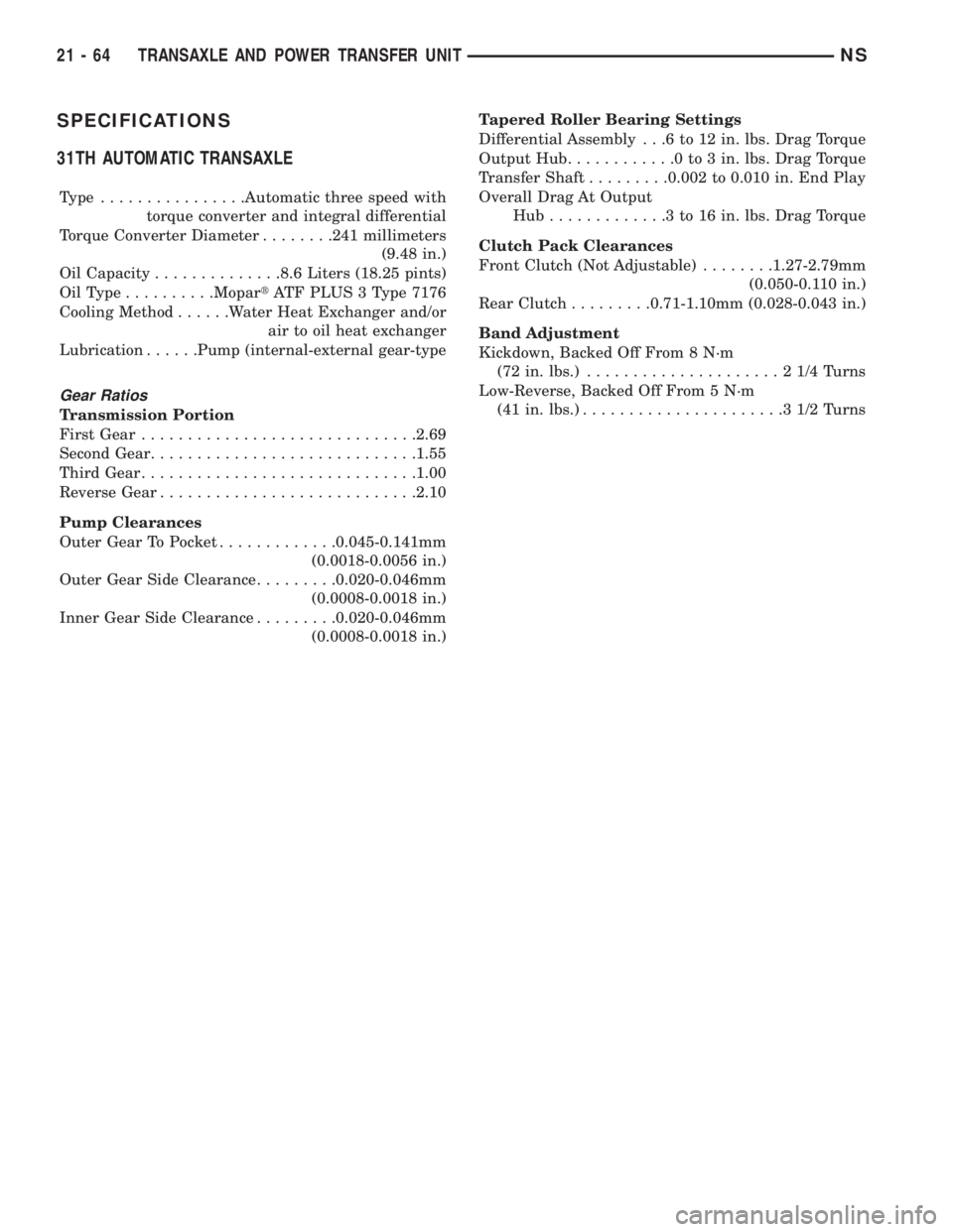
SPECIFICATIONS
31TH AUTOMATIC TRANSAXLE
Type ................Automatic three speed with
torque converter and integral differential
Torque Converter Diameter........241 millimeters
(9.48 in.)
Oil Capacity..............8.6 Liters (18.25 pints)
OilType..........MopartATF PLUS 3 Type 7176
Cooling Method......Water Heat Exchanger and/or
air to oil heat exchanger
Lubrication......Pump (internal-external gear-type
Gear Ratios
Transmission Portion
First Gear..............................2.69
Second Gear.............................1.55
Third Gear..............................1.00
Reverse Gear............................2.10
Pump Clearances
Outer Gear To Pocket.............0.045-0.141mm
(0.0018-0.0056 in.)
Outer Gear Side Clearance.........0.020-0.046mm
(0.0008-0.0018 in.)
Inner Gear Side Clearance.........0.020-0.046mm
(0.0008-0.0018 in.)Tapered Roller Bearing Settings
Differential Assembly . . .6 to 12 in. lbs. Drag Torque
Output Hub............0to3in.lbs. Drag Torque
Transfer Shaft.........0.002 to 0.010 in. End Play
Overall Drag At Output
Hub.............3to16in.lbs. Drag Torque
Clutch Pack Clearances
Front Clutch (Not Adjustable)........1.27-2.79mm
(0.050-0.110 in.)
Rear Clutch.........0.71-1.10mm (0.028-0.043 in.)
Band Adjustment
Kickdown, Backed Off From 8 N´m
(72 in. lbs.).....................21/4Turns
Low-Reverse, Backed Off From 5 N´m
(41 in. lbs.)......................31/2Turns
21 - 64 TRANSAXLE AND POWER TRANSFER UNITNS
Page 1545 of 1938

41TE AUTOMATIC TRANSAXLE
INDEX
page page
GENERAL INFORMATION
41TE FOUR SPEED AUTOMATIC TRANSAXLE . 71
FLUID LEVEL AND CONDITION............. 72
SELECTION OF LUBRICANT............... 72
SPECIAL ADDITIVES..................... 72
DESCRIPTION AND OPERATION
ADAPTIVE CONTROLS................... 73
CLUTCH AND GEAR..................... 72
ELECTRONICS......................... 73
GEARSHIFT AND PARKING LOCK CONTROLS . 74
HYDRAULICS........................... 73
ON-BOARD DIAGNOSTICS................ 74
SENSORS............................. 73
SHIFT POSITION INDICATOR.............. 74
SOLENOIDS............................ 73
TORQUE MANAGEMENT.................. 74
TRANSMISSION CONTROL MODULE........ 74
TRANSMISSION RANGE SENSOR........... 74
DIAGNOSIS AND TESTING
41TE TRANSAXLE GENERAL DIAGNOSIS..... 75
CLUTCH AIR PRESSURE TESTS............ 77
FLUID LEAKAGE-TORQUE CONVERTER
HOUSING AREA....................... 78
HYDRAULIC PRESSURE TESTS............ 75
ROAD TEST............................ 75
SHIFT POSITION INDICATOR.............. 78
SERVICE PROCEDURES
ALUMINUM THREAD REPAIR.............. 81
FLUID AND FILTER CHANGE............... 79
FLUID DRAIN AND REFILL................. 81
FLUSHING COOLERS AND TUBES.......... 81OIL PUMP VOLUME CHECK............... 82
PINION FACTOR PROCEDURE............. 83
TRANSAXLE QUICK LEARN PROCEDURE.... 82
REMOVAL AND INSTALLATION
GEARSHIFT CABLE...................... 83
MANUAL VALVE LEVER (SHIFT LEVER)...... 84
OIL PUMP SEAL......................... 92
SOLENOID ASSEMBLY-REPLACE........... 85
SPEED SENSOR-INPUT................... 86
SPEED SENSOR-OUTPUT................. 86
TRANSAXLE........................... 89
TRANSMISSION CONTROL MODULE........ 87
TRANSMISSION RANGE SENSOR........... 85
VALVE BODY........................... 88
DISASSEMBLY AND ASSEMBLY
DIFFERENTIAL REPAIR.................. 139
INPUT CLUTCHES-RECONDITION.......... 110
TRANSAXLE ASSEMBLE................. 122
TRANSAXLE DISASSEMBLE............... 95
VALVE BODY RECONDITION............... 92
CLEANING AND INSPECTION
CLEANING VALVE BODY................. 144
ADJUSTMENTS
GEARSHIFT CABLE ADJUSTMENT......... 144
SCHEMATICS AND DIAGRAMS
41TE TRANSAXLE HYDRAULIC SCHEMATICS . 145
SPECIFICATIONS
41TE AUTOMATIC TRANSAXLE............ 158
41TE TORQUE SPECIFICATIONS.......... 158
SPECIAL TOOLS
41TE AUTOMATIC TRANSAXLE............ 159
GENERAL INFORMATION
41TE FOUR SPEED AUTOMATIC TRANSAXLE
The 41TE four-speed FWD transaxle uses fully-
adaptive controls. Adaptive controls are those which
perform their functions based on real-time feedback
sensor information. The transaxle uses hydraulically
applied clutches to shift a planetary gear train.
TRANSAXLE IDENTIFICATION
The 41TE transaxle identification code is printed
on a label. The label is located on the transaxle case
next to the solenoid assembly (Fig. 1).
Fig. 1 Identification Tag Location
NSTRANSAXLE AND POWER TRANSFER UNIT 21 - 71
Page 1546 of 1938
OPERATION
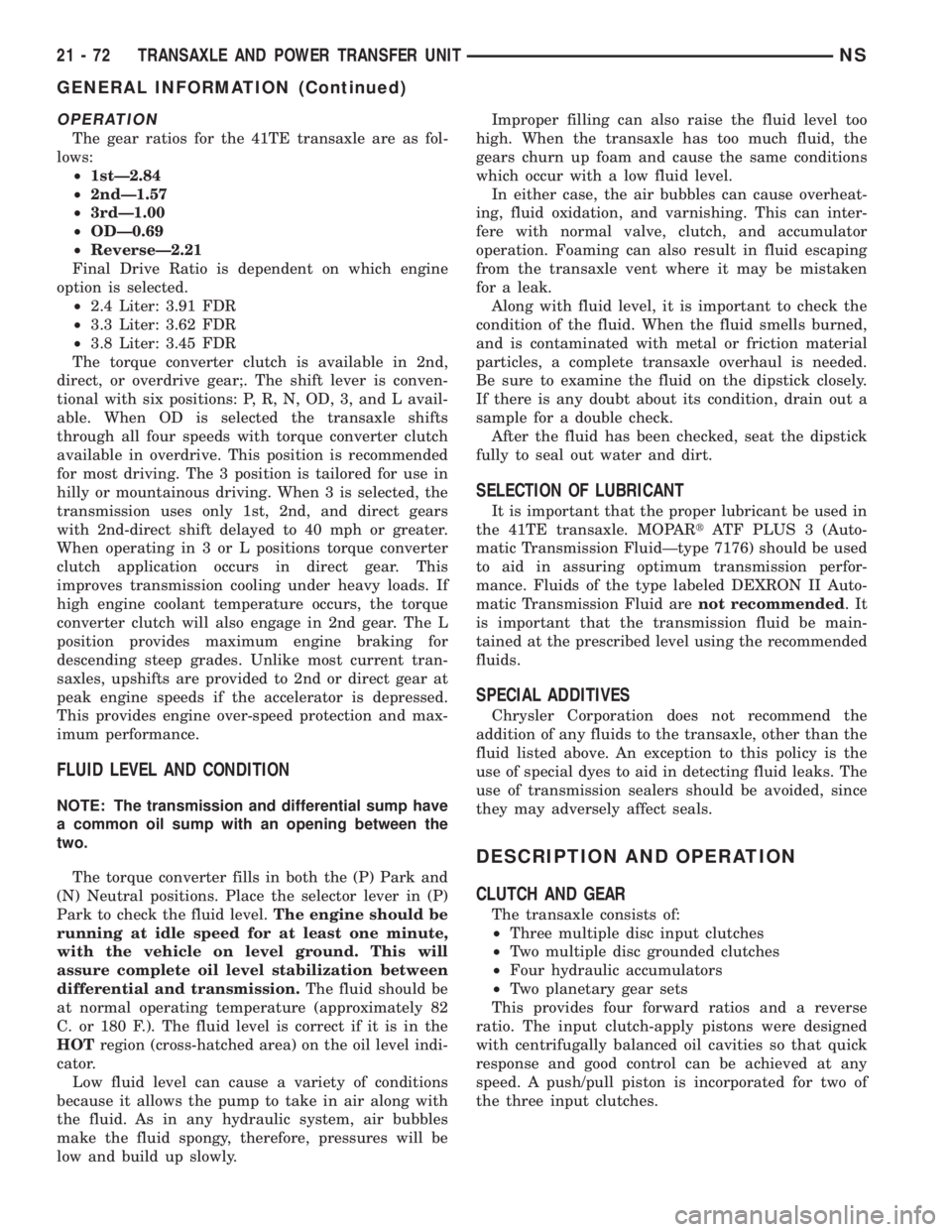
The gear ratios for the 41TE transaxle are as fol-
lows:
²1stÐ2.84
²2ndÐ1.57
²3rdÐ1.00
²ODÐ0.69
²ReverseÐ2.21
Final Drive Ratio is dependent on which engine
option is selected.
²2.4 Liter: 3.91 FDR
²3.3 Liter: 3.62 FDR
²3.8 Liter: 3.45 FDR
The torque converter clutch is available in 2nd,
direct, or overdrive gear;. The shift lever is conven-
tional with six positions: P, R, N, OD, 3, and L avail-
able. When OD is selected the transaxle shifts
through all four speeds with torque converter clutch
available in overdrive. This position is recommended
for most driving. The 3 position is tailored for use in
hilly or mountainous driving. When 3 is selected, the
transmission uses only 1st, 2nd, and direct gears
with 2nd-direct shift delayed to 40 mph or greater.
When operating in 3 or L positions torque converter
clutch application occurs in direct gear. This
improves transmission cooling under heavy loads. If
high engine coolant temperature occurs, the torque
converter clutch will also engage in 2nd gear. The L
position provides maximum engine braking for
descending steep grades. Unlike most current tran-
saxles, upshifts are provided to 2nd or direct gear at
peak engine speeds if the accelerator is depressed.
This provides engine over-speed protection and max-
imum performance.
FLUID LEVEL AND CONDITION
NOTE: The transmission and differential sump have
a common oil sump with an opening between the
two.
The torque converter fills in both the (P) Park and
(N) Neutral positions. Place the selector lever in (P)
Park to check the fluid level.The engine should be
running at idle speed for at least one minute,
with the vehicle on level ground. This will
assure complete oil level stabilization between
differential and transmission.The fluid should be
at normal operating temperature (approximately 82
C. or 180 F.). The fluid level is correct if it is in the
HOTregion (cross-hatched area) on the oil level indi-
cator.
Low fluid level can cause a variety of conditions
because it allows the pump to take in air along with
the fluid. As in any hydraulic system, air bubbles
make the fluid spongy, therefore, pressures will be
low and build up slowly.Improper filling can also raise the fluid level too
high. When the transaxle has too much fluid, the
gears churn up foam and cause the same conditions
which occur with a low fluid level.
In either case, the air bubbles can cause overheat-
ing, fluid oxidation, and varnishing. This can inter-
fere with normal valve, clutch, and accumulator
operation. Foaming can also result in fluid escaping
from the transaxle vent where it may be mistaken
for a leak.
Along with fluid level, it is important to check the
condition of the fluid. When the fluid smells burned,
and is contaminated with metal or friction material
particles, a complete transaxle overhaul is needed.
Be sure to examine the fluid on the dipstick closely.
If there is any doubt about its condition, drain out a
sample for a double check.
After the fluid has been checked, seat the dipstick
fully to seal out water and dirt.
SELECTION OF LUBRICANT
It is important that the proper lubricant be used in
the 41TE transaxle. MOPARtATF PLUS 3 (Auto-
matic Transmission FluidÐtype 7176) should be used
to aid in assuring optimum transmission perfor-
mance. Fluids of the type labeled DEXRON II Auto-
matic Transmission Fluid arenot recommended.It
is important that the transmission fluid be main-
tained at the prescribed level using the recommended
fluids.
SPECIAL ADDITIVES
Chrysler Corporation does not recommend the
addition of any fluids to the transaxle, other than the
fluid listed above. An exception to this policy is the
use of special dyes to aid in detecting fluid leaks. The
use of transmission sealers should be avoided, since
they may adversely affect seals.
DESCRIPTION AND OPERATION
CLUTCH AND GEAR
The transaxle consists of:
²Three multiple disc input clutches
²Two multiple disc grounded clutches
²Four hydraulic accumulators
²Two planetary gear sets
This provides four forward ratios and a reverse
ratio. The input clutch-apply pistons were designed
with centrifugally balanced oil cavities so that quick
response and good control can be achieved at any
speed. A push/pull piston is incorporated for two of
the three input clutches.
21 - 72 TRANSAXLE AND POWER TRANSFER UNITNS
GENERAL INFORMATION (Continued)
Page 1547 of 1938
CAUTION: Some clutch packs appear similar, but
they are not the same. Do not interchange clutch
components, as they might fail.
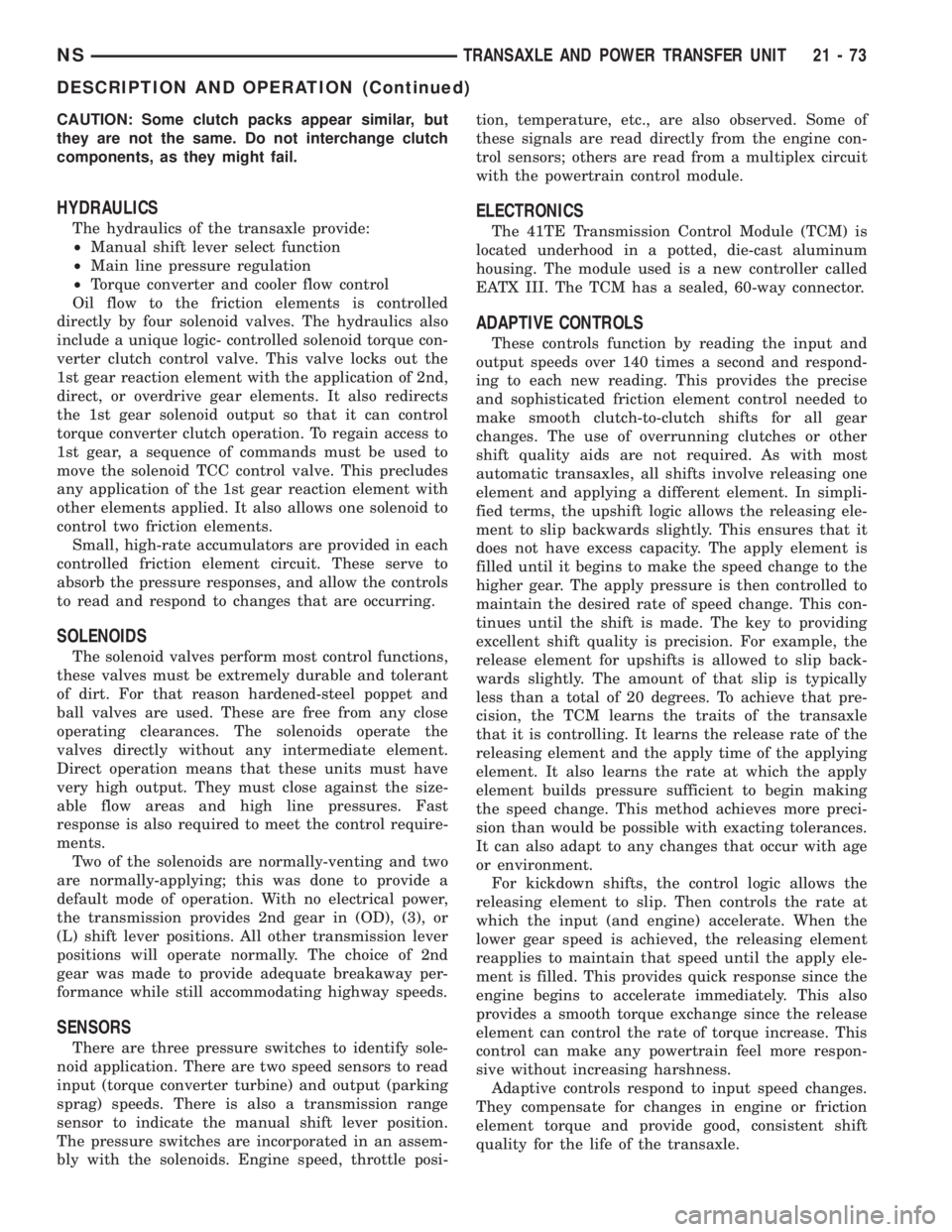
HYDRAULICS
The hydraulics of the transaxle provide:
²Manual shift lever select function
²Main line pressure regulation
²Torque converter and cooler flow control
Oil flow to the friction elements is controlled
directly by four solenoid valves. The hydraulics also
include a unique logic- controlled solenoid torque con-
verter clutch control valve. This valve locks out the
1st gear reaction element with the application of 2nd,
direct, or overdrive gear elements. It also redirects
the 1st gear solenoid output so that it can control
torque converter clutch operation. To regain access to
1st gear, a sequence of commands must be used to
move the solenoid TCC control valve. This precludes
any application of the 1st gear reaction element with
other elements applied. It also allows one solenoid to
control two friction elements.
Small, high-rate accumulators are provided in each
controlled friction element circuit. These serve to
absorb the pressure responses, and allow the controls
to read and respond to changes that are occurring.
SOLENOIDS
The solenoid valves perform most control functions,
these valves must be extremely durable and tolerant
of dirt. For that reason hardened-steel poppet and
ball valves are used. These are free from any close
operating clearances. The solenoids operate the
valves directly without any intermediate element.
Direct operation means that these units must have
very high output. They must close against the size-
able flow areas and high line pressures. Fast
response is also required to meet the control require-
ments.
Two of the solenoids are normally-venting and two
are normally-applying; this was done to provide a
default mode of operation. With no electrical power,
the transmission provides 2nd gear in (OD), (3), or
(L) shift lever positions. All other transmission lever
positions will operate normally. The choice of 2nd
gear was made to provide adequate breakaway per-
formance while still accommodating highway speeds.
SENSORS
There are three pressure switches to identify sole-
noid application. There are two speed sensors to read
input (torque converter turbine) and output (parking
sprag) speeds. There is also a transmission range
sensor to indicate the manual shift lever position.
The pressure switches are incorporated in an assem-
bly with the solenoids. Engine speed, throttle posi-tion, temperature, etc., are also observed. Some of
these signals are read directly from the engine con-
trol sensors; others are read from a multiplex circuit
with the powertrain control module.
ELECTRONICS
The 41TE Transmission Control Module (TCM) is
located underhood in a potted, die-cast aluminum
housing. The module used is a new controller called
EATX III. The TCM has a sealed, 60-way connector.
ADAPTIVE CONTROLS
These controls function by reading the input and
output speeds over 140 times a second and respond-
ing to each new reading. This provides the precise
and sophisticated friction element control needed to
make smooth clutch-to-clutch shifts for all gear
changes. The use of overrunning clutches or other
shift quality aids are not required. As with most
automatic transaxles, all shifts involve releasing one
element and applying a different element. In simpli-
fied terms, the upshift logic allows the releasing ele-
ment to slip backwards slightly. This ensures that it
does not have excess capacity. The apply element is
filled until it begins to make the speed change to the
higher gear. The apply pressure is then controlled to
maintain the desired rate of speed change. This con-
tinues until the shift is made. The key to providing
excellent shift quality is precision. For example, the
release element for upshifts is allowed to slip back-
wards slightly. The amount of that slip is typically
less than a total of 20 degrees. To achieve that pre-
cision, the TCM learns the traits of the transaxle
that it is controlling. It learns the release rate of the
releasing element and the apply time of the applying
element. It also learns the rate at which the apply
element builds pressure sufficient to begin making
the speed change. This method achieves more preci-
sion than would be possible with exacting tolerances.
It can also adapt to any changes that occur with age
or environment.
For kickdown shifts, the control logic allows the
releasing element to slip. Then controls the rate at
which the input (and engine) accelerate. When the
lower gear speed is achieved, the releasing element
reapplies to maintain that speed until the apply ele-
ment is filled. This provides quick response since the
engine begins to accelerate immediately. This also
provides a smooth torque exchange since the release
element can control the rate of torque increase. This
control can make any powertrain feel more respon-
sive without increasing harshness.
Adaptive controls respond to input speed changes.
They compensate for changes in engine or friction
element torque and provide good, consistent shift
quality for the life of the transaxle.
NSTRANSAXLE AND POWER TRANSFER UNIT 21 - 73
DESCRIPTION AND OPERATION (Continued)