1996 CHRYSLER VOYAGER clutch
[x] Cancel search: clutchPage 1232 of 1938
(28) Remove radiator support bolts.It is neces-
sary to loosen the receiver/dryer to gain access
to the radiator bolts.
(29) Remove radiator and fans as an assembly.
(30) Remove accessory drive belt generator/power
steering. Refer to Group 7, for procedure.
(31) Remove both power steering lines at pump,
and cap both lines.
NOTE: It is not necessary to discharge A/C system
for engine removal.
(32) Remove A/C compressor. Secure compressor
away from engine for clearance during engine
removal.
(33) Remove Generator and adjusting bracket.
NOTE: Do not remove the mounting base from the
generator. It is aligned at the factory and cannot be
realigned in the field.
(34) Hoist vehicle.
(35) Remove exhaust pipe at turbo outlet.
(36) Remove connections at starter.
(37) Remove power steering high pressure line
bracket at rear of oil pan.
(38) Remove both driveshafts from transaxle. Refer
to Group 2, Suspension and Driveshafts.
(39) Disconnect clutch cable at transaxle.
(40) Remove reinforcement plate on lower cross-
member.
(41) Remove front and rear engine mounts. Refer
to procedure outlined in this section.
(42) Drain engine oil and remove oil filter if neces-
sary.
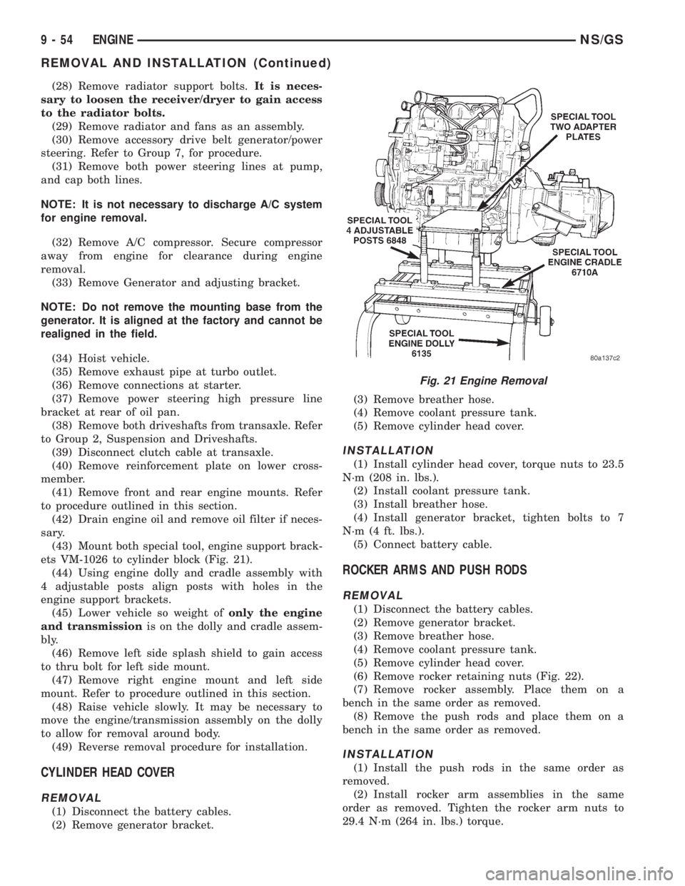
(43) Mount both special tool, engine support brack-
ets VM-1026 to cylinder block (Fig. 21).
(44) Using engine dolly and cradle assembly with
4 adjustable posts align posts with holes in the
engine support brackets.
(45) Lower vehicle so weight ofonly the engine
and transmissionis on the dolly and cradle assem-
bly.
(46) Remove left side splash shield to gain access
to thru bolt for left side mount.
(47) Remove right engine mount and left side
mount. Refer to procedure outlined in this section.
(48) Raise vehicle slowly. It may be necessary to
move the engine/transmission assembly on the dolly
to allow for removal around body.
(49) Reverse removal procedure for installation.
CYLINDER HEAD COVER
REMOVAL
(1) Disconnect the battery cables.
(2) Remove generator bracket.(3) Remove breather hose.
(4) Remove coolant pressure tank.
(5) Remove cylinder head cover.
INSTALLATION
(1) Install cylinder head cover, torque nuts to 23.5
N´m (208 in. lbs.).
(2) Install coolant pressure tank.
(3) Install breather hose.
(4) Install generator bracket, tighten bolts to 7
N´m (4 ft. lbs.).
(5) Connect battery cable.
ROCKER ARMS AND PUSH RODS
REMOVAL
(1) Disconnect the battery cables.
(2) Remove generator bracket.
(3) Remove breather hose.
(4) Remove coolant pressure tank.
(5) Remove cylinder head cover.
(6) Remove rocker retaining nuts (Fig. 22).
(7) Remove rocker assembly. Place them on a
bench in the same order as removed.
(8) Remove the push rods and place them on a
bench in the same order as removed.
INSTALLATION
(1) Install the push rods in the same order as
removed.
(2) Install rocker arm assemblies in the same
order as removed. Tighten the rocker arm nuts to
29.4 N´m (264 in. lbs.) torque.
Fig. 21 Engine Removal
9 - 54 ENGINENS/GS
REMOVAL AND INSTALLATION (Continued)
Page 1323 of 1938
FUEL INJECTION SYSTEM
INDEX
page page
GENERAL INFORMATION
INTRODUCTION......................... 30
MODES OF OPERATION.................. 30
DESCRIPTION AND OPERATION
AIR CONDITIONING (A/C) CLUTCH RELAYÐ
PCM OUTPUT......................... 41
AIR CONDITIONING PRESSURE
TRANSDUCERÐPCM INPUT............. 33
AIR CONDITIONING SWITCH SENSEÐ
PCM INPUT........................... 33
AUTOMATIC SHUTDOWN (ASD) SENSEÐ
PCM INPUT........................... 33
AUTOMATIC SHUTDOWN RELAYÐPCM
OUTPUT............................. 42
AUTOMATIC TRANSAXLE CONTROL
MODULEÐPCM OUTPUT................ 44
BATTERY VOLTAGEÐPCM INPUT........... 33
BRAKE SWITCHÐPCM INPUT.............. 33
CAMSHAFT POSITION SENSORÐPCM INPUT . 33
CCDBUS .............................. 32
CRANKSHAFT POSITION SENSORÐPCM
INPUT............................... 35
DATA LINK CONNECTORÐPCM OUTPUT..... 44
DUTY CYCLE EVAP CANISTER PURGE
SOLENOIDÐPCM OUTPUT.............. 43
ELECTRONIC EGR TRANSDUCER
SOLENOIDÐPCM OUTPUT.............. 43
ENGINE COOLANT TEMPERATURE SENSORÐ
PCM INPUT........................... 36
FUEL INJECTORSÐPCM OUTPUT.......... 44
FUEL PUMP RELAYÐPCM OUTPUT......... 42
GENERATOR FIELDÐPCM OUTPUT......... 42
HEATED OXYGEN SENSOR (O2S SENSOR)Ð
PCM INPUT........................... 37
IDLE AIR CONTROL MOTORÐPCM OUTPUT . . 42
IGNITION COILÐPCM OUTPUT............. 45
INTAKE AIR TEMPERATURE SENSORÐPCM
INPUT (2.4L ONLY)..................... 41
KNOCK SENSORÐPCM INPUT............. 38
MALFUNCTION INDICATOR (CHECK ENGINE)
LAMPÐPCM OUTPUT.................. 46
MANIFOLD ABSOLUTE PRESSURE (MAP)
SENSORÐPCM INPUT.................. 39
POWERTRAIN CONTROL MODULE (PCM).... 32
PROPORTIONAL PURGE SOLENOID......... 43
SOLID STATE FAN RELAYÐPCM OUTPUT.... 46
SPEED CONTROL SOLENOIDSÐ
PCM OUTPUT......................... 46
SPEED CONTROLÐPCM INPUT............ 39STARTER RELAYÐPCM OUTPUT........... 42
SYSTEM DIAGNOSIS..................... 32
TACHOMETERÐPCM OUTPUT............. 47
THROTTLE BODY....................... 47
THROTTLE POSITION SENSOR (TPS)Ð
PCM INPUT........................... 40
TORQUE CONVERTER CLUTCH SOLENOIDÐ
PCM OUTPUT......................... 46
TRANSAXLE PARK/NEUTRAL SWITCHÐ
PCM INPUT........................... 40
VEHICLE SPEED AND DISTANCEÐ
PCM INPUT........................... 41
DIAGNOSIS AND TESTING
ASD AND FUEL PUMP RELAYS............. 59
CAMSHAFT AND CRANKSHAFT POSITION
SENSOR............................. 61
ENGINE COOLANT TEMPERATURE SENSOR . . 61
HEATED OXYGEN SENSOR............... 61
KNOCK SENSOR........................ 61
MANIFOLD ABSOLUTE PRESSURE (MAP)
SENSOR............................. 60
THROTTLE BODY MINIMUM AIR FLOW
CHECK PROCEDURE................... 62
THROTTLE POSITION SENSOR............ 62
VISUAL INSPECTIONÐ2.4L ENGINE......... 47
VISUAL INSPECTIONÐ3.0L ENGINE......... 52
VISUAL INSPECTIONÐ3.3/3.8L ENGINES..... 55
REMOVAL AND INSTALLATION
AIR CLEANER ELEMENT.................. 70
AUTOMATIC SHUTDOWN (ASD) RELAY...... 64
CAMSHAFT POSITION SENSOR............ 68
CRANKSHAFT POSITION SENSOR.......... 68
DOWNSTREAM OXYGEN SENSOR.......... 69
ENGINE COOLANT TEMPERATURE
SENSORÐ2.4L........................ 70
ENGINE COOLANT TEMPERATURE
SENSORÐ3.0L........................ 71
ENGINE COOLANT TEMPERATURE
SENSORÐ3.3/3.8L..................... 71
FUEL PUMP RELAY...................... 64
IDLE AIR CONTROL MOTOR............... 65
INTAKE AIR TEMPERATURE SENSORÐ2.4L . . . 72
KNOCK SENSOR........................ 70
MANIFOLD ABSOLUTE PRESSURE (MAP)
SENSORÐ2.4/3.3/3.8L.................. 66
MANIFOLD ABSOLUTE PRESSURE (MAP)
SENSORÐ3.0L........................ 66
POWERTRAIN CONTROL MODULE.......... 67
PROPORTIONAL PURGE SOLENOID VALVE . . . 66
NSFUEL SYSTEM 14 - 29
Page 1326 of 1938
IGNITION SWITCH OFF MODE
When the ignition switch is turned to the OFF
position, the following occurs:
²All outputs are turned off.
²No inputs are monitored.
²The PCM shuts down.
DESCRIPTION AND OPERATION
SYSTEM DIAGNOSIS
The PCM can test many of its own input and out-
put circuits. If the PCM senses a fault in a major
system, the PCM stores a Diagnostic Trouble Code
(DTC) in memory.
For DTC information, refer to Group 25, Emission
Control Systems. See On-Board Diagnostics.
CCD BUS
Various controllers and modules exchange informa-
tion through a communications port called the CCD
Bus. The PCM transmits the malfunction indicator
(check engine) lamp On/Off signal, engine RPM and
vehicle load information on the CCD Bus.
POWERTRAIN CONTROL MODULE (PCM)
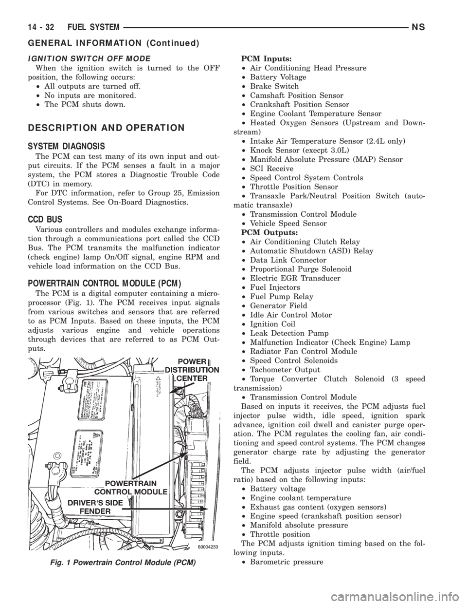
The PCM is a digital computer containing a micro-
processor (Fig. 1). The PCM receives input signals
from various switches and sensors that are referred
to as PCM Inputs. Based on these inputs, the PCM
adjusts various engine and vehicle operations
through devices that are referred to as PCM Out-
puts.PCM Inputs:
²Air Conditioning Head Pressure
²Battery Voltage
²Brake Switch
²Camshaft Position Sensor
²Crankshaft Position Sensor
²Engine Coolant Temperature Sensor
²Heated Oxygen Sensors (Upstream and Down-
stream)
²Intake Air Temperature Sensor (2.4L only)
²Knock Sensor (execpt 3.0L)
²Manifold Absolute Pressure (MAP) Sensor
²SCI Receive
²Speed Control System Controls
²Throttle Position Sensor
²Transaxle Park/Neutral Position Switch (auto-
matic transaxle)
²Transmission Control Module
²Vehicle Speed Sensor
PCM Outputs:
²Air Conditioning Clutch Relay
²Automatic Shutdown (ASD) Relay
²Data Link Connector
²Proportional Purge Solenoid
²Electric EGR Transducer
²Fuel Injectors
²Fuel Pump Relay
²Generator Field
²Idle Air Control Motor
²Ignition Coil
²Leak Detection Pump
²Malfunction Indicator (Check Engine) Lamp
²Radiator Fan Control Module
²Speed Control Solenoids
²Tachometer Output
²Torque Converter Clutch Solenoid (3 speed
transmission)
²Transmission Control Module
Based on inputs it receives, the PCM adjusts fuel
injector pulse width, idle speed, ignition spark
advance, ignition coil dwell and canister purge oper-
ation. The PCM regulates the cooling fan, air condi-
tioning and speed control systems. The PCM changes
generator charge rate by adjusting the generator
field.
The PCM adjusts injector pulse width (air/fuel
ratio) based on the following inputs:
²Battery voltage
²Engine coolant temperature
²Exhaust gas content (oxygen sensors)
²Engine speed (crankshaft position sensor)
²Manifold absolute pressure
²Throttle position
The PCM adjusts ignition timing based on the fol-
lowing inputs.
²Barometric pressure
Fig. 1 Powertrain Control Module (PCM)
14 - 32 FUEL SYSTEMNS
GENERAL INFORMATION (Continued)
Page 1327 of 1938
²Engine coolant temperature
²Engine speed (crankshaft position sensor)
²Intake air temperature (2.4L only)
²Manifold absolute pressure
²Throttle position
²Transaxle gear selection (park/neutral switch)
The PCM also adjusts engine idle speed through
the idle air control motor based on the following
inputs.
²Air conditioning select switch head pressure
²Brake switch
²Engine coolant temperature
²Engine speed (crankshaft position sensor)
²Manifold absolute pressure
²Throttle position
²Transaxle gear selection (park/neutral switch)
²Vehicle distance (speed)
The Automatic Shutdown (ASD) and fuel pump
relays are located in the Power Distribution Center
(PDC).
The camshaft position sensor (distributor pick-up
signal 3.0L) and crankshaft position sensor signals
are sent to the PCM. If the PCM does not receive
both signals within approximately one second of
engine cranking, it deactivates the ASD relay and
fuel pump relay. When these relays are deactivated,
power is shut off to the fuel injectors, ignition coil,
oxygen sensor heating element and fuel pump.
The PCM contains a voltage converter that
changes battery voltage to a regulated 8.0 volts to
power the camshaft position sensor, crankshaft posi-
tion sensor and vehicle speed sensor. The PCM also
provides a 5.0 volt supply for the manifold absolute
pressure sensor, throttle position sensor and engine
coolant temperature sensor.
AIR CONDITIONING PRESSURE TRANSDUCERÐ
PCM INPUT
The Powertrain Control Module (PCM) monitors
the A/C compressor discharge (high side) pressure
through the air conditioning pressure transducer.
The transducer supplies an input to the PCM. The
PCM engages the A/C compressor clutch if pressure
is sufficient for A/C system operation.
AIR CONDITIONING SWITCH SENSEÐPCM INPUT
When the air conditioning or defrost switch is put
in the ON position and the low pressure switch, com-
bination valve, and high pressure switch close, the
PCM receives an A/C input. After receiving this
input, the PCM activates the A/C compressor clutch
by grounding the A/C clutch relay. The PCM also
adjusts idle speed to a scheduled RPM to compensate
for increased engine load.
AUTOMATIC SHUTDOWN (ASD) SENSEÐPCM
INPUT
The ASD sense circuit informs the PCM when the
ASD relay energizes. A 12 volt signal at this input
indicates to the PCM that the ASD has been acti-
vated. This input is used only to sense that the ASD
relay is energized.
When energized, the ASD relay supplies battery
voltage to the fuel injectors, ignition coils and the
heating element in each oxygen sensor. If the PCM
does not receive 12 volts from this input after
grounding the ASD relay, it sets a Diagnostic Trouble
Code (DTC).
BATTERY VOLTAGEÐPCM INPUT
The PCM monitors the battery voltage input to
determine fuel injector pulse width and generator
field control.
If battery voltage is low the PCM will increase
injector pulse width (period of time that the injector
is energized).
BRAKE SWITCHÐPCM INPUT
When the brake switch is activated, the PCM
receives an input indicating that the brakes are
being applied. After receiving this input the PCM
maintains idle speed to a scheduled RPM through
control of the idle air control motor. The brake switch
is mounted on the brake pedal support bracket.
CAMSHAFT POSITION SENSORÐPCM INPUT
The PCM determines fuel injection synchronization
and cylinder identification from inputs provided by
the camshaft position sensor and crankshaft position
sensor. From the two inputs, the PCM determines
crankshaft position.
3.3/3.8L
The sensor generates pulses as groups of notches
on the camshaft sprocket pass underneath it (Fig. 2).
The PCM keeps track of crankshaft rotation and
identifies each cylinder by the pulses generated by
the notches on the camshaft sprocket. Four crank-
shaft pulses follow each group of camshaft pulses.
When the PCM receives two camshaft pulses fol-
lowed by the long flat spot on the camshaft sprocket,
it knows that the crankshaft timing marks for cylin-
der one are next (on driveplate). When the PCM
receives one camshaft pulse after the long flat spot
on the sprocket, cylinder number two crankshaft tim-
ing marks are next. After 3 camshaft pulses, the
PCM knows cylinder four crankshaft timing marks
follow. One camshaft pulse after the three pulses
indicates cylinder five. The two camshaft pulses after
cylinder 5 signals cylinder six (Fig. 3). The PCM can
synchronize on cylinders 1 or 4.
NSFUEL SYSTEM 14 - 33
DESCRIPTION AND OPERATION (Continued)
Page 1335 of 1938
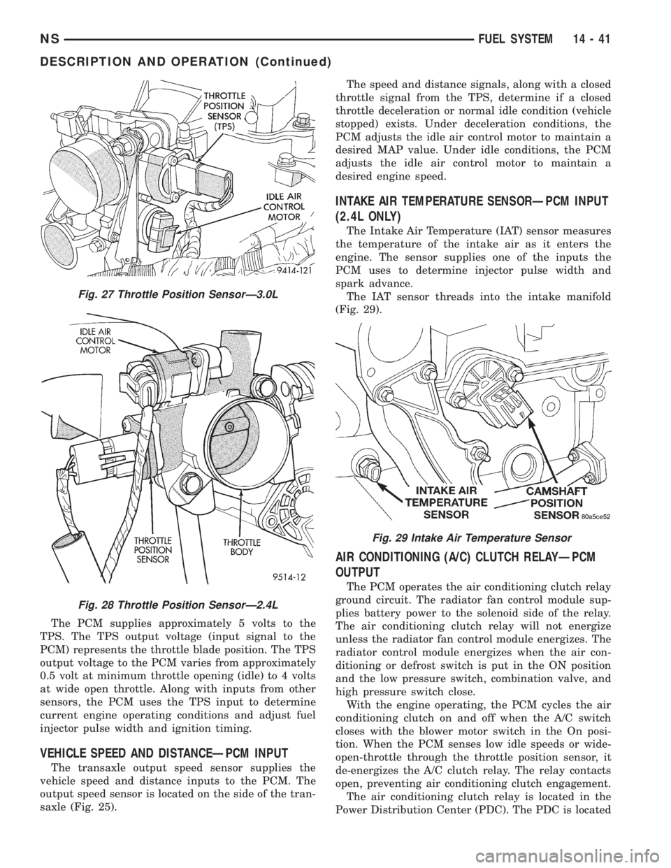
The PCM supplies approximately 5 volts to the
TPS. The TPS output voltage (input signal to the
PCM) represents the throttle blade position. The TPS
output voltage to the PCM varies from approximately
0.5 volt at minimum throttle opening (idle) to 4 volts
at wide open throttle. Along with inputs from other
sensors, the PCM uses the TPS input to determine
current engine operating conditions and adjust fuel
injector pulse width and ignition timing.
VEHICLE SPEED AND DISTANCEÐPCM INPUT
The transaxle output speed sensor supplies the
vehicle speed and distance inputs to the PCM. The
output speed sensor is located on the side of the tran-
saxle (Fig. 25).The speed and distance signals, along with a closed
throttle signal from the TPS, determine if a closed
throttle deceleration or normal idle condition (vehicle
stopped) exists. Under deceleration conditions, the
PCM adjusts the idle air control motor to maintain a
desired MAP value. Under idle conditions, the PCM
adjusts the idle air control motor to maintain a
desired engine speed.
INTAKE AIR TEMPERATURE SENSORÐPCM INPUT
(2.4L ONLY)
The Intake Air Temperature (IAT) sensor measures
the temperature of the intake air as it enters the
engine. The sensor supplies one of the inputs the
PCM uses to determine injector pulse width and
spark advance.
The IAT sensor threads into the intake manifold
(Fig. 29).
AIR CONDITIONING (A/C) CLUTCH RELAYÐPCM
OUTPUT
The PCM operates the air conditioning clutch relay
ground circuit. The radiator fan control module sup-
plies battery power to the solenoid side of the relay.
The air conditioning clutch relay will not energize
unless the radiator fan control module energizes. The
radiator control module energizes when the air con-
ditioning or defrost switch is put in the ON position
and the low pressure switch, combination valve, and
high pressure switch close.
With the engine operating, the PCM cycles the air
conditioning clutch on and off when the A/C switch
closes with the blower motor switch in the On posi-
tion. When the PCM senses low idle speeds or wide-
open-throttle through the throttle position sensor, it
de-energizes the A/C clutch relay. The relay contacts
open, preventing air conditioning clutch engagement.
The air conditioning clutch relay is located in the
Power Distribution Center (PDC). The PDC is located
Fig. 27 Throttle Position SensorÐ3.0L
Fig. 28 Throttle Position SensorÐ2.4L
Fig. 29 Intake Air Temperature Sensor
NSFUEL SYSTEM 14 - 41
DESCRIPTION AND OPERATION (Continued)
Page 1340 of 1938
Shutdown (ASD) RelayÐPCM Output in this section
for relay operation.
TORQUE CONVERTER CLUTCH SOLENOIDÐPCM
OUTPUT
Three-speed automatic transaxles use a torque con-
verter clutch solenoid. The PCM controls the engage-
ment of the torque converter clutch through the
solenoid. The torque converter clutch is engaged only
in direct drive mode. Refer to Group 21 for transaxle
information.
MALFUNCTION INDICATOR (CHECK ENGINE)
LAMPÐPCM OUTPUT
The PCM supplies the malfunction indicator (check
engine) lamp on/off signal to the instrument panel
through the CCD Bus. The CCD Bus is a communi-
cations port. Various modules use the CCD Bus to
exchange information.
The Check Engine lamp comes on each time the
ignition key is turned ON and stays on for 3 seconds
as a bulb test.
The Malfunction Indicator Lamp (MIL) stays on
continuously, when the PCM has entered a Limp-In
mode or identified a failed emission component. Dur-
ing Limp-in Mode, the PCM attempts to keep the
system operational. The MIL signals the need for
immediate service. In limp-in mode, the PCM com-
pensates for the failure of certain components that
send incorrect signals. The PCM substitutes for the
incorrect signals with inputs from other sensors.
If the PCM detects active engine misfire severe
enough to cause catalyst damage, it flashes the MIL.
At the same time the PCM also sets a Diagnostic
Trouble Code (DTC).
For signals that can trigger the MIL (Check
Engine Lamp) refer to Group 25, On-Board
Dianostics.
SOLID STATE FAN RELAYÐPCM OUTPUT
The radiator fan runs at a variable speed depend-
ing on coolant temperature and A/C system pressure.
The radiator fan circuit contains a Solid State Fan
Relay (SSFR). Refer to the Group 8W for a circuit
schematic.
A 5 volt signal is supplied to the SSFR. The PCM
provides a pulsed ground for the SSFR. Depending
upon the amount of pulse on time, the SSFR puts out
a proportional voltage to the fan motor at the lower
speed. For instance, if the on time is 30 percent, then
the voltage to the fan motor will be 3.6 volts.
When engine coolant reaches approximately 102ÉC
(215ÉF) the PCM grounds the SSFR relay. If engine
coolant reaches 207ÉC (225ÉF) the PCM grounds the
high speed ground relay and high speed fan relay. If
the fan operates at high speed, the PCM de-energizes
the high speed relay and high speed ground relay
when coolant temperature drops to approximately
101ÉC (214ÉF). When coolant temperature drops to
101ÉC (214ÉF) the fan operates at low speed. The
PCM de-energizes the low speed relay when coolant
temperature drops to approximately 93ÉC (199ÉF).
Also, when the air conditioning pressure switch
closes, the fan operates at high speed. The air condi-
tioning switch closes at 285 psi610 psi. When air
conditioning pressure drops approximately 40 psi, the
pressure switch opens and the fan operates at low
speed.
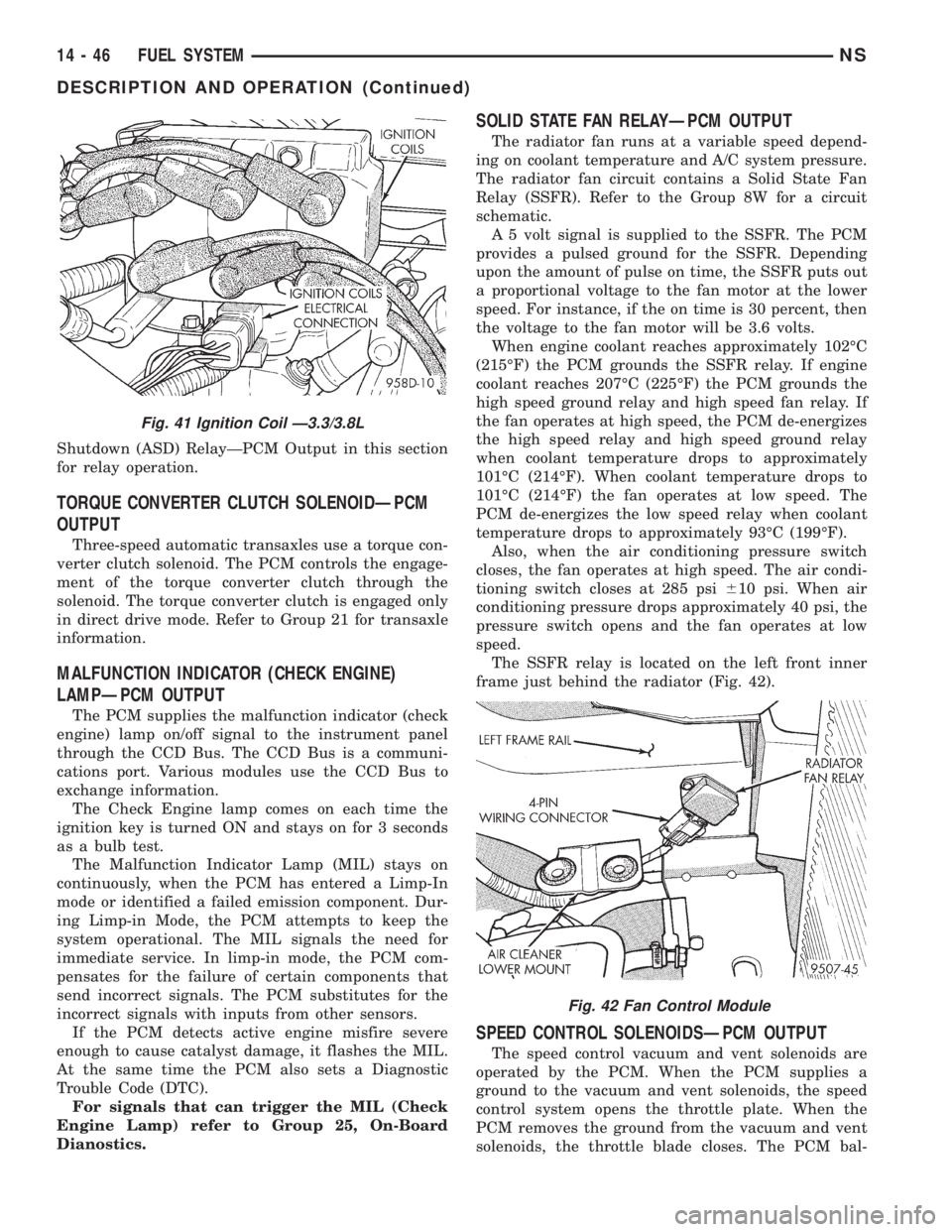
The SSFR relay is located on the left front inner
frame just behind the radiator (Fig. 42).
SPEED CONTROL SOLENOIDSÐPCM OUTPUT
The speed control vacuum and vent solenoids are
operated by the PCM. When the PCM supplies a
ground to the vacuum and vent solenoids, the speed
control system opens the throttle plate. When the
PCM removes the ground from the vacuum and vent
solenoids, the throttle blade closes. The PCM bal-
Fig. 41 Ignition Coil Ð3.3/3.8L
Fig. 42 Fan Control Module
14 - 46 FUEL SYSTEMNS
DESCRIPTION AND OPERATION (Continued)
Page 1388 of 1938
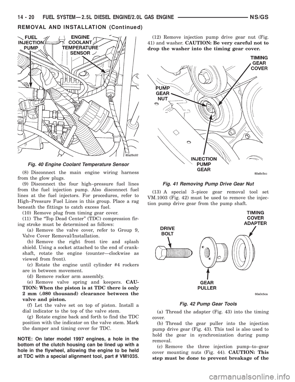
(8) Disconnect the main engine wiring harness
from the glow plugs.
(9) Disconnect the four high±pressure fuel lines
from the fuel injection pump. Also disconnect fuel
lines at the fuel injectors. For procedures, refer to
High±Pressure Fuel Lines in this group. Place a rag
beneath the fittings to catch excess fuel.
(10) Remove plug from timing gear cover.
(11) The ªTop Dead Centerº (TDC) compression fir-
ing stroke must be determined as follows:
(a) Remove the valve cover, refer to Group 9,
Valve Cover Removal/Installation.
(b) Remove the right front tire and splash
shield. Using a socket attached to the end of crank-
shaft, rotate the engine (counterÐclockwise as
viewed from front).
(c) Rotate the engine until cylinder #4 rockers
are in between movement.
(d) Remove rocker arm assembly.
(e) Remove valve spring and keepers.CAU-
TION: When the piston is at TDC there is only
2 mm (.080 thousand) clearance between the
valve and piston.
(f) Let the valve set on top of piston. Install a
dial indicator to the top of the valve stem.
(g) Rotate engine back and forth to find the TDC
position with the indicator on the valve stem. Mark
the damper and timing cover for TDC.
NOTE: On later model 1997 engines, a hole in the
bottom of the clutch housing can be lined up with a
hole in the flywheel, allowing the engine to be held
at TDC with a special alignment tool, part # VM1035.(12) Remove injection pump drive gear nut (Fig.
41) and washer.CAUTION: Be very careful not to
drop the washer into the timing gear cover.
(13) A special 3±piece gear removal tool set
VM.1003 (Fig. 42) must be used to remove the injec-
tion pump drive gear from the pump shaft.
(a) Thread the adapter (Fig. 43) into the timing
cover.
(b) Thread the gear puller into the injection
pump drive gear (Fig. 43). This tool is also used to
hold the gear in synchronization during pump
removal.
(c) Remove the three injection pump±to±gear
cover mounting nuts (Fig. 44).CAUTION: This
step must be done to prevent breakage of the
Fig. 40 Engine Coolant Temperature Sensor
Fig. 41 Removing Pump Drive Gear Nut
Fig. 42 Pump Gear Tools
14 - 20 FUEL SYSTEMÐ2.5L DIESEL ENGINE/2.0L GAS ENGINENS/GS
REMOVAL AND INSTALLATION (Continued)
Page 1411 of 1938
FUEL INJECTION SYSTEMÐ2.5L DIESEL ENGINE
INDEX
page page
GENERAL INFORMATION
INTRODUCTION....................... 43
DESCRIPTION AND OPERATION
AIR CONDITIONING (A/C) CONTROLSÐ
PCM INPUTS........................ 47
AIR CONDITIONING RELAYÐPCM OUTPUT . . 48
BATTERY VOLTAGEÐPCM INPUT.......... 45
BOOST PRESSURE SENSOR............. 45
BRAKE SWITCHÐPCM INPUT............. 47
DATA LINK CONNECTORÐ
PCM INPUT AND OUTPUT.............. 47
DIESEL PCM RELAYÐPCM INPUT......... 48
ENGINE COOLANT GAUGEÐPCM OUTPUT . . 48
ENGINE COOLANT TEMPERATURE SENSORÐ
PCM INPUT......................... 46
ENGINE OIL PRESSURE GAUGEÐ
PCM OUTPUT........................ 48
ENGINE SPEED SENSORÐPCM INPUT..... 46
EXHAUST GAS RECIRCULATION (EGR)
SOLENOIDÐPCM OUTPUT............. 50
FIVE VOLT POWERÐPCM OUTPUT........ 48
FUEL INJECTOR SENSORÐGROUND...... 46
FUEL TIMING SOLENOIDÐPCM OUTPUT.... 48
GLOW PLUG LAMPÐPCM OUTPUT........ 48
GLOW PLUG RELAYÐPCM OUTPUT....... 49
GLOW PLUGS......................... 49
IGNITION CIRCUIT SENSEÐPCM INPUT.... 45
NEEDLE MOVEMENT OR INSTRUMENTED
FIRST INJECTORÐPCM INPUT.......... 45
POWER GROUND...................... 45
POWERTRAIN CONTROL MODULE (PCM) . . . 44
SENSOR RETURNÐPCM INPUT (ANALOG
GROUND)........................... 45SIGNAL GROUNDÐPCM INPUT........... 45
SPEED CONTROLÐPCM INPUTS.......... 48
SPEED CONTROLÐPCM OUTPUTS........ 48
START SIGNALÐPCM INPUT............. 45
TACHOMETERÐPCM OUTPUT............ 49
VEHICLE SPEED SENSORÐPCM INPUT.... 47
VEHICLE THEFT ALARM................. 45
DIAGNOSIS AND TESTING
BOOST PRESSURE SENSOR............. 53
DIAGNOSTIC TROUBLE CODES........... 53
DIESEL DIAGNOSTICS.................. 50
DIESEL PCM RELAY TEST............... 50
ENGINE COOLANT TEMPERATURE
SENSOR TEST....................... 50
ENGINE SPEED SENSOR TEST........... 50
GLOW PLUG RELAY TEST............... 51
GLOW PLUG TEST..................... 51
RELAYSÐOPERATION/TESTING........... 52
VEHICLE SPEED SENSOR TEST........... 53
REMOVAL AND INSTALLATION
A/C CLUTCH RELAY.................... 53
DIESEL PCM RELAY.................... 53
ENGINE COOLANT TEMPERATURE
SENSOR............................ 54
ENGINE SPEED SENSOR................ 53
GLOW PLUG RELAY.................... 55
GLOW PLUGS......................... 54
POWERTRAIN CONTROL MODULE (PCM) . . . 55
VEHICLE SPEED SENSOR............... 55
SPECIFICATIONS
GLOW PLUG CURRENT DRAW............ 56
TORQUE CHARTÐ2.5L DIESEL............ 57
GENERAL INFORMATION
INTRODUCTION
This section will cover components either regulated
or controlled by the Powertrain Control Module
(PCM). The fuel heater relay, fuel heater and fuel
gauge are not operated by the PCM. These compo-
nents are controlled by the ignition (key) switch. All
other fuel system electrical components necessary to
operate the engine are controlled or regulated by the
PCM. Refer to the following PCM description for
more information.
Certain fuel system component failures may cause
a no start, or prevent the engine from running. It is
important to know that the PCM has a featurewhere, if possible, it will ignore the failed sensor, set
a code related to the sensor, and operate the engine
in a ªLimp Homeº mode. When the PCM is operating
in a ªLimp Homeº mode, the Diesel Glow Plug lamp
on the instrument panel will be constantly illumi-
nated, and the engine will most likely have a notice-
able loss of performance. An example of this would be
an Accelerator Pedal Position Sensor failure, and in
that situation, the engine would run at a constant
1100 RPM, regardless of the actual position of the
pedal. This is the most extreme of the three ªLimp
Homeº modes.
In addition to indicating that the glow plugs are
hot enough to start combustion, the Glow Plug Lamp
is also used in the diagnosis of the PCM, and when
NS/GSFUEL SYSTEMÐ2.5L DIESEL ENGINE/2.0L GAS ENGINE 14 - 43