1996 ACURA RL KA9 check engine
[x] Cancel search: check enginePage 1196 of 1954
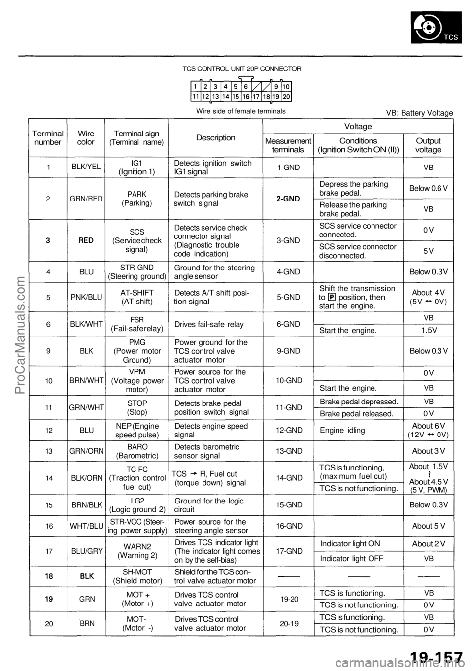
TCS CONTROL UNIT 20P CONNECTOR
Wire side of female terminals
VB: Battery Voltage
Terminal
number
1
2
4
5
6
9
10
11
12
13
14
15
16
17
20
Wire
color
BLK/YEL
GRN/RED
BLU
PNK/BLU
BLK/WHT
BLK
BRN/WHT
GRN/WHT
BLU
GRN/ORN
BLK/ORN
BRN/BLK
WHT/BLU
BLU/GRY
GRN
BRN
Terminal sign
(Terminal name)
IG1
(Ignition 1)
PARK
(Parking)
SCS
(Service check
signal)
STR-GND
(Steering ground)
AT-SHIFT
(AT shift)
FSR
(Fail-safe relay)
PMG
(Power motor
Ground)
VPM
(Voltage power
motor)
STOP
(Stop)
NEP (Engine
speed pulse)
BARO
(Barometric)
TC-FC
(Traction control
fuel cut)
LG2
(Logic ground 2)
STR-VCC (Steer-
ing power supply)
WARN2
(Warning 2)
SH-MOT
(Shield motor)
MOT +
(Motor +)
MOT-
(Motor -)
Description
Detects ignition switch
IG1 signal
Detects parking brake
switch signal
Detects service check
connector signal
(Diagnostic trouble
code indication)
Ground for the steering
angle sensor
Detects A/T shift posi-
tion signal
Drives fail-safe relay
Power ground for the
TCS control valve
actuator motor
Power source for the
TCS control valve
actuator motor
Detects brake pedal
position switch signal
Detects engine speed
signal
Detects barometric
sensor signal
TCS Fl, Fuel cut
(torque down) signal
Ground for the logic
circuit
Power source for the
steering angle sensor
Drives TCS indicator light
(The indicator light comes
on by the self-bias)
Shield for the TCS con-
trol valve actuator motor
Drives TCS control
valve actuator motor
Drives TCS control
valve actuator motor
Measurement
terminals
1-GND
2
3-GND
4-GND
5-GND
6-GND
9-GND
10-GND
11-GND
12-GND
13-GND
14-GND
15-GND
16-GND
17-GND
19-20
20-19
Voltage
Conditions
(Ignition Switch ON (II))
Depress the parking
brake pedal.
Release the parking
brake pedal.
SCS service connector
connected.
SCS service connector
disconnected.
Shift the transmission
to position, then
start the engine.
Start the engine.
Start the engine.
Brake pedal depressed.
Brake pedal released.
Engine idling
TCS is functioning,
(maximum fuel cut)
TCS is not functioning.
Indicator light ON
Indicator light OFF
TCS is functioning.
TCS is not functioning.
TCS is functioning.
TCS is not functioning.
Output
voltage
VB
Below 0.6 V
VB
0V
5V
Below 0.3V
About 4V
(5V 0V)
VB
1.5V
Below 0.3 V
0V
VB
VB
0V
About 6V
(12V
0V)
About 3 V
About 1.5V
About 4.5 V
(5 V,
PWM)
Below 0.3V
About 5 V
About 2 V
VB
VB
0V
VB
0VProCarManuals.com
Page 1211 of 1954
Troubleshooting
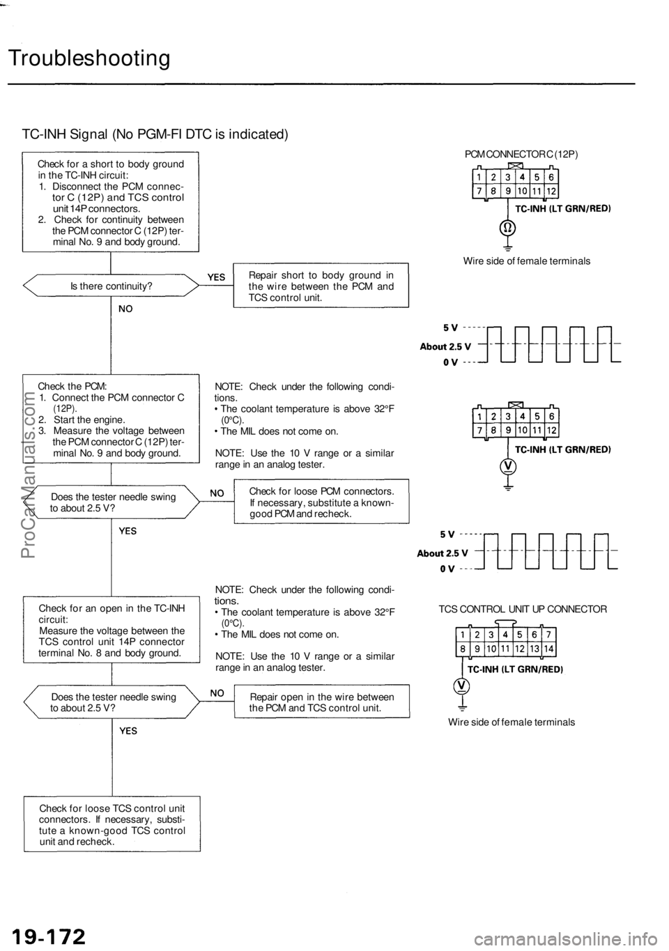
TC-INH Signal (No PGM-FI DTC is indicated)
Check for a short to body ground
in the TC-INH circuit:
1. Disconnect the PCM connec-
tor C (12P) and TCS control
unit 14P connectors.
2. Check for continuity between
the PCM connector C (12P) ter-
minal No. 9 and body ground.
Is there continuity?
Check the PCM:
1. Connect the PCM connector C
(12P).
2. Start the engine.
3. Measure the voltage between
the PCM connector C (12P) ter-
minal No. 9 and body ground.
Does the tester needle swing
to about 2.5 V?
Check for an open in the TC-INH
circuit:
Measure the voltage between the
TCS control unit 14P connector
terminal No. 8 and body ground.
Does the tester needle swing
to about 2.5 V?
Check for loose TCS control unit
connectors. If necessary, substi-
tute a known-good TCS control
unit and recheck.
PCM CONNECTOR C (12P)
Repair short to body ground in
the wire between the PCM and
TCS control unit.
Wire side of female terminals
NOTE: Check under the following condi-
tions.
The coolant temperature is above 32°F
(0°C).
The MIL does not come on.
NOTE: Use the 10 V range or a similar
range in an analog tester.
Check for loose PCM connectors.
If necessary, substitute a known-
good PCM and recheck.
NOTE: Check under the following condi-
tions.
The coolant temperature is above 32°F
(0°C).
The MIL does not come on.
NOTE: Use the 10 V range or a similar
range in an analog tester.
TCS CONTROL UNIT UP CONNECTOR
Repair open in the wire between
the PCM and TCS control unit.
Wire side of female terminalsProCarManuals.com
Page 1212 of 1954
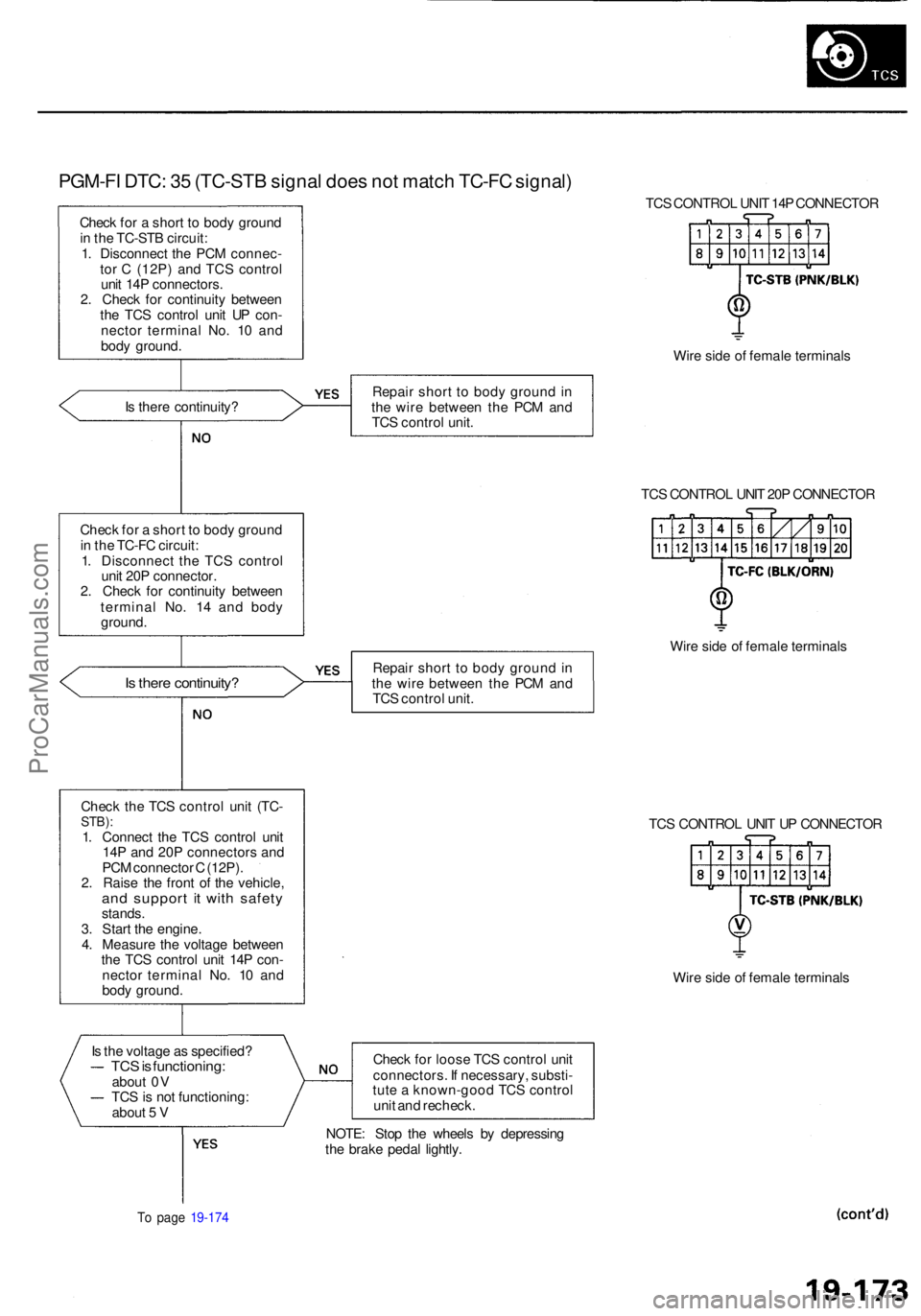
PGM-FI DTC : 3 5 (TC-ST B signa l doe s no t matc h TC-F C signal )
Check fo r a shor t t o bod y groun d
i n th e TC-ST B circuit :
1 . Disconnec t th e PC M connec -
to r C (12P ) an d TC S contro l
uni t 14 P connectors .
2 . Chec k fo r continuit y betwee n
th e TC S contro l uni t U P con -
necto r termina l No . 1 0 an d
bod y ground . TC
S CONTRO L UNI T 14 P CONNECTO R
Wir e sid e o f femal e terminal s
I s ther e continuity ? Repai
r shor t t o bod y groun d in
th e wir e betwee n th e PC M an d
TC S contro l unit .
TCS CONTRO L UNI T 20 P CONNECTO R
Chec k fo r a shor t t o bod y groun d
i n th e TC-F C circuit :
1 . Disconnec t th e TC S contro l
uni t 20 P connector .
2 . Chec k fo r continuit y betwee n
termina l No . 1 4 an d bod y
ground .
Is ther e continuity ?Repair shor t t o bod y groun d in
th e wir e betwee n th e PC M an d
TC S contro l unit . Wir
e sid e o f femal e terminal s
Chec k th e TC S contro l uni t (TC -
STB) :1. Connec t th e TC S contro l uni t
14 P an d 20 P connector s an d
PC M connecto r C (12P) .
2 . Rais e th e fron t o f th e vehicle ,
and suppor t i t wit h safet ystands.
3 . Star t th e engine .
4 . Measur e th e voltag e betwee n
th e TC S contro l uni t 14 P con -
necto r termina l No . 1 0 an d
bod y ground . TC
S CONTRO L UNI T U P CONNECTO R
Wir e sid e o f femal e terminal s
I s th e voltag e a s specified ?
TCS is functioning :about 0 V
TC S is no t functioning :
abou t 5 V Chec
k fo r loos e TC S contro l uni t
connectors . I f necessary , substi -
tut e a known-goo d TC S contro l
uni t an d recheck .
To pag e 19-17 4
NOTE : Sto p th e wheel s b y depressin g
th e brak e peda l lightly .
ProCarManuals.com
Page 1215 of 1954
Troubleshooting
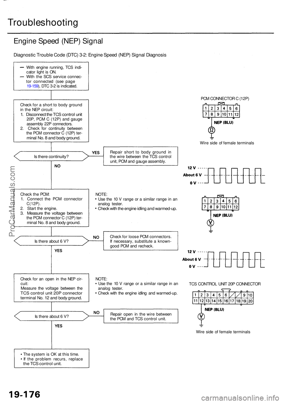
Engine Spee d (NEP ) Signa l
Diagnosti c Troubl e Cod e (DTC ) 3-2 : Engin e Spee d (NEP ) Signa l Diagnosi s
With engin e running , TC S indi -
cato r ligh t i s ON .
Wit h th e SC S servic e connec -
to r connecte d (se e pag e
19-159 ), DT C 3- 2 is indicated .
Chec k fo r a shor t t o bod y groun d
i n th e NE P circuit :
1. Disconnec t th e TC S contro l uni t20P , PC M C (12P ) an d gaug e
assembl y 22 P connectors .
2 . Chec k fo r continuit y betwee n
th e PC M connecto r C (12P ) ter -
mina l No . 8 an d bod y ground .
Is ther e continuity ?
Is ther e abou t 6 V ?
Chec k fo r a n ope n in th e NE P cir -
cuit :
Measur e th e voltag e betwee n th e
TC S contro l uni t 20 P connecto rterminal No . 1 2 an d bod y ground .
Is ther e abou t 6 V ?
Th e syste m is O K a t thi s time .
I f th e proble m recurs , replac e
the TC S contro l unit .
PCM CONNECTO R C (12P )
Wir e sid e o f femal e terminal s
Repai r shor t t o bod y groun d i n
th e wir e betwee n th e TC S contro l
unit , PC M an d gaug e assembly .
Chec k fo r loos e PC M connectors .
I f necessary , substitut e a known -
goo d PC M an d recheck .
NOTE :
Us e th e 1 0 V rang e o r a simila r rang e in a n
analo g tester .
Chec k wit h th e engin e idlin g an d warmed-up .TC
S CONTRO L UNI T 20 P CONNECTO R
Repai r ope n in th e wir e betwee n
th e PC M an d TC S contro l unit .
Wire sid e o f femal e terminal s
Chec
k th e PCM :
1 . Connec t th e PC M connecto r
C(12P).2. Star t th e engine .3. Measur e th e voltag e betwee nthe PC M connecto r C (12P ) ter -mina l No . 8 an d bod y ground .
Use th e 1 0 V rang e o r a simila r rang e in a n
analo g tester .
Check wit h th e engin e idlin g an d warmed-up .
NOTE:
ProCarManuals.com
Page 1226 of 1954
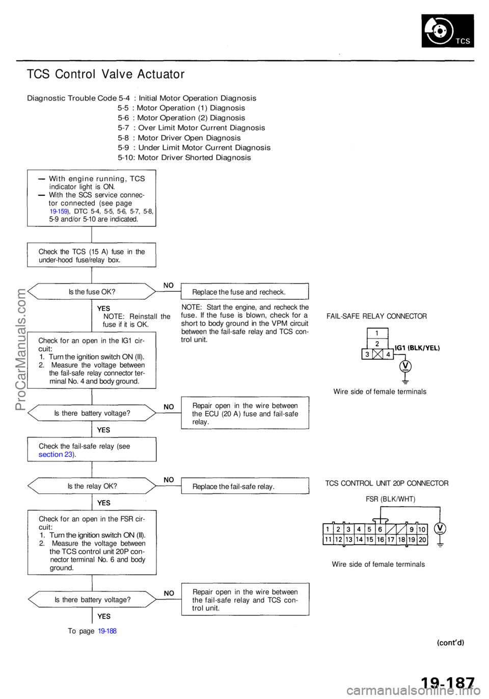
TCS Contro l Valv e Actuato r
Diagnosti c Troubl e Cod e 5- 4 : Initia l Moto r Operatio n Diagnosi s
5-5 : Moto r Operatio n (1 ) Diagnosi s
5-6 : Moto r Operatio n (2 ) Diagnosi s
5-7 : Ove r Limi t Moto r Curren t Diagnosi s
5-8 : Moto r Drive r Ope n Diagnosi s
5-9 : Unde r Limi t Moto r Curren t Diagnosi s
5-10: Moto r Drive r Shorte d Diagnosi s
With engin e running , TC Sindicato r ligh t i s ON .
Wit h th e SC S servic e connec -
to r connecte d (se e pag e
19-159 ), DT C 5-4 , 5-5 , 5-6 , 5-7 , 5-8 ,5-9 and/o r 5-1 0 ar e indicated .
Chec k th e TC S (1 5 A ) fus e i n th e
under-hoo d fuse/rela y box .
I s th e fus e OK ?
Replace th e fus e an d recheck .
NOTE : Reinstal l th e
fus e i f i t i s OK .
Chec k fo r a n ope n i n th e IG 1 cir -
cuit:1. Tur n th e ignitio n switc h O N (II) .2. Measur e th e voltag e betwee n
th e fail-saf e rela y connecto r ter -
mina l No . 4 an d bod y ground .
NOTE: Star t th e engine , an d rechec k th efuse . I f th e fus e i s blown , chec k fo r ashor t t o bod y groun d in th e VP M circui tbetwee n th e fail-saf e rela y an d TC S con -trol unit .
FAIL-SAF E RELA Y CONNECTO R
Wire sid e o f femal e terminal s
I s ther e batter y voltage ? Repai
r ope n i n th e wir e betwee n
th e EC U (2 0 A ) fus e an d fail-saf e
relay .
Chec k th e fail-saf e rela y (se e
sectio n 23).
I s th e rela y OK ?
Replac e th e fail-saf e relay .TCS CONTRO L UNI T 20 P CONNECTO R
FSR (BLK/WHT )
Check fo r a n ope n in th e FS R cir -cuit :1. Tur n th e ignitio n switc h O N (II) .2. Measur e th e voltag e betwee nthe TC S contro l uni t 20 P con -necto r termina l No . 6 an d bod yground .Wire sid e o f femal e terminal s
I s ther e batter y voltage ?
T o pag e 19-18 8 Repai
r ope n i n th e wir e betwee n
th e fail-saf e rela y an d TC S con -
trol unit .
ProCarManuals.com
Page 1230 of 1954
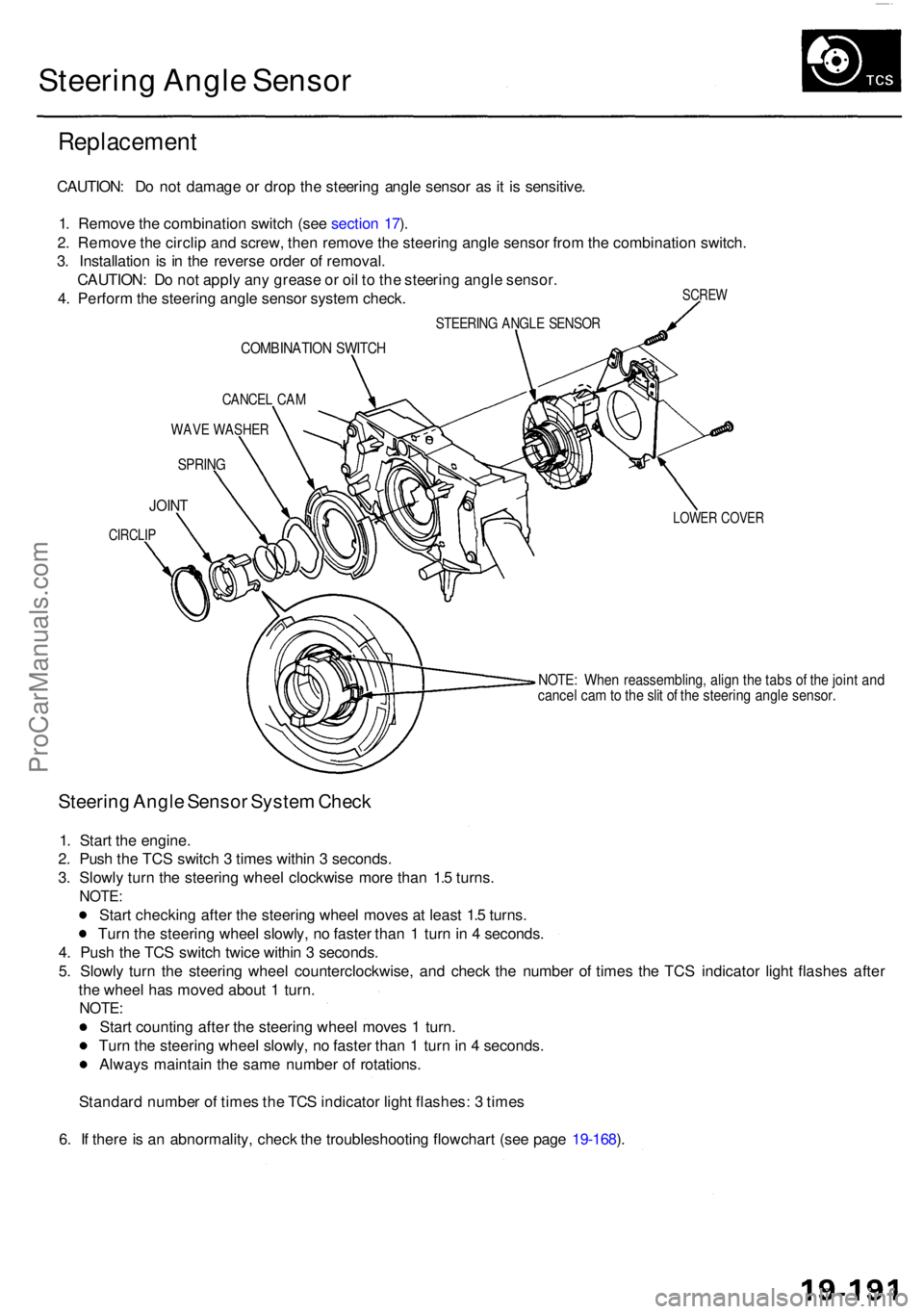
Steering Angl e Senso r
Replacemen t
SCREW
CAUTION : D o no t damag e o r dro p th e steerin g angl e senso r a s it i s sensitive .
1 . Remov e th e combinatio n switc h (se e sectio n 17 ).
2 . Remov e th e circli p an d screw , the n remov e th e steerin g angl e senso r fro m th e combinatio n switch .
3 . Installatio n i s i n th e revers e orde r o f removal .
CAUTION : D o no t appl y an y greas e o r oi l t o th e steerin g angl e sensor .
4 . Perfor m th e steerin g angl e senso r syste m check .
STEERIN G ANGL E SENSO R
COMBINATIO N SWITC H
CANCE L CA M
WAV E WASHE R
SPRING
LOWER COVE RJOINT
CIRCLI P
NOTE: Whe n reassembling , alig n th e tab s o f th e join t an dcance l ca m to th e sli t o f th e steerin g angl e sensor .
Steering Angl e Senso r Syste m Chec k
1. Star t th e engine .
2 . Pus h th e TC S switc h 3 time s withi n 3 seconds .
3 . Slowl y tur n th e steerin g whee l clockwis e mor e tha n 1. 5 turns .
NOTE :
Start checkin g afte r th e steerin g whee l move s a t leas t 1. 5 turns .
Tur n th e steerin g whee l slowly , n o faste r tha n 1 tur n in 4 seconds .
4 . Pus h th e TC S switc h twic e withi n 3 seconds .
5 . Slowl y tur n th e steerin g whee l counterclockwise , an d chec k th e numbe r o f time s th e TC S indicato r ligh t flashe s afte r
th e whee l ha s move d abou t 1 turn .
NOTE :
Start countin g afte r th e steerin g whee l move s 1 turn .
Tur n th e steerin g whee l slowly , n o faste r tha n 1 tur n in 4 seconds .
Alway s maintai n th e sam e numbe r o f rotations .
Standar d numbe r o f time s th e TC S indicato r ligh t flashes : 3 time s
6 . I f ther e is a n abnormality , chec k th e troubleshootin g flowchar t (se e pag e 19-168 ).
ProCarManuals.com
Page 1239 of 1954
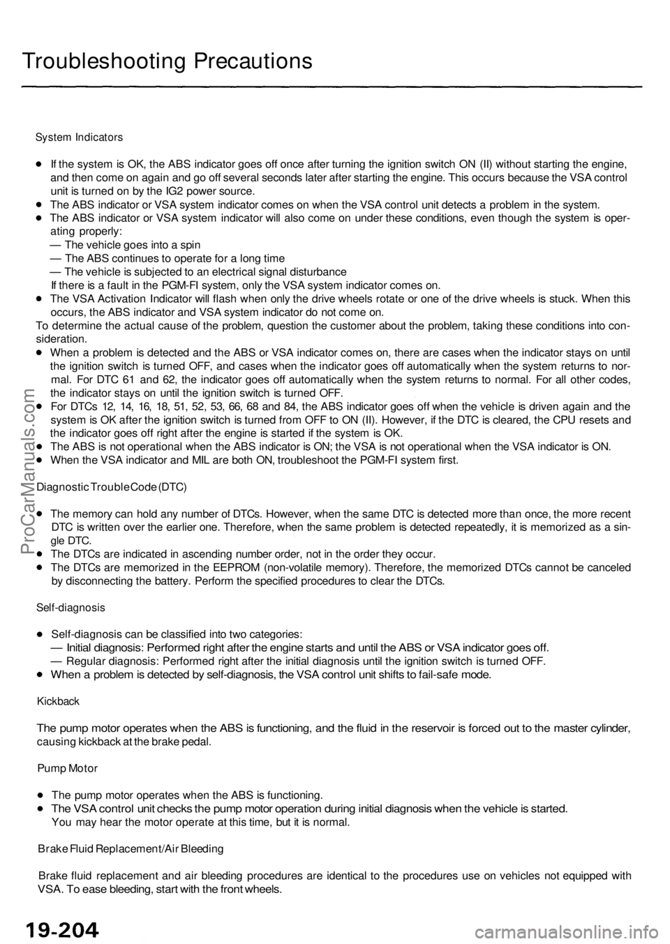
Troubleshooting Precaution s
System Indicator s
If th e syste m is OK , th e AB S indicato r goe s of f onc e afte r turnin g th e ignitio n switc h O N (II ) withou t startin g th e engine ,
an d the n com e o n agai n an d g o of f severa l second s late r afte r startin g th e engine . Thi s occur s becaus e th e VS A contro l
uni t i s turne d o n b y th e IG 2 powe r source .
Th e AB S indicato r o r VS A syste m indicato r come s o n whe n th e VS A contro l uni t detect s a proble m in th e system .
Th e AB S indicato r o r VS A syste m indicato r wil l als o com e o n unde r thes e conditions , eve n thoug h th e syste m is oper -
atin g properly :
— Th e vehicl e goe s int o a spi n
— Th e AB S continue s t o operat e fo r a lon g tim e
— Th e vehicl e is subjecte d to a n electrica l signa l disturbanc e
I f ther e is a faul t i n th e PGM-F I system , onl y th e VS A syste m indicato r come s on .
Th e VS A Activatio n Indicato r wil l flas h whe n onl y th e driv e wheel s rotat e o r on e o f th e driv e wheel s is stuck . Whe n thi s
occurs , th e AB S indicato r an d VS A syste m indicato r d o no t com e on .
T o determin e th e actua l caus e o f th e problem , questio n th e custome r abou t th e problem , takin g thes e condition s int o con -
sideration .
Whe n a proble m is detecte d an d th e AB S o r VS A indicato r come s on , ther e ar e case s whe n th e indicato r stay s o n unti l
th e ignitio n switc h i s turne d OFF , an d case s whe n th e indicato r goe s of f automaticall y whe n th e syste m return s t o nor -
mal . Fo r DT C 6 1 an d 62 , th e indicato r goe s of f automaticall y whe n th e syste m return s t o normal . Fo r al l othe r codes ,
th e indicato r stay s o n unti l th e ignitio n switc h is turne d OFF .
Fo r DTC s 12 , 14 , 16 , 18 , 51 , 52 , 53 , 66 , 6 8 an d 84 , th e AB S indicato r goe s of f whe n th e vehicl e is drive n agai n an d th e
syste m is O K afte r th e ignitio n switc h is turne d fro m OF F to O N (II) . However , i f th e DT C is cleared , th e CP U reset s an d
th e indicato r goe s of f righ t afte r th e engin e is starte d if th e syste m is OK .
Th e AB S is no t operationa l whe n th e AB S indicato r i s ON ; th e VS A is no t operationa l whe n th e VS A indicato r i s ON .
Whe n th e VS A indicato r an d MI L ar e bot h ON , troubleshoo t th e PGM-F I syste m first .
Diagnosti c Troubl e Cod e (DTC )
Th e memor y ca n hol d an y numbe r o f DTCs . However , whe n th e sam e DT C is detecte d mor e tha n once , th e mor e recen t
DT C is writte n ove r th e earlie r one . Therefore , whe n th e sam e proble m is detecte d repeatedly , i t i s memorize d a s a sin -
gle DTC .
The DTC s ar e indicate d in ascendin g numbe r order , no t i n th e orde r the y occur .
Th e DTC s ar e memorize d in th e EEPRO M (non-volatil e memory) . Therefore , th e memorize d DTC s canno t b e cancele d
b y disconnectin g th e battery . Perfor m th e specifie d procedure s to clea r th e DTCs .
Self-diagnosi s
Self-diagnosis can be classifie d int o tw o categories :
— Initia l diagnosis : Performe d righ t afte r th e engin e start s an d unti l th e AB S o r VS A indicato r goe s off .
— Regula r diagnosis : Performe d righ t afte r th e initia l diagnosi s unti l th e ignitio n switc h is turne d OFF .
When a proble m is detecte d b y self-diagnosis , th e VS A contro l uni t shift s to fail-saf e mode .
Kickbac k
The pum p moto r operate s whe n th e AB S is functioning , an d th e flui d in th e reservoi r i s force d ou t t o th e maste r cylinder ,
causing kickbac k a t th e brak e pedal .
Pum p Moto r
Th e pum p moto r operate s whe n th e AB S is functioning .
The VS A contro l uni t check s th e pum p moto r operatio n durin g initia l diagnosi s whe n th e vehicl e is started .
You ma y hea r th e moto r operat e a t thi s time , bu t i t i s normal .
Brak e Flui d Replacement/Ai r Bleedin g
Brak e flui d replacemen t an d ai r bleedin g procedure s ar e identica l t o th e procedure s us e o n vehicle s no t equippe d wit h
VSA . T o eas e bleeding , star t wit h th e fron t wheels .
ProCarManuals.com
Page 1256 of 1954
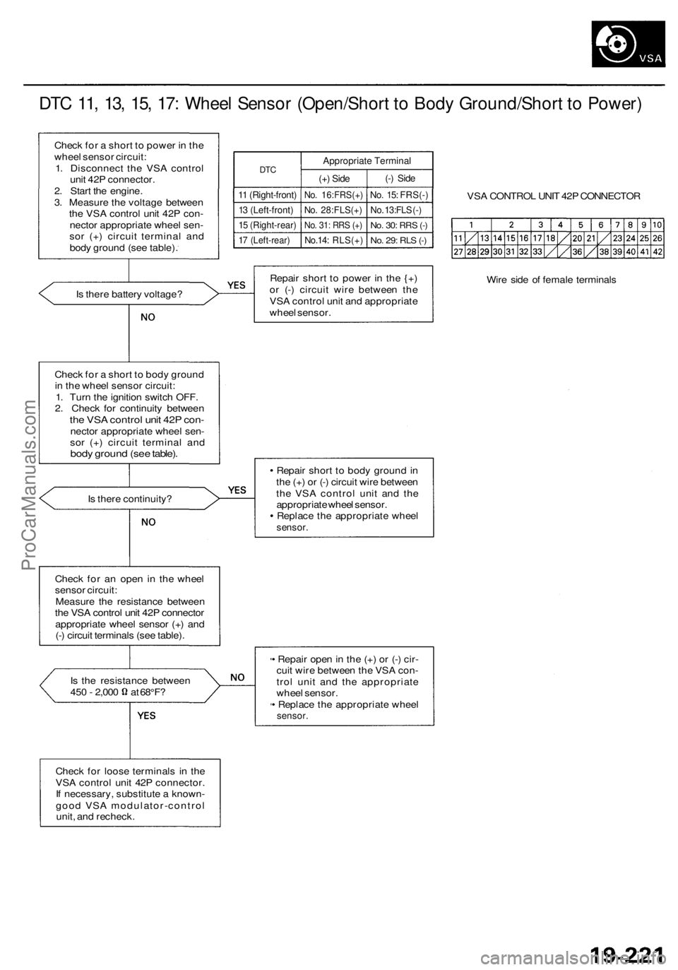
DTC 11, 13, 15, 17: Wheel Sensor (Open/Short to Body Ground/Short to Power)
Check for a short to power in the
wheel sensor circuit:
1. Disconnect the VSA control
unit 42P connector.
2. Start the engine.
3. Measure the voltage between
the VSA control unit 42P con-
nector appropriate wheel sen-
sor (+) circuit terminal and
body ground (see table).
DTC
11 (Right-front)
13 (Left-front)
15 (Right-rear)
17 (Left-rear)
Appropriate Terminal
(+) Side
No. 16:FRS(+)
No. 28:FLS(+)
No. 31: RRS (+)
No.14: RLS(+)
(-) Side
No. 15: FRS(-)
No. 13:FLS (-)
No. 30:
RRS
(-)
No. 29: RLS (-)
VSA CONTROL UNIT 42P CONNECTOR
Is there battery voltage?
Repair short to power in the {+)
or (-) circuit wire between the
VSA control unit and appropriate
wheel sensor.
Wire side of female terminals
Check for a short to body ground
in the wheel sensor circuit:
1. Turn the ignition switch OFF.
2. Check for continuity between
the VSA control unit 42P con-
nector appropriate wheel sen-
sor (+) circuit terminal and
body ground (see table).
Is there continuity?
Repair short to body ground in
the (+) or (-) circuit wire between
the VSA control unit and the
appropriate wheel sensor.
Replace the appropriate wheel
sensor.
Check for an open in the wheel
sensor circuit:
Measure the resistance between
the VSA control unit 42P connector
appropriate wheel sensor (+) and
(-) circuit terminals (see table).
Is the resistance between
450 - 2,000 at 68°F?
• Repair open in the (+) or (-) cir-
cuit wire between the VSA con-
trol unit and the appropriate
wheel sensor.
• Replace the appropriate wheel
sensor.
Check for loose terminals in the
VSA control unit 42P connector.
If necessary, substitute a known-
good VSA modulator-control
unit, and recheck.ProCarManuals.com