1996 ACURA RL KA9 boot
[x] Cancel search: bootPage 1037 of 1954
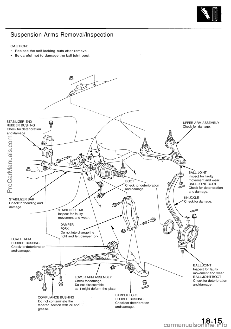
Suspension Arms Removal/Inspection
CAUTION:
• Replace the self-locking nuts after removal.
• Be careful not to damage the ball joint boot.
STABILIZER END
RUBBER BUSHING
Check for deterioration
and damage.
UPPER ARM ASSEMBLY
Check for damage.
STABILIZER BAR
Check for bending and
damage.
BALL JOINT
Inspect for faulty
movement and wear.
BALL JOINT BOOT
Check for deterioration
and damage.
KNUCKLE
Check for damage.
LOWER ARM
RUBBER BUSHING
Check for deterioration
and damage.
BALL JOINT
Inspect for faulty
movement and wear.
BALL JOINT BOOT
Check for deterioration
and damage.
COMPLIANCE BUSHING
Do not contaminate the
tapered section with oil and
grease.
DAMPER FORK
RUBBER BUSHING
Check for deterioration
and damage.
LOWER ARM ASSEMBLY
Check for damage.
Do not disassemble
as it might deform the plate.
DAMPER
FORK
Do not interchange the
right and left damper fork.
STABILIZER LINK
Inspect for faulty
movement and wear.
BOOT
Check tor deterioration
and damage.ProCarManuals.com
Page 1043 of 1954
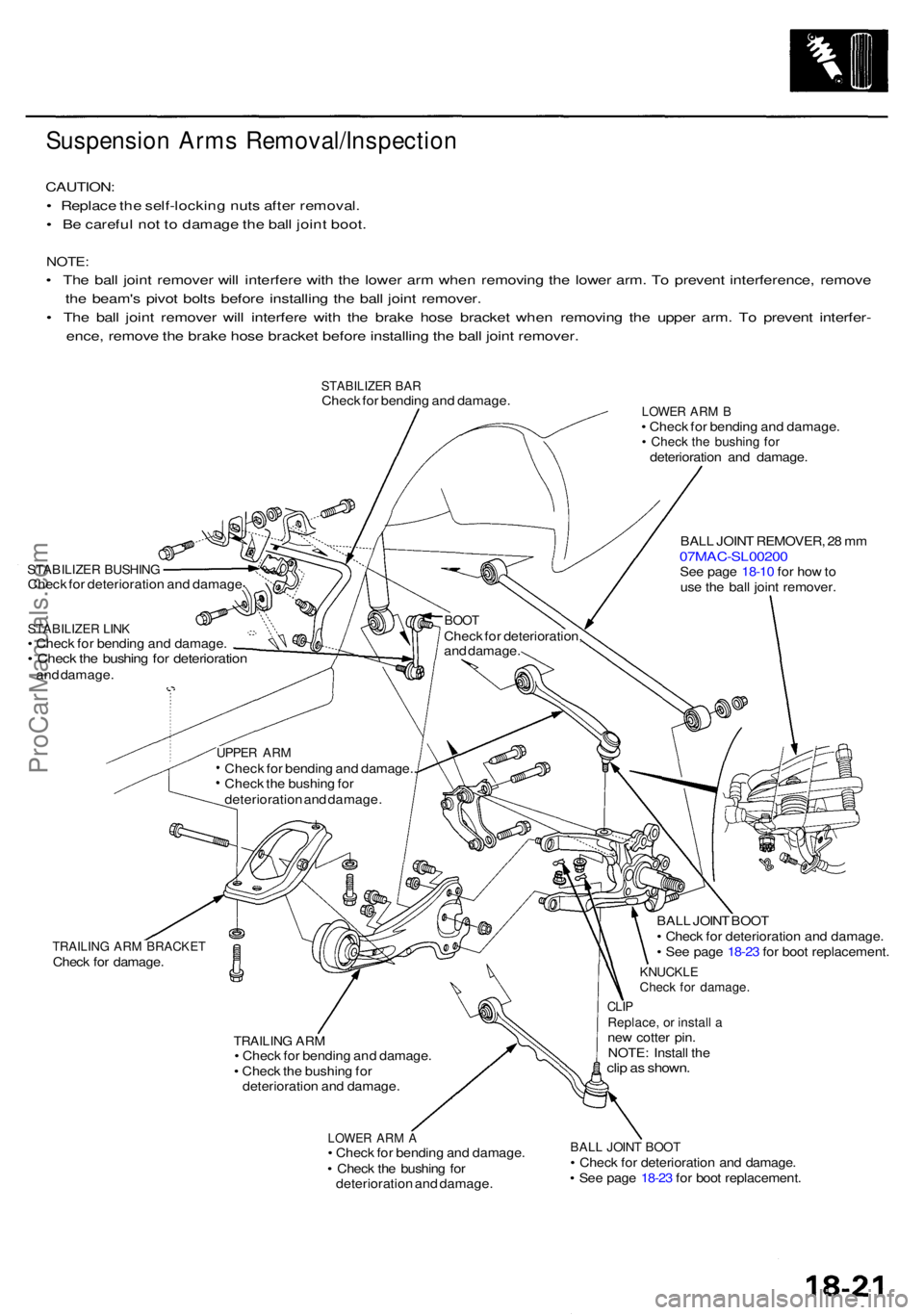
Suspension Arm s Removal/Inspectio n
CAUTION:
• Replac e th e self-lockin g nut s afte r removal .
• B e carefu l no t t o damag e th e bal l join t boot .
NOTE :
• Th e bal l join t remove r wil l interfer e wit h th e lowe r ar m whe n removin g th e lowe r arm . T o preven t interference , remov e
th e beam' s pivo t bolt s befor e installin g th e bal l join t remover .
• Th e bal l join t remove r wil l interfer e wit h th e brak e hos e bracke t whe n removin g th e uppe r arm . T o preven t interfer -
ence , remov e th e brak e hos e bracke t befor e installin g th e bal l join t remover .
STABILIZE R BA RChec k fo r bendin g an d damage .
STABILIZE R BUSHIN GCheck fo r deterioratio n an d damag e
STABILIZE R LIN K• Chec k fo r bendin g an d damage .• Chec k th e bushin g fo r deterioratio nand damage .
LOWER AR M B• Chec k fo r bendin g an d damage .• Chec k th e bushin g fo rdeterioratio n an d damage .
BAL L JOIN T REMOVER , 2 8 m m
07MAC-SL0020 0See pag e 18-1 0 fo r ho w to
us e th e bal l join t remover .
TRAILING AR M BRACKE TCheck fo r damage .
TRAILING AR M• Chec k fo r bendin g an d damage .
• Chec k th e bushin g fo r
deterioratio n an d damage .
LOWER AR M A• Chec k fo r bendin g an d damage .
• Chec k th e bushin g fo r
deterioratio n an d damage . BAL
L JOIN T BOO T
• Chec k fo r deterioratio n an d damage .
• Se e pag e 18-2 3 fo r boo t replacement .
KNUCKLECheck fo r damage .
CLIPReplace , o r instal l ane w cotte r pin .
NOTE : Instal l th e
clip a s shown .
BALL JOIN T BOO T• Chec k fo r deterioratio n an d damage .
• Se e pag e 18-2 3 fo r boo t replacement .
BOOTChec k fo r deterioration ,
an d damage .
UPPER AR MChec k fo r bendin g an d damage. .
Chec k th e bushin g fo r
deterioratio n an d damage .
ProCarManuals.com
Page 1045 of 1954
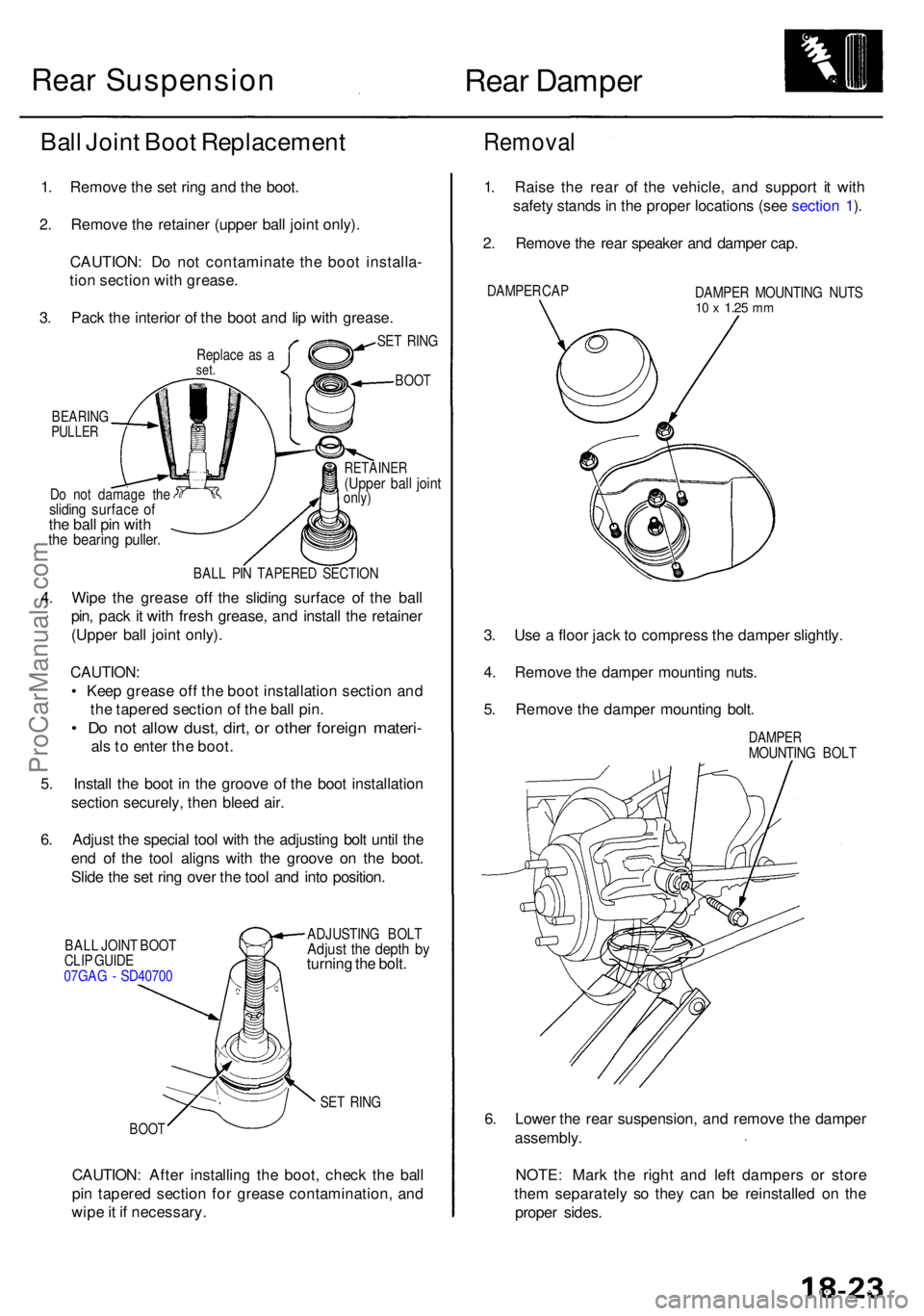
Rear Dampe r
Do no t damag e th eslidin g surfac e o fthe bal l pi n wit hthe bearin g puller .
RETAINE R(Upper bal l join tonly)
BAL L PI N TAPERE D SECTIO N
4. Wip e th e greas e of f th e slidin g surfac e o f th e bal l
pin , pac k i t wit h fres h grease , an d instal l th e retaine r
(Uppe r bal l join t only) .
CAUTION :
• Kee p greas e of f th e boo t installatio n sectio n an d
th e tapere d sectio n o f th e bal l pin .
• D o no t allo w dust , dirt , o r othe r foreig n materi -
als to ente r th e boot .
5 . Instal l th e boo t i n th e groov e o f th e boo t installatio n
sectio n securely , the n blee d air .
6 . Adjus t th e specia l too l wit h th e adjustin g bol t unti l th e
en d o f th e too l align s wit h th e groov e o n th e boot .
Slid e th e se t rin g ove r th e too l an d int o position .
BALL JOIN T BOO T
CLI P GUID E
07GA G - SD4070 0 ADJUSTIN
G BOL TAdjust th e dept h b yturnin g th e bolt .
SET RIN G
BOO T
CAUTION : Afte r installin g th e boot , chec k th e bal l
pi n tapere d sectio n fo r greas e contamination , an d
wip e it i f necessary .
Removal
1. Rais e th e rea r o f th e vehicle , an d suppor t i t wit h
safet y stand s in th e prope r location s (se e sectio n 1 ).
2 . Remov e th e rea r speake r an d dampe r cap .
DAMPE R CA P
DAMPER MOUNTIN G NUT S10 x 1.2 5 mm
3. Us e a floo r jac k t o compres s th e dampe r slightly .
4 . Remov e th e dampe r mountin g nuts .
5 . Remov e th e dampe r mountin g bolt .
DAMPE RMOUNTIN G BOL T
6. Lowe r th e rea r suspension , an d remov e th e dampe r
assembly .
NOTE : Mar k th e righ t an d lef t damper s o r stor e
the m separatel y s o the y can be reinstalle d o n th e
prope r sides .
SET RIN G
BOO T
Ball Join t Boo t Replacemen t
1. Remov e th e se t rin g an d th e boot .
2 . Remov e th e retaine r (uppe r bal l join t only) .
CAUTION : D o no t contaminat e th e boo t installa -
tio n sectio n wit h grease .
3 . Pac k th e interio r o f th e boo t an d li p wit h grease .
Replace a s aset .
BEARIN GPULLER
Rear Suspension
ProCarManuals.com
Page 1050 of 1954
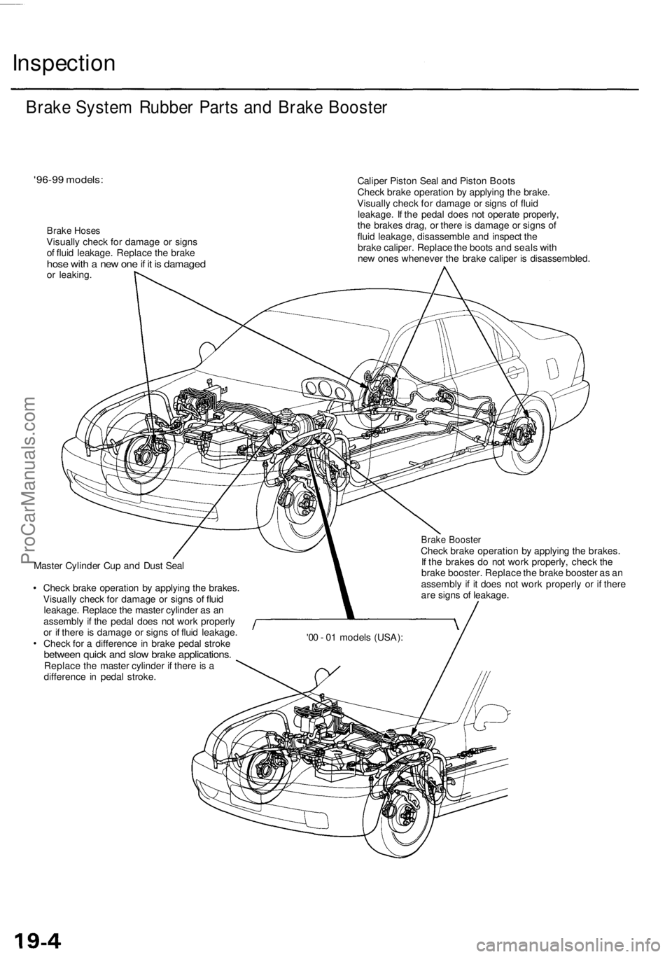
Inspection
'96-99 models:
Brake Hoses
Visually check for damage or signs
of fluid leakage. Replace the brake
hose with a new one if it is damaged
or leaking.
Caliper Piston Seal and Piston Boots
Check brake operation by applying the brake.
Visually check for damage or signs of fluid
leakage. If the pedal does not operate properly,
the brakes drag, or there is damage or signs of
fluid leakage, disassemble and inspect the
brake caliper. Replace the boots and seals with
new ones whenever the brake caliper is disassembled.
Master Cylinder Cup and Dust Seal
Check brake operation by applying the brakes.
Visually check for damage or signs of fluid
leakage. Replace the master cylinder as an
assembly if the pedal does not work properly
or if there is damage or signs of fluid leakage.
Check for a difference in brake pedal stroke
between quick and slow brake applications.
Replace the master cylinder if there is a
difference in pedal stroke.
Brake Booster
Check brake operation by applying the brakes.
If the brakes do not work properly, check the
brake booster. Replace the brake booster as an
assembly if it does not work properly or if there
are signs of leakage.
Brake System Rubber Parts and Brake Booster
'00 - 01 models (USA):ProCarManuals.com
Page 1056 of 1954
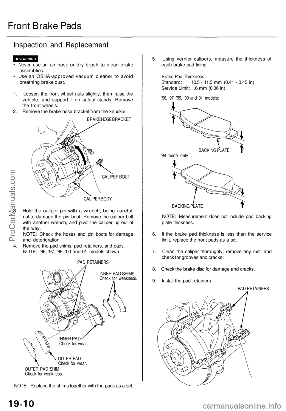
Front Brak e Pad s
Inspectio n an d Replacemen t
• Neve r us e a n ai r hos e o r dr y brus h t o clea n brake
assemblies .
• Us e a n OSHA-approve d vacuu m cleane r t o avoi d
breathin g brak e dust .
1 . Loose n th e fron t whee l nut s slightly , the n rais e th e
vehicle , an d suppor t i t o n safet y stands . Remov e
th e fron t wheels .
2 . Remov e th e brak e hos e bracke t fro m th e knuckle .
BRAKE HOS E BRACKE T
CALIPE R BOL T
CALIPE R BOD Y
3. Hol d th e calipe r pi n wit h a wrench , bein g carefu l
not t o damag e th e pi n boot . Remov e th e calipe r bol t
wit h anothe r wrench , an d pivo t th e calipe r u p ou t o f
the way .
NOTE : Chec k th e hose s an d pi n boot s fo r damag e
an d deterioration .
4 . Remov e th e pa d shims , pa d retainers , an d pads .
NOTE : '96 , '97 , '99 , '0 0 an d 0 1 model s shown .
PAD RETAINER S
INNER PA D SHIM SCheck fo r weakness .
OUTE R PA D
Chec k fo r wear .
OUTE R PA D SHI M
Chec k fo r weakness .
NOTE: Replac e th e shim s togethe r wit h th e pad s a s a set . 5
. Usin g vernie r calipers , measur e th e thicknes s of
eac h brak e pa d lining .
Brake Pa d Thickness :
Standard: 10. 5 - 11. 5 m m (0.4 1 - 0.4 5 in )
Servic e Limit : 1. 6 m m (0.0 6 in )
'96 , '97 , '99 , '0 0 an d 0 1 models :
BACKIN G PLAT E
NOTE: Measuremen t doe s no t includ e pa d backin g
plat e thickness .
6 . I f th e brak e pa d thicknes s i s les s tha n th e servic e
limit , replac e th e fron t pad s a s a set .
7 . Clea n th e calipe r thoroughly ; remov e an y rust , an d
chec k fo r groove s an d cracks .
8 . Chec k th e brak e dis c fo r damag e an d cracks .
9 . Instal l th e pa d retainers .
PAD RETAINER S
BACKIN
G PLAT E
'9 8 mode l onl y
INNE R PA DChec k fo r wear .
ProCarManuals.com
Page 1057 of 1954
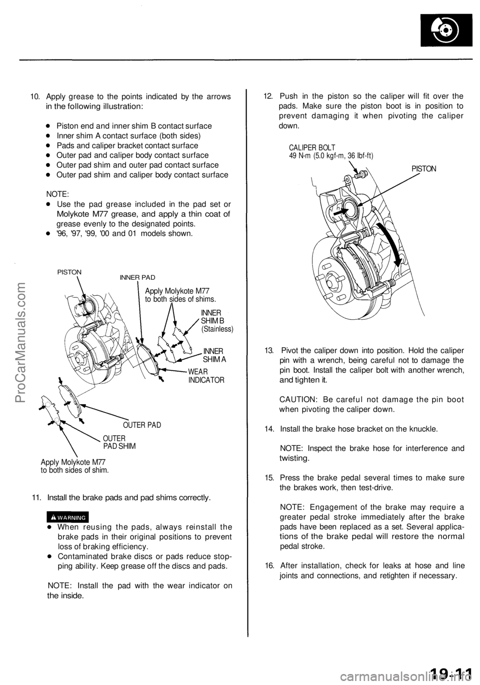
10. Apply grease to the points indicated by the arrows
in the following illustration:
Piston end and inner shim B contact surface
Inner shim A contact surface (both sides)
Pads and caliper bracket contact surface
Outer pad and caliper body contact surface
Outer pad shim and outer pad contact surface
Outer pad shim and caliper body contact surface
NOTE:
Use the pad grease included in the pad set or
Molykote M77 grease, and apply a thin coat of
grease evenly to the designated points.
'96, '97, '99, '00 and 01 models shown.
PISTON
INNER PAD
Apply Molykote M77
to both sides of shims.
INNER
SHIM B
(Stainless)
INNER
SHIM A
WEAR
INDICATOR
OUTER PAD
OUTER
PAD
SHIM
Apply Molykote M77
to both sides of shim.
11. Install the brake pads and pad shims correctly.
When reusing the pads, always reinstall the
brake pads in their original positions to prevent
loss of braking efficiency.
Contaminated brake discs or pads reduce stop-
ping ability. Keep grease off the discs and pads.
NOTE: Install the pad with the wear indicator on
the inside.
12. Push in the piston so the caliper will fit over the
pads. Make sure the piston boot is in position to
prevent damaging it when pivoting the caliper
down.
CALIPER BOLT
49 N-m (5.0 kgf-m, 36 Ibf-ft)
PISTON
13. Pivot the caliper down into position. Hold the caliper
pin with a wrench, being careful not to damage the
pin boot. Install the caliper bolt with another wrench,
and tighten it.
CAUTION: Be careful not damage the pin boot
when pivoting the caliper down.
14. Install the brake hose bracket on the knuckle.
NOTE: Inspect the brake hose for interference and
twisting.
15. Press the brake pedal several times to make sure
the brakes work, then test-drive.
NOTE: Engagement of the brake may require a
greater pedal stroke immediately after the brake
pads have been replaced as a set. Several applica-
tions of the brake pedal will restore the normal
pedal stroke.
16. After installation, check for leaks at hose and line
joints and connections, and retighten if necessary.ProCarManuals.com
Page 1059 of 1954
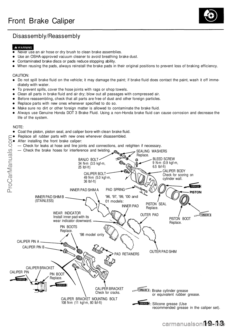
Front Brake Caliper
Disassembly/Reassembly
Never use an air hose or dry brush to clean brake assemblies.
Use an OSHA-approved vacuum cleaner to avoid breathing brake dust.
Contaminated brake discs or pads reduce stopping ability.
When reusing the pads, always reinstall the brake pads in their original positions to prevent loss of braking efficiency.
CAUTION:
Do not spill brake fluid on the vehicle; it may damage the paint; if brake fluid does contact the paint, wash it off imme-
diately with water.
To prevent spills, cover the hose joints with rags or shop towels.
Clean all parts in brake fluid and air dry; blow out all passages with compressed air.
Before reassembling, check that all parts are free of dust and other foreign particles.
Replace parts with new ones whenever specified to do so.
Make sure no dirt or other foreign matter is allowed to contaminate the brake fluid.
Always use Genuine Honda DOT 3 Brake Fluid. Using a non-Honda brake fluid can cause corrosion and decrease the
life of the system.
INNER PAD SHIM A
INNER PAD SHIM B
(STAINLESS)
'96, '97, '99,
'00 and
01 models:
INNER PAD
WEAR INDICATOR
Install inner pad with its
wear indicator downward.
PISTON SEAL
Replace.
OUTER PAD
PIN BOOTS
Replace.
'98 model only
CALIPER PIN A
CALIPER PIN B
CALIPER BRACKET
CALIPER PIN
PIN BOOT
Replace.
PISTON BOOT
Replace.
PAD RETAINERS
OUTER PAD SHIM
CALIPER BRACKET
Check for cracks.
CALIPER BRACKET MOUNTING BOLT
108 N-m (11 kgf-m, 80 Ibf-ft)
Brake cylinder grease
or equivalent rubber grease.
Silicone grease (Use
recommended grease in the caliper set).
NOTE:
Coat the piston, piston seal, and caliper bore with clean brake fluid.
Replace all rubber parts with new ones whenever disassembled.
After installing the front brake caliper:
— Check for leaks at hose and line joints and connections, and retighten if necessary.
— Check the brake hoses for interference and twisting.
BANJO BOLT
34 N-m (3.5 kgf-m,
25 Ibf-ft)
CALIPER BOLT
49 N-m (5.0 kgf-m,
36 Ibf-ft)
SEALING WASHERS
Replace.
BLEED SCREW
9 N-m (0.9 kgf-m,
6.5 Ibf-ft)
CALIPER BODY
Check for scoring on
cylinder wall.
PAD SPRINGProCarManuals.com
Page 1065 of 1954
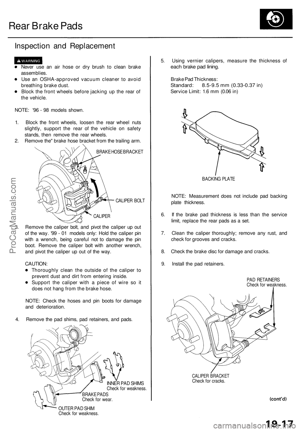
Rear Brake Pads
Inspection and Replacement
Never use an air hose or dry brush to clean brake
assemblies.
Use an OSHA-approved vacuum cleaner to avoid
breathing brake dust.
Block the front wheels before jacking up the rear of
the vehicle.
NOTE: '96 - 98 models shown.
1. Block the front wheels, loosen the rear wheel nuts
slightly, support the rear of the vehicle on safety
stands, then remove the rear wheels.
2. Remove the" brake hose bracket from the trailing arm.
BRAKE HOSE BRACKET
CALIPER BOLT
3.
CALIPER
Remove the caliper bolt, and pivot the caliper up out
of the way. '99 - 01 models only: Hold the caliper pin
with a wrench, being careful not to damage the pin
boot. Remove the caliper bolt with another wrench,
and pivot the caliper up out of the way.
CAUTION:
Thoroughly clean the outside of the caliper to
prevent dust and dirt from entering inside.
Support the caliper with a piece of wire so it
does not hang from the brake hose.
NOTE: Check the hoses and pin boots for damage
and deterioration.
4. Remove the pad shims, pad retainers, and pads.
INNER PAD SHIMS
Check for weakness.
BRAKE PADS
Check for wear.
OUTER PAD SHIM
Check for weakness.
5. Using vernier calipers, measure the thickness of
each brake pad lining.
Brake Pad Thickness:
Standard: 8.5-9.5 mm (0.33-0.37 in)
Service Limit: 1.6 mm (0.06 in)
BACKING PLATE
NOTE: Measurement does not include pad backing
plate thickness.
6. If the brake pad thickness is less than the service
limit, replace the rear pads as a set.
7. Clean the caliper thoroughly; remove any rust, and
check for grooves and cracks.
8. Check the brake disc for damage and cracks.
9. Install the pad retainers.
PAD RETAINERS
Check for weakness.
CALIPER BRACKET
Check for cracks.ProCarManuals.com